Model: K-3864
2 ¼" Load Alarm Kit
06/2004 −Rev. OR
TABLE OF CONTENTS PAGE
1.0
Product Information............................................................................................................................................................1
2.0
Safety Information..............................................................................................................................................................1
2.1
Alarm And Warning Systems..................................................................................................................................1
2.2
Warning And Danger Signs ....................................................................................................................................1
2.3
Component Safety Features...................................................................................................................................1
2.4
Functional Safety Features.....................................................................................................................................1
2.5
Features For Operator Safety.................................................................................................................................1
2.6
Environmental Safety Features...............................................................................................................................1
2.7
Protection Systems.................................................................................................................................................1
2.8
Closed Circuits........................................................................................................................................................1
2.9
Interlocking .............................................................................................................................................................1
2.10
Necessary Personal Protective Equipment.............................................................................................................1
2.11
Safety Guidelines....................................................................................................................................................1
2.12
Conditions For Safe Use.........................................................................................................................................2
2.13
Operator Qualifications...........................................................................................................................................2
2.14
Additional Safety Measures....................................................................................................................................2
3.0
Packaging And Storage......................................................................................................................................................2
3.1
Packaging Requirements........................................................................................................................................2
3.2
Handling..................................................................................................................................................................2
3.3
Strapping ................................................................................................................................................................2
3.4
Packaging Protection..............................................................................................................................................2
3.5
Labeling Of Packaging............................................................................................................................................2
3.6
Storage Compatibility..............................................................................................................................................2
3.7
Storage Environment..............................................................................................................................................2
3.8
Storage Space And Handling Facilities:..................................................................................................................2
4.0
Transporting Requirements................................................................................................................................................2
5.0
Assembly............................................................................................................................................................................3
5.1
General Instructions................................................................................................................................................3
5.2
Pre-Use Checks......................................................................................................................................................3
5.3
Personnel Requirements ........................................................................................................................................3
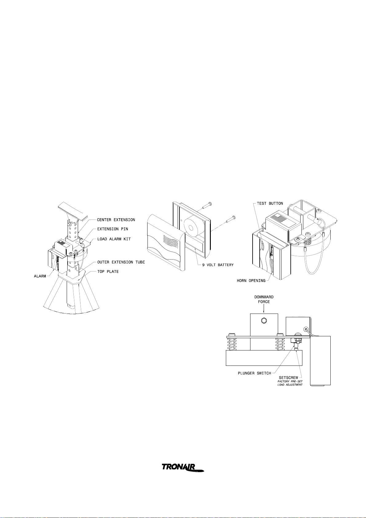
5.4
Assembly Steps......................................................................................................................................................3
5.5
Inspection And Test Procedures.............................................................................................................................3
6.0
Installation..........................................................................................................................................................................3
7.0
Operation ...........................................................................................................................................................................4
7.1
Operating Parameters.............................................................................................................................................4
7.2
Numerical Values....................................................................................................................................................4
7.3
Operator Controls ...................................................................................................................................................4
7.4
Operating Instructions.............................................................................................................................................4
7.4.1
Rules For Operating.................................................................................................................................4
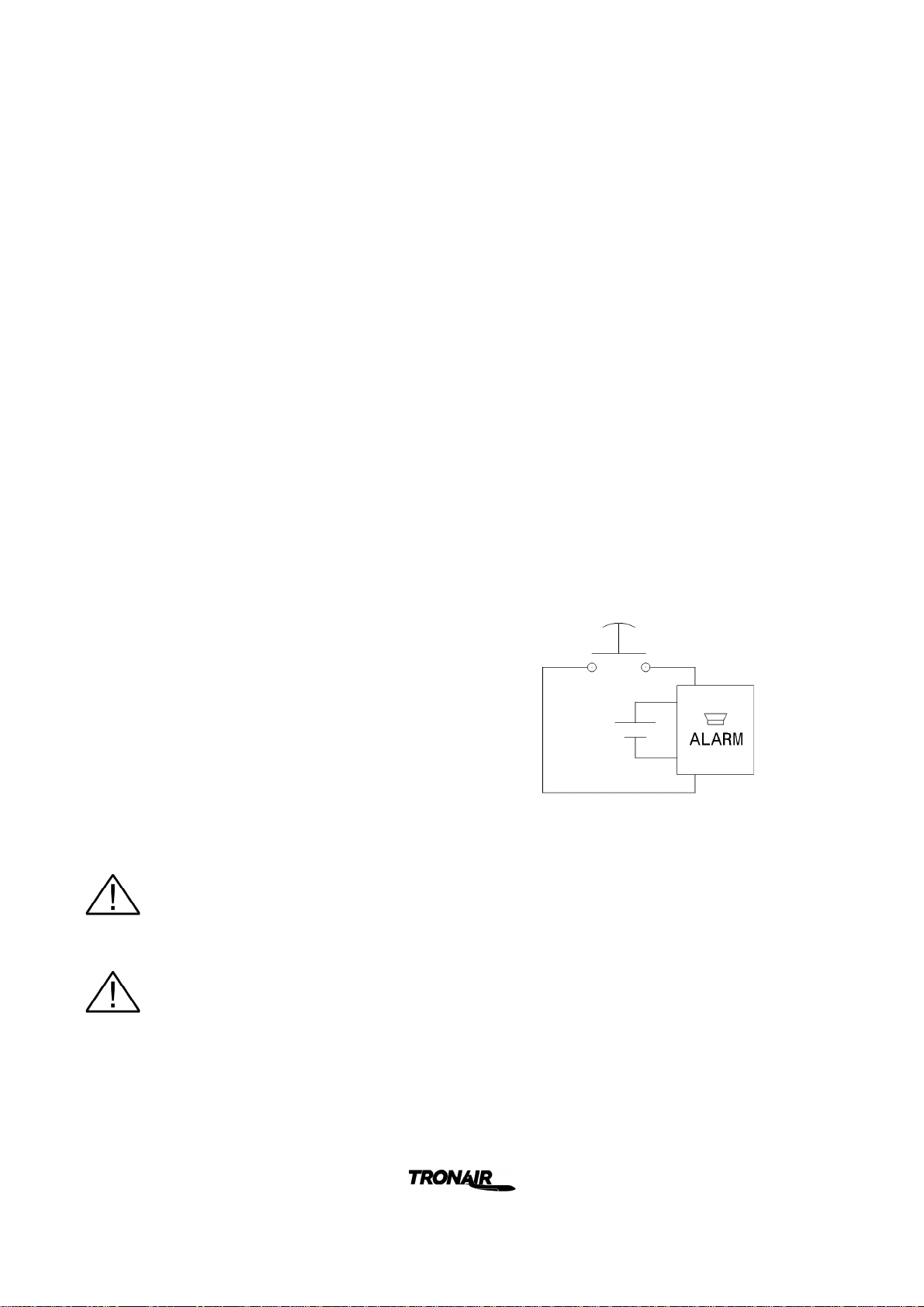
7.4.2
Alarm Operation And Test........................................................................................................................4
8.0
Training..............................................................................................................................................................................4
9.0
Maintenance.......................................................................................................................................................................5
General ..............................................................................................................................................................................5
9.1
Maintenance Schedule ...........................................................................................................................................5
9.2
Cleaning Alarm.......................................................................................................................................................5
10.0
Troubleshooting .................................................................................................................................................................5
11.0
Provision Of Spares ...........................................................................................................................................................5
11.1
Recommended Spares To Be Kept On Hand.........................................................................................................5
11.2
Parts List.................................................................................................................................................................5
12.0
In-Service Support..............................................................................................................................................................7
13.0
Guarantees/Limitation Of Liability ......................................................................................................................................7