Tronic TR10250 User manual

Residential ESS Battery Cabinet
TR10250 | TR20450 | TR30750| TR40950
Quick Guide
TRONIC ESS CO., LTD

1
Pr
o
duct Ov
e
rv
ie
w
1.1 ESS Battery Cabinet Product Appearance
ESS Battery Cabinet is applicable to the grid-tied or off-grid systems. It
can store and release electric energy based on service requirements.
Note: The TR20450 ( 10 kWh) model is used as an example.
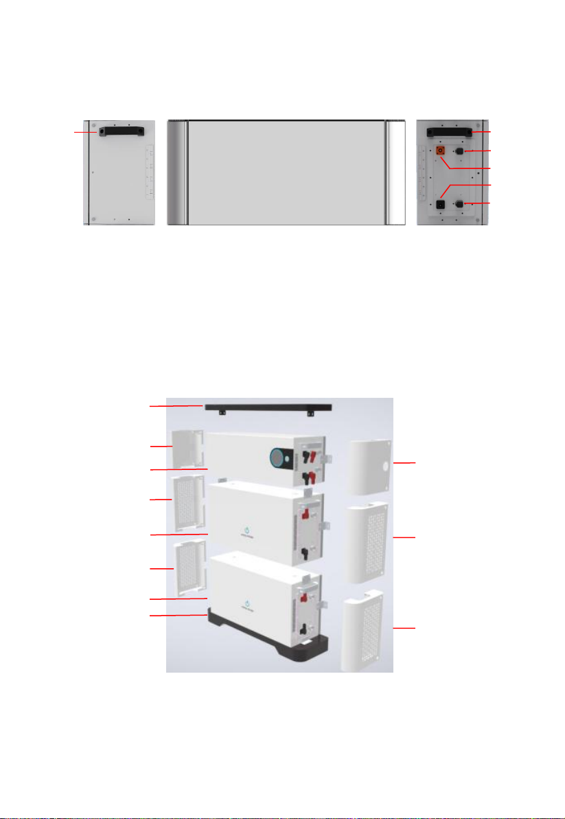
ESS Battery Cabinet consists of a power control module and battery expansion
modules. Each power control module is 5.12 kW, and can expanded to 4
power control modules. (total 20.48kWh).
Power control module
(1)Mounting handle (2)Disconnecting switch (3)Debugging port
(4)Power display (5)Start switch (6)Inverter COM port
(7) Inverter cascading terminals (8) Internal COM port
(9) Battery cascading terminals
Top Cover
Base
Battery expansion module
(5.12kWh)
Battery expansion module
(5.12kWh)
Power control module
DC Switch
Left View
9
2
Front View
Right View
8
7
6
5
4
1
3
1
Power control module
(1)Mounting handle (2)Internal COM port 1
(3)Battery cascading terminal(+) (4)Battery cascading terminal(-)
(5)Internal COM port 2
Product diagram
(1)Top cover (2)Protective cover (3)Power control module
(4)Battery expansion module (5)Bottom cover
1
2
3
2
4
2
4
5
2
2
2
Right View
Front View
2
3
4
1
5
1
Left View
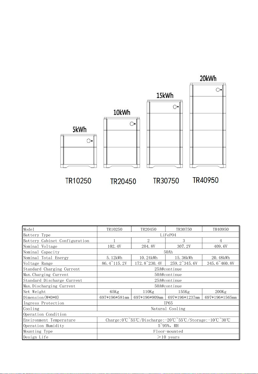
1.2 ESS Battery Cabinet Model
TRONIC ESS has different electricity products to meet user’s needs, such
as TR10250、TR20450、TR30750、TR40950.
1.3 Technical data
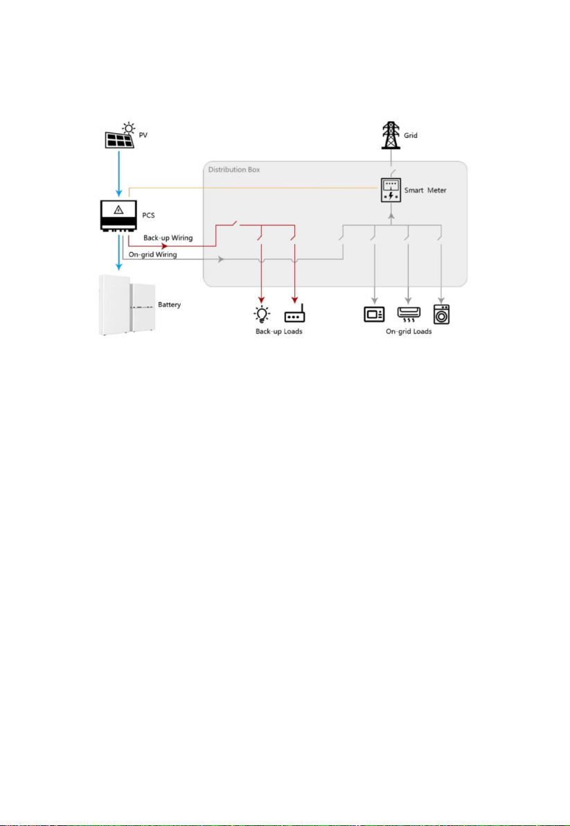
1.4 System Schematic

2
Device Installation
2.1 Installation Requirements
2.1.1 Installation Environment
2.1.2 Installation Space
inverter
front≥1000mm
unit:mm
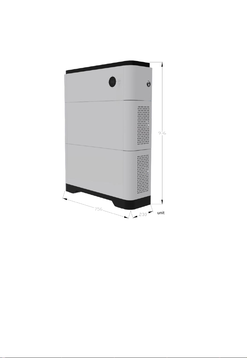
2.1.3 Mounting Hole Dimensions
unit:mm

2.2 Installation and fixation
1. Place the base in a horizontal position, then put the battery unit on the base.
(Note: pay attention to the red circle mark in the figure, the battery unit and the
base should be completely consistent to prevent dislocation).
2. Using a fixing piece to fix the battery unit with the base.
(Note: when fixing, the torque shall not exceed 1.2N. M to prevent equipment
damage.)
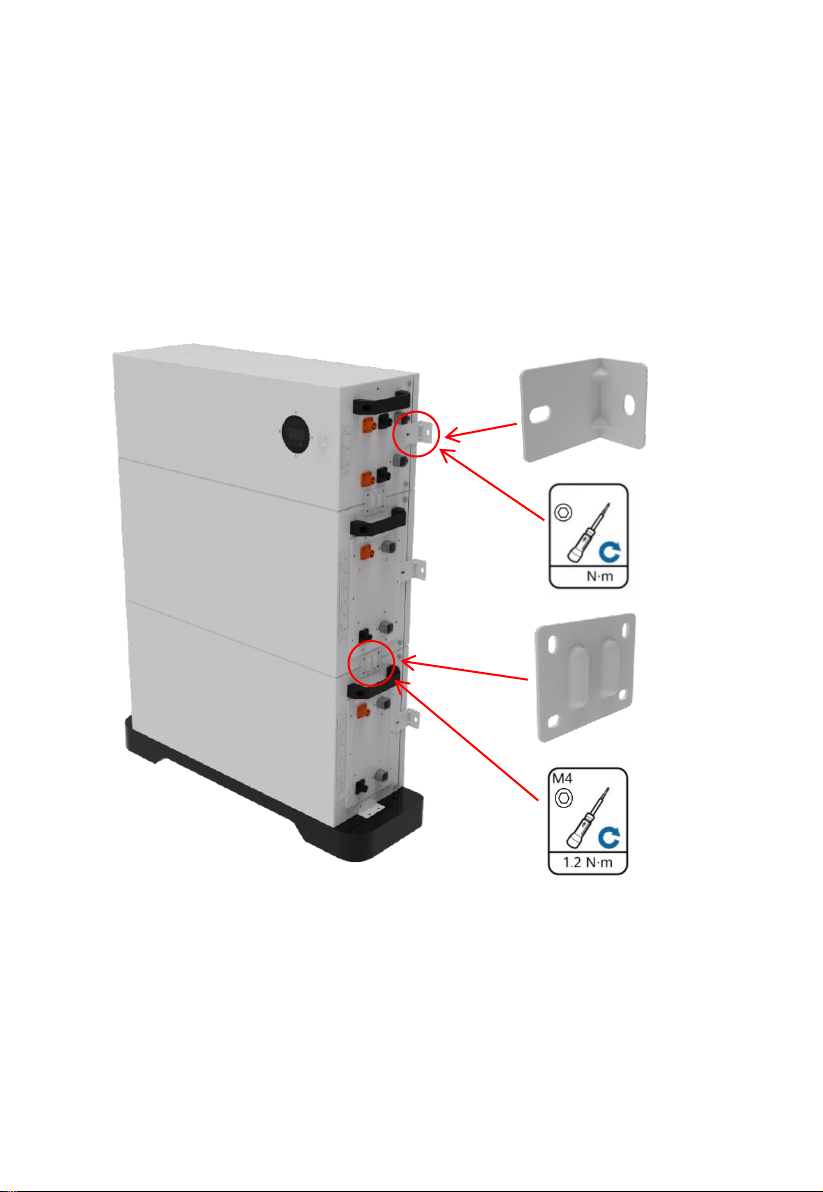
3. Place the remaining battery units and power control units respectively.
(Note: when fixing the component unit, the torque shall not exceed 1.2N. M
to prevent equipment damage. When fixing the wall, the torque shall not
exceed 1.2N. M; The power control unit is placed on the battery unit. The
legend is jk20450 product. There are two battery units, each 5kwh, the
battery unit parameters are the same, and the installation sequence is not
divided).
M6
5
3
Inte
rna
l
Electric
al
C
o
nn
ect
io
ns
o
f
the
Bat
t
e
ry
Note:
A. The internal connecting wires are packed in the box;
B. Before connecting cables, ensure that the switches of the devices are
turned off. Otherwise, high voltage electric shock and equipment
damage may be caused.
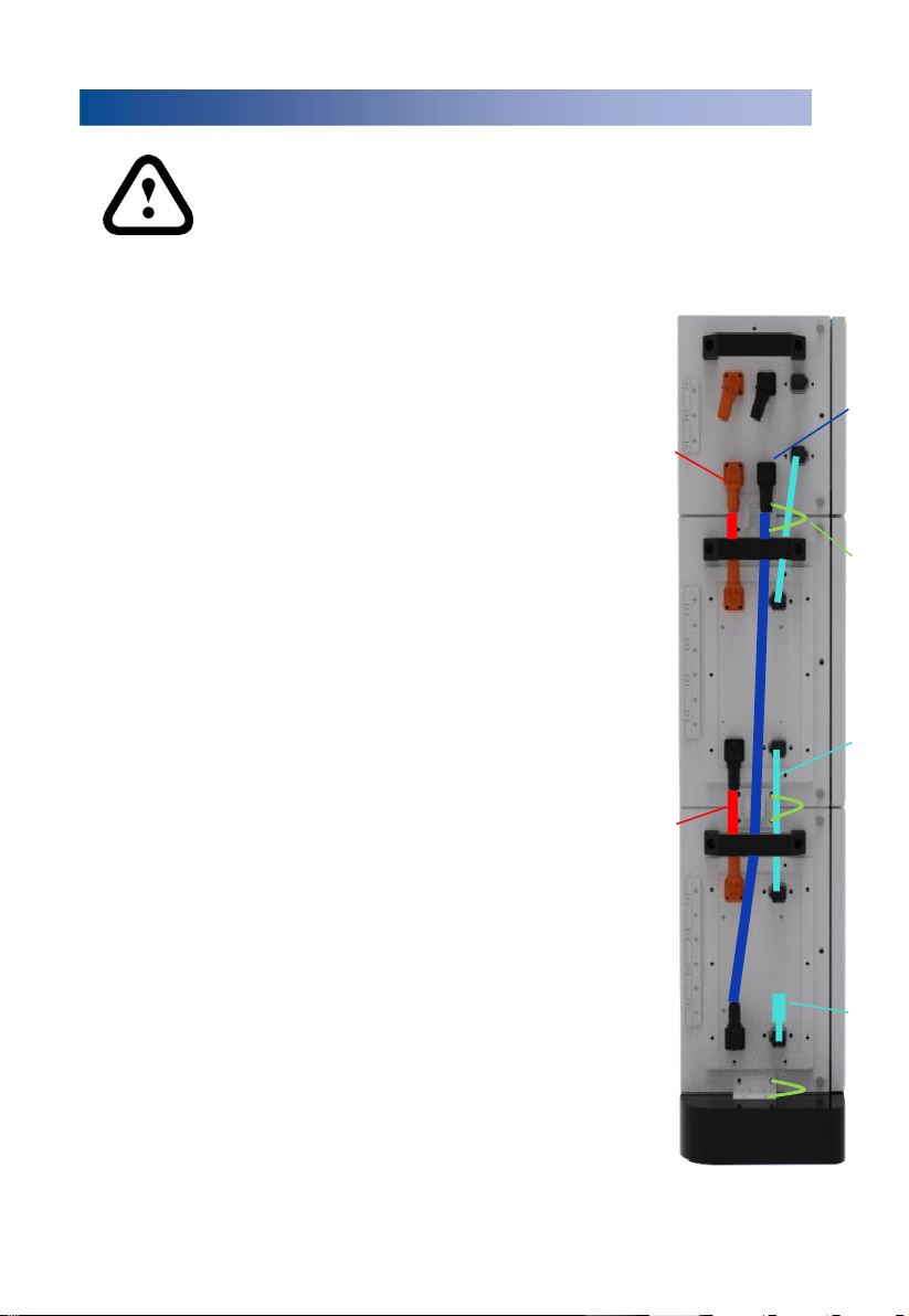
3.1 Connection of Battery Cable
The battery expansion modules in the ESS battery cabinet are
connected in series.
The top battery expansion module "+" is connected by
the power control module "battery cascading terminal
+", the top battery expansion module "-" is connected
to the next battery expansion module "+", and so on.
The lowest battery expansion module "-" is connected by the
"battery cascading terminal" of the power control module- .
3.2 Connection of Communication Cables
The ESS Battery Cabinet uses Daisy chain for internal
communication.
As shown in the figure, the battery expansion modules are
connected one by one.
The battery expansion module at the top is connected with the
power control module internal communication interface
the bottom battery expansion module’s internal COM port is
connected to a terminal resistance.
3.3 Connection of Internal Ground Cable
For the internal ground cable of the ESS Battery Cabinet,
connecting each component unit one by one as shown in right
picture.
-
+
-
+
Battery Cascading
Terminal -
Ground
Cable
Internal
Communication
Cable
Battery
cable
Battery Cascading
Terminal +
Terminal
Resistance

4
Ex
tern
al
Electric
al
C
o
nn
ect
io
ns
o
f
the
Bat
t
e
ry
Note:
A. The internal connecting wires are packed in the box;
B. Before connecting cables, ensure that the switches of the devices
are turned off. Otherwise, high voltage electric shock and equipment
damage may be caused.
4.1 cable specification
No.
Cable
Type
ConductorCross-
Sectional Area Range
1
Ground cable
Single-core outdoor
copper-core cable
4-6 mm2
2
DC input power cable
(inverter to battery
and battery to
Common outdoorPV
cable in the industry
10 mm2
3
Signal cable (inverter
to battery and
battery to battery)
Outdoor shielded
twisted pair cable (8
cores)
0.20–0.35 mm2
4.2 External Cable Connection
As shown in the following figure, external cables are routed through
cable holes on the side panel and connected to ports on the PDU side.
Inverter cascading terminal+
Inverter communication cable
Ground cable
Inverter cascading terminal-
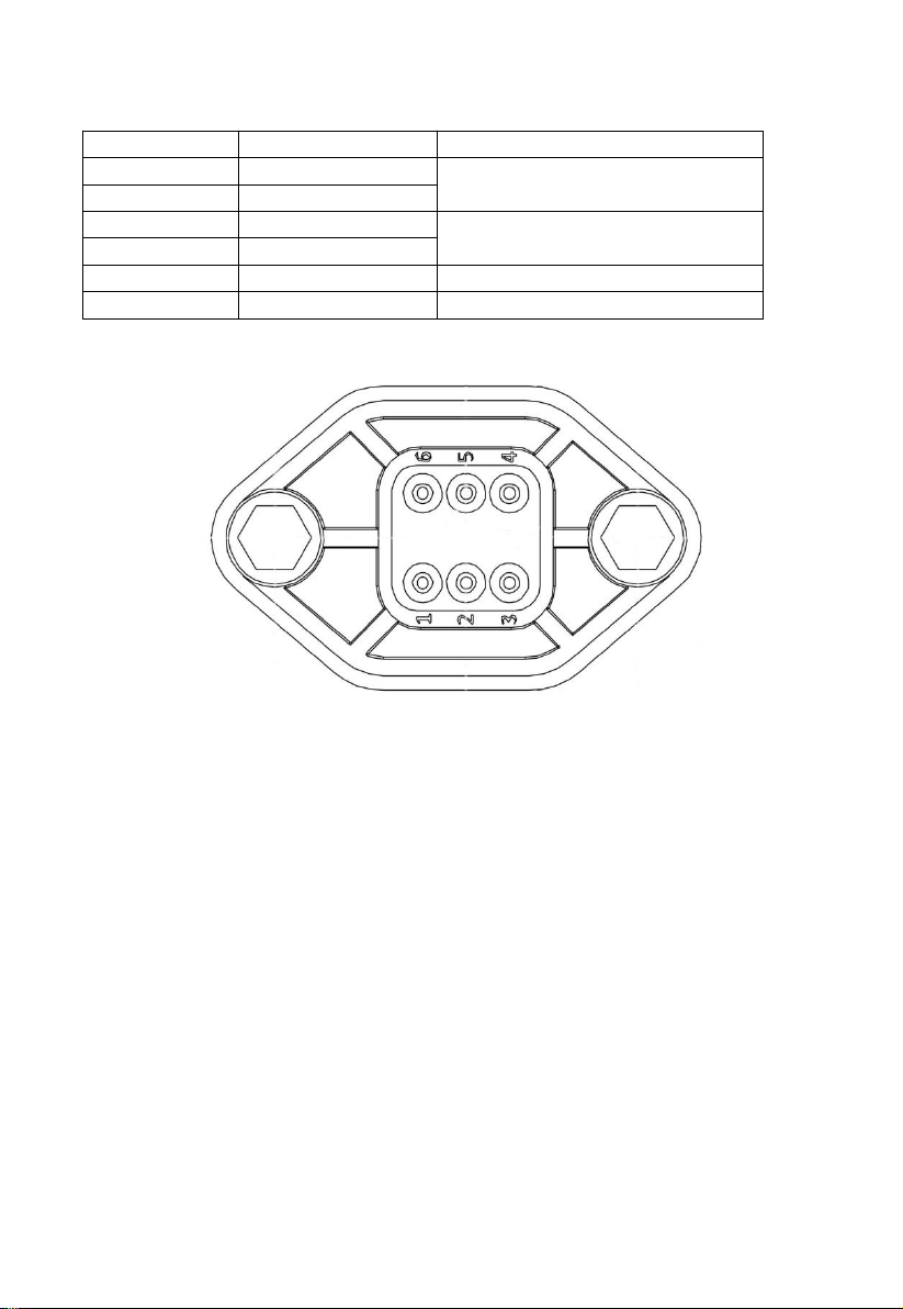
4.3 COM Port Pin Definitions
PIN
Definition
note
1
External CANH
Communicate with inverter CAN
2
External CANL
3
RS485-A
Communicate with inverter 485
4
RS485-B
5
NC
6
NC
5
Ve
rifying
the
Insta
lla
tion
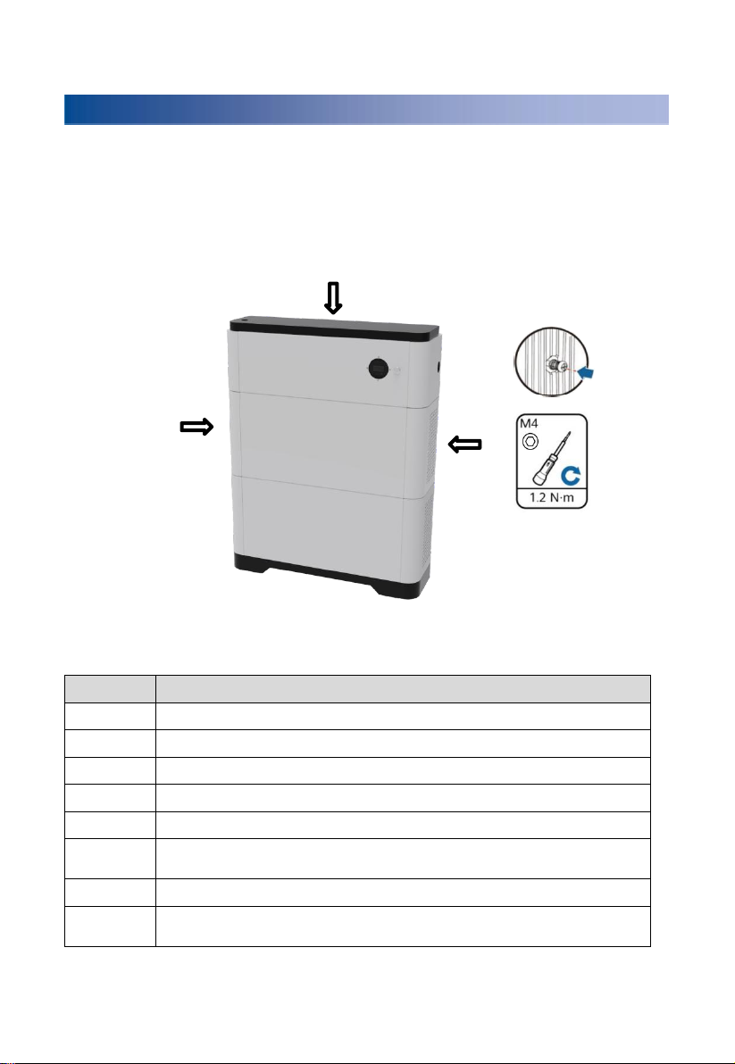
5.1 Installing Cover
After electrical connections are complete, check that cables are
correctly and securely connected, install the external protective cover, and
secure it using screws.
No.
AcceptanceCriterion
1
The battery is installed correctly and securely.
2
The cables are routed properly as required by the customer.
3
Cable ties are secured evenly and no burr exists.
4
The ground cable is connected correctly and securely.
5
The battery switch and all switches connected to the battery are OFF.
6
The DC input power cables and signal cables are connected correctly and
securely.
7
Idle terminals and ports are locked by watertight caps.
8
The installation space is proper, and the installation environment is clean
and tidy.

6 Power-On Commissioning
1. Confirm the connection between ESS battery cabinet and inverter before power on
for the first time starting. Turn the isolation switch of ESS battery cabinet and
inverter switch to "on"
(refer to inverter manual for specific inverter operation).
2. Press the start button. The equipment will be self-checked and started. If there is
no fault, the equipment can be used normally.
3. If the device is not used for a short time, press the start button and the device will
go to sleep mode. If the equipment is not used for a long time (two weeks), in
addition to the above steps, turn the equipment disconnector to "off".
OFF
ON
ALM
RUN

See the table below for status indication
System
state
Abnormal
event
RUN
ALM
SOC
Note
Off
/
Lights out
Lights out
Lights out
Standby
Normal
Light on
Lights out
Light on / display
percentage
according to
electric quantity
Alarm
Light on
Twinkle
Discharge
protection
Lights out
Light on
Lights out
Floating
charge
Normal
Light on
Lights out
Light on / display
percentage
according to
electric quantity
Alarm
Light on
Twinkle
Charging
protection
Twinkle
Light on
Charge
Normal
Twinkle
Lights out
Light on / display
percentage
according to
electric quantity
Alarm
Twinkle
Twinkle
Discharge
Normal
Light on
Lights out
Light on / display
percentage
according to
electric quantity
Alarm
Light on
Twinkle
RUN

7 Tool & safety gears required
1. Tools
The following tools are required to install the battery pack:
Precision screwdriver Drill Pencil or Marker
2. Safety gears for personal protection
It is recommended to wear the following safety gears when handling the
battery pack.
Insulated gloves Safety goggles Safety shoes

8 Inverter
Matched inverter brand and model
No.
Brand
Type
Note
1
GOODWE
GW3600-EH
2
GW5000-EH
3
GW6000-EH
4
GW5K-ET
5
GW8K-ET
6
GW10K-ET
7
SUNWAYS
STH-3KTL-HSS
8
STH-3.6KTL-HSS
9
STH-3KTL-HS
10
STH-3.6KTL-HS
11
STH-4.2KTL-HS
12
STH-4.6KTL-HS
13
STH-5KTL-HS
14
STH-6KTL-HS
15
STH-7KTL-HS
16
STH-8KTL-HS
17
KOYOE
KY-1Hybrid-5K0-H

9 Packing list
1.The outer packing box size of power control module is 820 * 400 * 495mm.
The details of accessories contained in the packing box are shown in the table below:
※ the number of power lines configured for Mint-JKE5, Mint-JKE10, Mint-
JKE15, and Mint-JKE20 is 0, 1, 2 and 3 respectively.
No.
Material name
Quantity
Note
1
Power control unit
1
2
Protective cover
1
left
3
Protective cover
1
right
4
cover
1
5
base
1
6
Power line
1
PDU“+”~PACK“+”
7
Power line
1
PDU“-”~PACK“-”
8
Power line
1/2/3
※ PACK “+”~PACK“-”
9
Power line
1
Connect inverter "+"
10
Power line
1
Connect inverter "-"
11
Communication line
1
Internal communication
12
Communication line
1
Inverter communication
13
RJ45 wiring converter
1
14
Screw M8*40L
4
15
Screw M4*12L
14
16
Screw M6*12L
4
17
Screw M5*10L
6
18
Base connecting piece
2
19
Wall connecting piece
2
20
Ground wire
1
21
Tie
5
22
user 's manua
1
23
Shipment report
1
24
certificate
1
25
Quality assurance card
1

2. The outer packing box size of battery expansion module is 760 * 425 * 420mm.
The details of accessories contained in the packing box are shown in the table below:
No.
Material name
Quantity
Note
1
Battery pack
1
2
Protective cover
1
left
3
Protective cover
1
right
4
Wire
1
COM port to COM port
5
Connecting piece
between boxes
2
6
Wall connecting piece
2
7
Screw M8*40L
4
8
Screw M4*12L
10
9
Screw M6*12L
4
10
Screw M5*10L
6
11
Ground wire
1
12
Tie
5
13
user 's manual
1
user 's manual
14
Shipment report
1
Shipment report
15
certificate
1
certificate
16
Quality assurance card
1
Quality assurance card

TRONIC ESS CO., LTD
Add: Room 401-1, Gaorong Building, High-speed Railway New Town,
Xiangcheng District, Suzhou City, Jiangsu Province, China
Web: http://www.tronic-te.com
Tel:+86-512-66101116
E-mail:jswzs@tronic-te.com
This manual suits for next models
3
Table of contents


