Trotec TTR 55 S User manual

TTR 55 S
Operating manual desiccant dehumidifier B - 1
T

A-1Operating manual – Dehumidifier TTR 55 S
B - 1
Table of contens
Unit description............................... B - 1
Installation...................................... B - 1
Safety information........................... B - 2
Commissioning ............................... B - 2
Decommissioning ........................... B - 4
Unit transport.................................. B - 4
Careandmaintenance.................... B - 5
Troubleshooting .............................. B - 5
Intended use................................... B - 6
Customerserviceandwarrantly...... B - 6
Protection and recycling.................. B - 6
Maintanancereport......................... B - 6
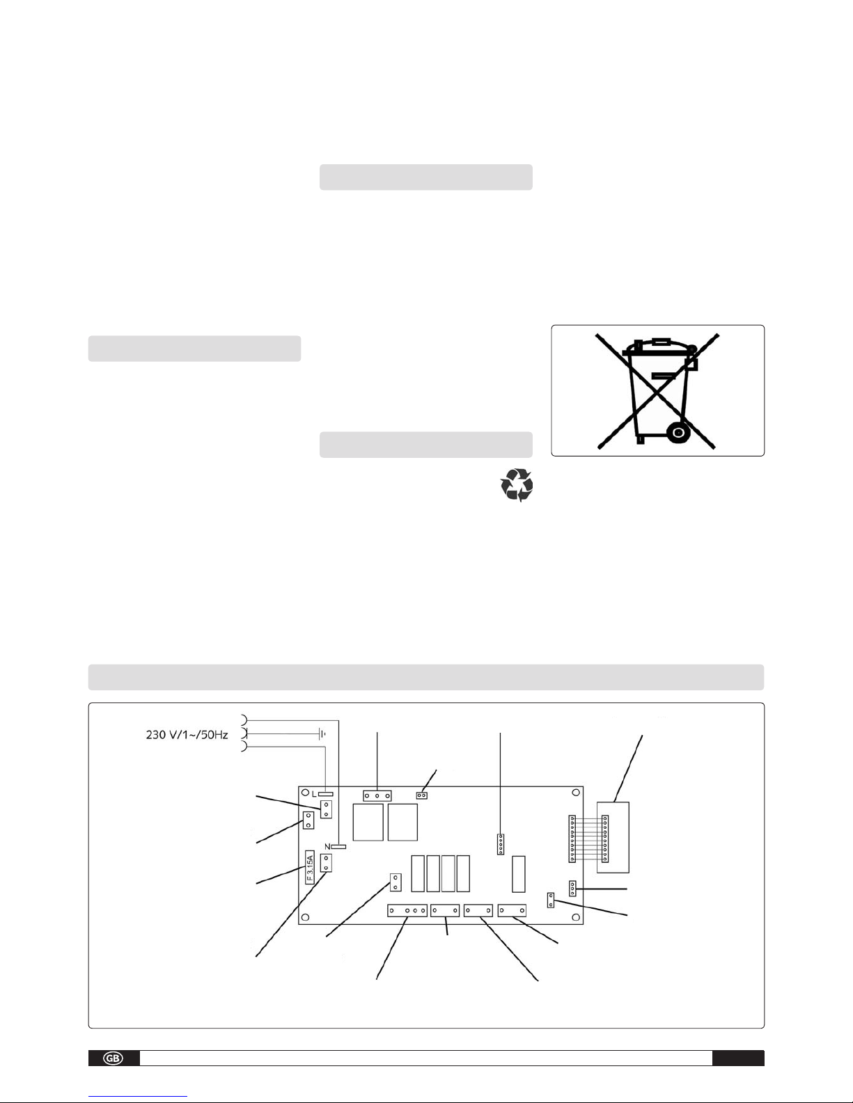
Electrical wiring diagramm.............. B - 7
Capacitygraph................................ B - 7
Technical data................................. B - 8
These operating instructions must be read ca-
refully before commissioning/using the unit!
These instructions are part of the unit and
musst always be kept near to the site of in-
stallation or unit.
The units are designed for universal and pro-
blem-free dehumidification.
Owing to their compact size, they are easy to
transport and install.
The units operate according to the adsorption
principle and are provided with ioniser, low noise
and maintenance recirculation fans as well as
power cord with plug.
The fully automatic control, the condensate con-
tainer with integrated overflow protection and the
drain connection for direct condensate discharge
ensure troublefree operation.
The units comply with the fundamental safety
and health requirements of the pertinent EU di-
rectives.
The units are reliable and easy to operate.
The units are used wherever dehumidification is
necessary and consequential damage (e.g. due
to mould formation) is to be avoided.
Unit description
The units are also suitable for drying and de-
humidification of:
• Living rooms, bedrooms, shower or cellar
rooms, lofts.
• Utilityrooms,weekendhomes,caravans.
• Museums,archives,laboratories.
• Wellness areas, washrooms and changing
rooms, etc..
• Garages, store rooms.
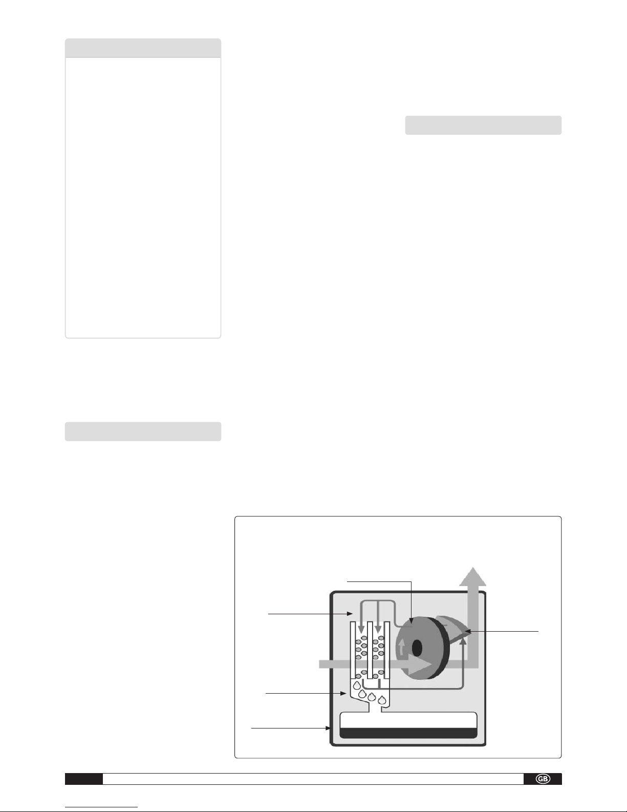
saturated air
condenser
humid room
air
regenerative
heatig element
adsorption rotor
dehumidified
room air
The air flow is cooled on its way through or via the condenser to below the dew point. The water
vapour condenses and is collectes in a condensate trap and discharged.
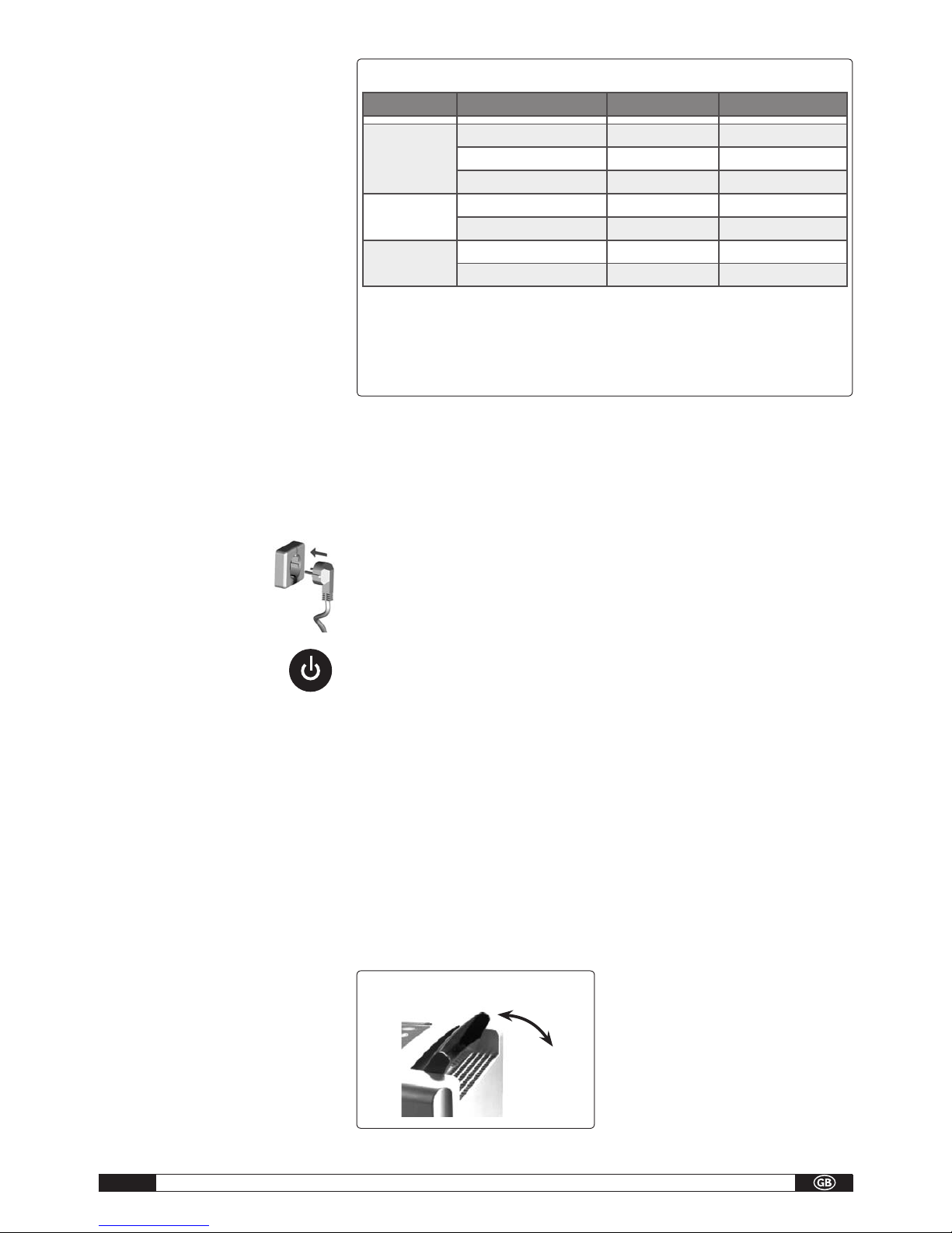
Operation
The units can be switched on and off with the ON/
OFF button. The LED of the last selected mode
lights up in the control panel. The recirculation
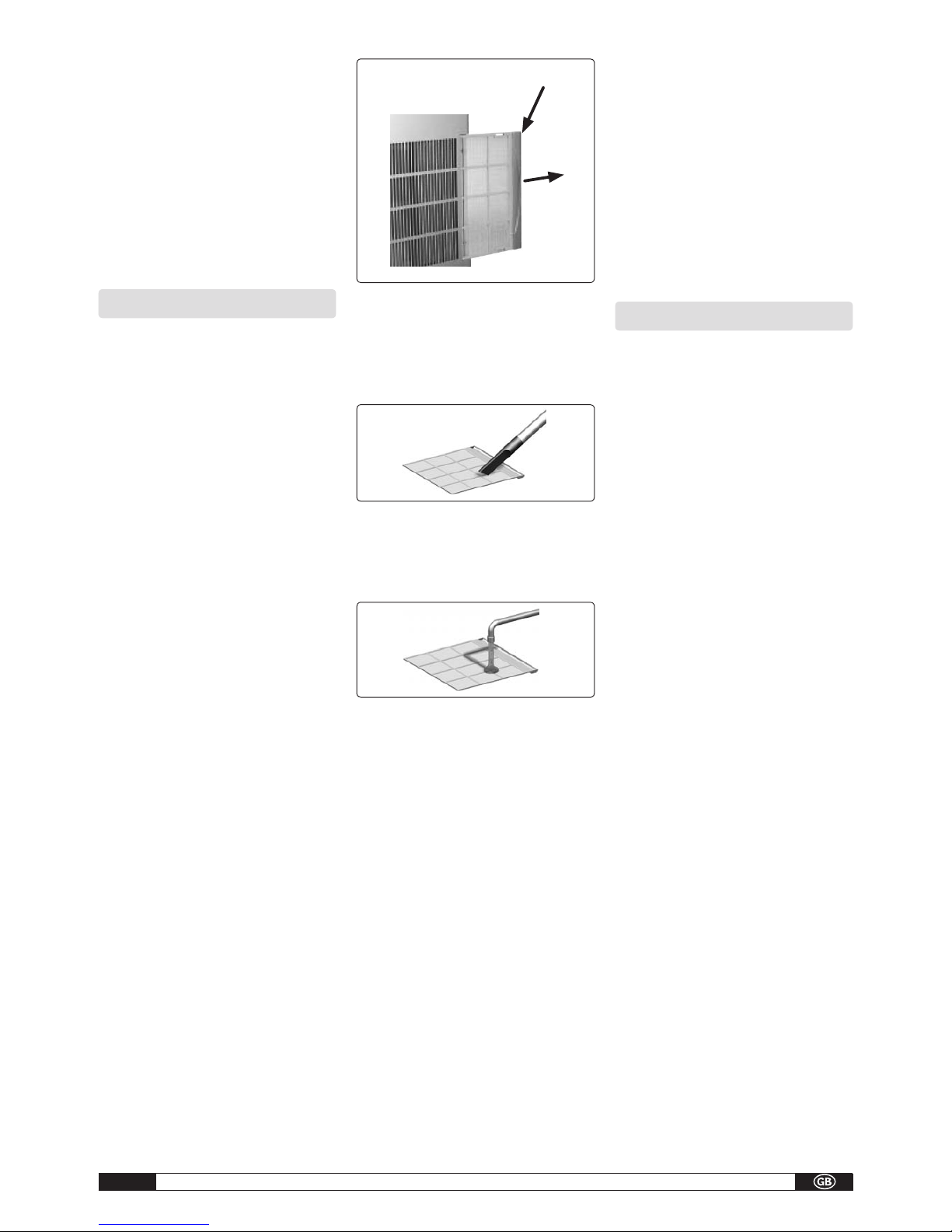
fan draws in the humid room air via the inlet gril-
le with filter, condenser and following adsorption
rotor.
In the internal regeneration circuit, the air flows
across a heating element, dries the adsorption-
rotor and passes the humid air through the con-
denser.
On the colder condenser, heat is removed from
the room air and cooled to below dew-point. The
water vapour contained in the room air deposits
as condensate.
Depending on the room air temperature and re-
lative humidity, the condensed water constantly
drips through the integrated drain connection into
the condensate container located below.
The conditioned drier air continuously mixes with
the room air. Due to the constant circulation of
the room air through the unit, the relative humidi-
ty in the room is gradually reduced to the requi-
red humidity (45% relative humidity).
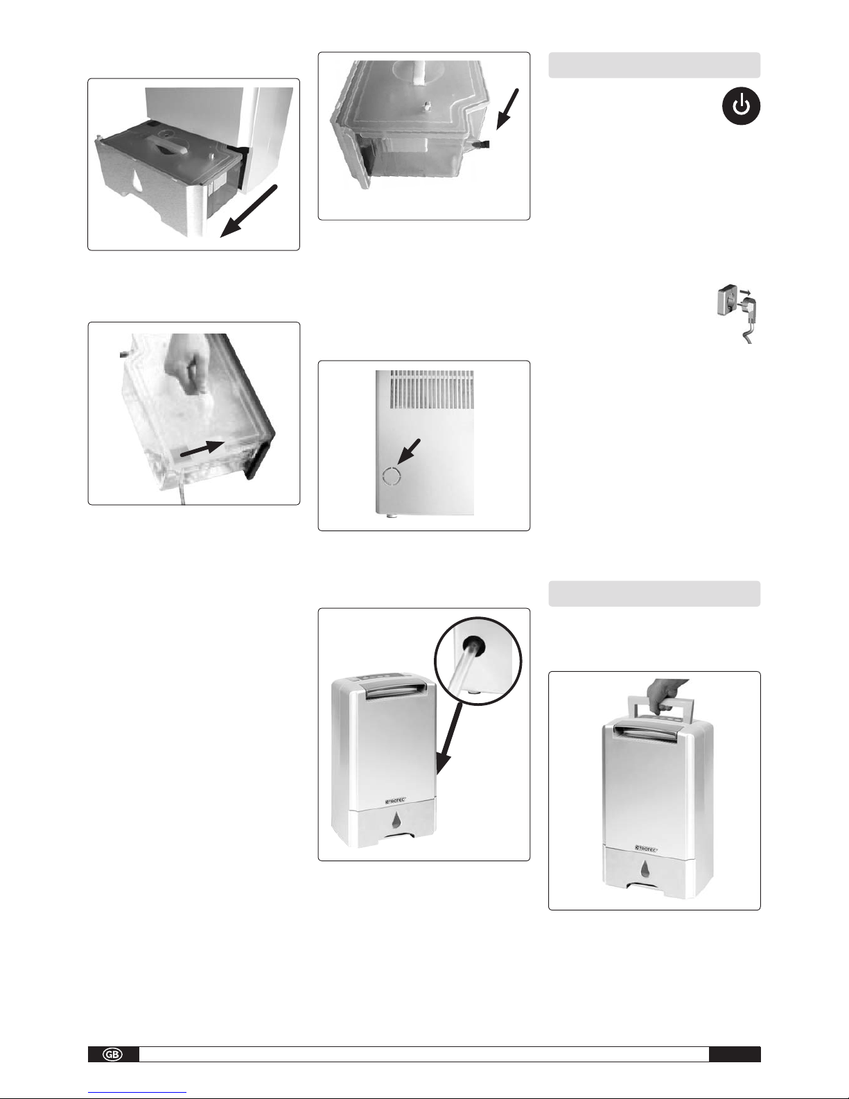
A float switch in the condensate container inter-
rupts dehumidification via a microswitch when
the container is full. The units switch off with an
audible signal (5x) and the „FULL TANK“ indicator
light illuminates on the control panel. This does
not extinguish until the emptied condensate is re-
fitted. The units return to the previously selected
mode.
In an unsupervised continuous mode with exter-
nal conensate connection, the produced conden-
sate is continuously drained via a hose connec-
tion on the condensate container.
Installation
For optimal and reliable unit operation, the follo-
wing information must be observed in any event:
• Theunitsmustbeinstalledstableandupright
to ensure unhindered condensate drainage.
• The units should be placed in the centre of the
room if possible to ensure optimal air circula-
tion.
• Itmustbeensuredthattheroomaircanbe
sucked in and blown out freely.
• Aminimumdistanceof40cmtowallsand60
cm free space above the unit must be maintai-
ned in any event.
• Theunitsmustnotbeinstalledintheimmedi-
ate vicinity of radiators or other heat sources.
• Optimalroomaircirculationisachievedwhen
the units are installed about 1m above the
ground.
• Theroomtobe driedorratherdehumidied
must always be closed from the ambient at-
mosphere.
• Open windows, doors, etc., as well as fre-
quently entering and leaving the room should
be avoided as far as possible.
• Theunitsmustnotbeusedindusty,chlorine
or ammoniacontaining atmospheres.
condensate container
B - 1

Operating manual – Dehumidifier TTR 55 S A - 2
B - 2
wall distance minimum
0,4m
maintain distance to radiators or other heat
sources
keep windows and doors closed!
Electrical connection
• Theunitsoperateon
230VAC/50Hz.
• Electricalconnectiontakes
place using the fitted power
cord with safety plug.
NOTE
For installation of the units in damp areas such
as utility rooms, shower rooms or similar, the
units must be protected with a residual-cur-
rent-operated circuit-breaker complying with
the rquirements.
• Cablesmustonlybeextended dependingon
the cable length, unit rating and taking local
use into account.
ATTENTION
All extension cables must only be used un-
coiled.
The unit must not be disconected from the
supply before the after-running time of 2 mi-
nutes has elapsed.
Safety information
Theunitsweresubjectedtoextensivematerial,
functional and quality inspections and test prior
to delivery.
However, the units may constitute a hazard if
used by untrained personnel, improperly or not
for the intended purpose.
The following information must be observed:
• Theunitsmustnotbeinstalledandoperatedin
hazardous areas.
• Theunitsmustnotbeinstalledandoperatedin
oil, sulphur, chlorine or salt containing atmos-
pheres.
• Theunitsmustbeinstalleduprightandstab-
le.
• Theunitsmustnotbeexposedtodirectwater
jets.
• Theairopeningsmustalwaysbekeptfree.
• Theairinletgrillesmustalwaysbekeptfreeof
dirtandlooseobjects.
• Theunitsmustnotbecoveredduringoperati-
on.
• Nerverinsertforeignobjectsintotheunits.
• Theunitsmustnotbetransportedduringope-
ration.
• Theunitsmustonlybetransportedupright.
• Thecondensate containersmustbe emptied
prior to each change of location.
Commissioning
Prior to each commissioning or as required, the
air inlet and outlet grilles must be checked for
clogging.
NOTE
Clogged grilles and filters must be cleaned or
replaced immediatly.
Important information prior to commissio-
ning:
• All electrical extension cables must have a
sufficient crosssection and only be used fully
uncoiled.
• Donotpullthepowercord.
• Afterswitchingon,theunitsoperatefullyau-
tomatically until switched off controlled by the
timer or float switch of the full condensate
container.
• Thecondensatecontainermustbettedcor-
rectly.
The unit will not function if the condensate
container is not fitted correctly!
• Forsafetyreason,theunitsarettedwithatilt
switch which prevents operation of a unit that
has toppled over or is lying horizontally.
The unit can only be restarted when it is
placed upright!
• Inanunsupervisedcontinuousmodewithex-
ternal condensate connection, the produced
condensate is continuously drained via a hose
connection on the condensate container.
Control panel
The control panel contains control buttons and
indicator lights.
Diagramm showing installation of the TTR 55 S dehumidifier
• The unit output depends solely on the room
conditions, room temperature, relative humi-
dity and observance of the installation instruc-
tions.
1
23
4
5
6

A-1Operating manual – Dehumidifier TTR 55 S
ON / OFF
The unit is switched on and off with this but-
ton.
Note the switch off delay of about 2 minu-
tes.
MODE
This button is used for selecting the 3 modes
„POWERFUL“,„SILENT“and„NORMAL“.
TIMER
This button is used to activate the switch off
timer for 2, 4 or 8 hours.
AUTO SWING
This button is used to activate the automatic
swing mode of the air directing flap.
IONIC
This button is used to switch on the ioniser for
enriching the room air with negatively charged
ions.
„FULL TANK“ indicator light
The indicator light shows when the condensate
container is full and requires emptying. When
the unit is switched off via the float switch, the
unit generates 5 audible signals.
Unit commission
1.Connecttheunitstoaproperly
fused power socket.
2. Press the ON/OFF button on the
control panel.
NOTE
As long as the unit is not disconnected from
the power supply, the last selected mode
(MODE, IONIC and AUTO SWING) is activ when
the unit is switched on.
3. The air directing flap at the top of the unit
opensfully.Theunitisthe„NORMAL“mode
and the ioniser and timer are not activated.
4.Selecttherequired mode withthe „MODE“
button.
NORMAL
This is the comfort mode. The unit regulates ac-
cording to time (12 hours) or on reaching the pre-
set humidity, the dehumidification capacity and
fan setting.
relative humidity above 55%
- max. dehumidification capacity
- moderate fan setting
relative humidity below 45 - 55%
- min. fan setting relative humidity below
45%
- dehumidification off
- min. fan setting
Mode Power consumption Fan setting Realtive humidity
NORMAL
2.Setting/560W medium above 55%
1.Setting/340W min. 45 - 55%
— min. below 45%
SILENT 1.Setting/340W min. above 45%
— min. below 45%
POWERFUL 2.Setting/560W max. 45 - 55%
— max. below 45%
Electronic program sequence
After 12 hours continuous operation at max. power aetting, the contral automatically selects the min.
power setting.
If the relativ humidity subsequently falls below 45 %, the dehumification function is switched off.
The fan continues to run at minimum speed for moisture measurement. If the relative humidity
subsequently rises above a value of 45 % again, the minimum dehumidification setting is activated.
Return to the maximum power setting can only take place via the ON/OFF button manually.
SILENT
This is the most silent mode. Optimal for night
operation.
relative humidity above 55%
- min. dehumidification capacity
- min. fan setting
relative humidity below 45
- min. fan setting relative humidity below
45%
- dehumidification off
- min. fan setting
POWERFUL
relative humidity 45 - 55%
- max. dehumidification capacity
- min. fan setting
relative humidity below 45% , so that the air
we inhale seems „pure“
- dehumidification off
- max. fan setting
ATTENTION
After 12 hours operation at maximum power,
the control automatically selects the min. po-
wer setting.
„AUTO SWING“ button
This button is used to activate the oscillating fuc-
tion of the air directing flap.
Pressing the button again stops the flap at the
respective position. The most favourable air flow
position can be selected in this way. The swing
function serves to improve the air distribution wi-
thin the room.
The following information must also be ob-
served:
• Freeairowmustbeensured.
This ensures optimal unit operation!
• itmust beensuredthat sensitiveitems,e.g.
indoor plants are not placed directly in the air
flow.
IONISER
The unit has an ioniser generator to produce ne-
gative ions.
A high concentration of negative ions occurs, e.g.
in mountainous regions, at waterfalls and in fo-
rests the air we inhale is „pure“. Only a small ion
concentration is present in rooms.
Here, the ion generator is able to enrich the oxy-
gen molecule ions in the circulated air and provi-
de a pleasant atmosphere.
Also, suspended and dust particles in the air are
bound so that natural air purification can take
place.
As a result of ionisation, the dust is able to acu-
mulate on smooth surfaces and removed manu-
ally.
This function is active in all modes after selec-
tion.
NOTE
The housing and filter cleaning intervals re-
duce when using the ioniser.
TIMER
This button is used to program a decremental
switch off timer. The timer can be set 2, 4 or 8
hours by pressing the button repeatedly. Pressing
the button again switches off the timer.
Empty condensate container
The installed condensate container must be emp-
tied from time to time.
When the condensate container is full, dehumi-
dification is interrupted with the generation of
an audible signal.The „Tank full“ indicator light
1.
2.
3.
4.
5.
5.
B - 3

Operating manual – Dehumidifier TTR 55 S A - 2
shows that the unit has switched off.
1.Carefullypulloutthefulltank.
2. Open the slider in the corner of the container
and pour out the water into a drain.
NOTE
After each emptying, the condensate contai-
ner including float switch must be checked
for possible damage, fouling, etc.
3.Carefullyplacetheemtiedcondensatecontai-
ner with closed slider in the unit.
The „tank full“ indicator light extinguishes and
the unit continues to operate fully automatically.
NOTE
The unit will only start with a correctly fitted
condensate container.
Continuous operation with external conden-
sate connection
The condensate containers are provided with a
special connection at the back.
After removing the sealing plug, a suitable drai-
nage hose can be connected.
Connectionexternal
diameter = 11mm
NOTE
Also when using an external condensate hose,
the condensate container initially fills up to
the levels of the connection before condensa-
te discharges from the hose.
1. Remove the cover [F] from the rear wall of the
unit with a suitable tool.
F
2. A suitable drainage hose of sufficient length
can be rooted to the outside through the free
opening.
F
The condensate must preferably be discharged to
a lower located outlet in unsupervised continuous
duty.
When using an external container (tub, bucket,
etc.) the unit must be placed in a higher position.
ATTENTION
It must be ensured that the drainage hose is
routed to the drain with a gradient to ensure
that the condensate is able to flow out freely!
Decommissioning
Switch off the unit with the ON/OFF
button on the control panel.
The mode LED extinguishes. The unit initially
switches off completely after lapse of a preset
overshoot time of 2 minutes.
ATTENTION
Never disconnect the unit from the power
supply during operation by pulling out the
mains plug. This can damage the control elec-
tronics. Damage of this kind is not covered by
the warranty.
If the units are not used for extended
periods of time, they must be
disconnected from the power supply.
The condensate container must be emtied
completely and dried with a clean cloth.
Pay attention to subsequently dripping con-
densate
Prior to possible storage, the units must be cle-
aned thoroughly and dried.
For storage purposes, the units should be cover-
ed with plastic sheeting and stored in an upright
position in a protected and dry location.
The units must only be stored in upright in a
suitable location protected from dust and direct
sunlight.
Unit transport
The units are provided with a handle for easy and
convenient transport.
• The unit must be switched off and the plug
removed from the power socket each time be-
fore the unit is moved to a different location.
• The condensate container must be emptied
completely.
B - 4

A-1Operating manual – Dehumidifier TTR 55 S
NOTE
Attention must be paid to dripping condensa-
te. Condensate can still drip after switching
off the unit.
•Aslongasresidualmoistureisstillpresentin
the unit or water is present in the condensate
container, the units must only be transported
upright.
ATTENTION
The power cord must never be used for pilling
or fixing piurposes.
Care and maintenance
NOTE
Regular Care and maintenance is a basic pre-
condition for a long useful life and troublefree
operation of the unit.
All moving parts are provided with low mainte-
nance permanent lubrication.
ATTENTION
Before carrying out all work on the units, the
mains plug must be disconnected from the
power socket.
• Observeregularcareandmaintenanceinter-
vals.
• Dependingontheparticularoperatingcondi-
tions, the units should be tested by an expert
for reliable operation as necessary, however at
least once a year.
• Onlycleantheunitsdryorwithamoistcloth.
Do not use a jet of water!
• Donot usecausticcleaningagents or those
containing solvents.
• Onlyusesuitablecleaningagentsto remove
heavy fouling.
• Regularlychecktheairinletandoutletgrilles
for fouling.
Clean or replace if necessary!
Filter cleaning
The unit is provided with an integrated air filter to
prevent damage.
To prevent a reduction in performance and faults,
the air inlet grille with filter must be checked as
required, however at least once a week and cle-
aned if necessary.
1. Switch off the unit with the button. Note the
overshoot time!
2. Disconnect the plug from the power socket.
3. Pull the air inlet grille out of the unit at the re-
cessed grip [G].
G
ATTENTION
The units must not be used without air inlet
grille fitted!
4.Clean theair inletgrille withwarm wateror
vacuum cleaner.
5. An heavily clogged grille with filter can be
washedinawarmsoapsolution(maximum40
°C).Subsequentlyrinsethoroughlywithclear
water and allow to dry!
6. It must be ensured that the grille with filter is
completely dry and undamaged prior to refit-
ting.
NOTE
Heavily fouled or damaged air inlet grilles
must be replaced with new ones.
Only original spare parts must be used.
Cleaning international components
NOTE
Only authorised specialists may carry out ad-
justments and maintenance.
For cleaning the interior of the unit and to gain ac-
cess to the electrical components, it is necessary
to open the unit housing.
• Cleanthecomponentseitherbyblowingout,
suction, inlet grille or with a soft brush. Do not
useajetofwater!
NOTE
Particular care must be taken when cleaning
the adsorbtion rotor as the surface must not
be subjected to any mechanical load.
• Carefullycleantheinternalsurfacesoftheunit,
condensate trap with hose connection, fan and
fanhousing.
• Checkallunitcomponentsforpossibledama-
ge and repair if necessary.
• Carefully ret all previously removed com-
ponents in the reverse order.
ATTENTION
After carrying out all work on the units, an
electrical safety test must be carried out in
acordance with VDE 0701.
Troubleshooting
The units were manufactured using the latest
production methods and tested repeatedly for
perfect function.
If faults should still occur, the unit must be che-
cked against the following list.
NOTE
Only authorised specialists may carry out ad-
justments and maintenance.
The unit does not start:
• Checkunitinstallation(tiltswitch)
The unit will only operate in an upright positi-
on!
• Checkthesupplyconnectionandsystemfuse
230V/1~/50Hzon-site.
• Checkthemainsplugandpowercordforda-
mage.
• Checkthecondensatecontainerforleveland
correct seating.
The „Full tank“ indicator light must not light
up!
• Checkthemircoswitchofthecondensatecon-
tainer.
• Checkforfreeairow
Overheating!
• Checktheminiaturefuseonthecontrolpcb.
The unit operates, but with no condensate
formation:
• Checktheroomtemperature
The operating range of the unit is between 1
°C und 40 °C
• Humidityhasnotreachedthexedvalue(45%
relative humidity)
• Checktheairinletandoutletgrillesforconta-
mination
Clean or replace if necessary!
B - 5

Operating manual – Dehumidifier TTR 55 S A - 2
• Havetheexchangersurfaceoftheabsorption
rotor checked for fouling.
This work makes it necessary to open the
unit and must be carried out only by an
authorised specialist!
The unit is loud or condensate discharges:
• Checkthattheunitisstandingonaleveland
firm surface.
• Checkthattheunitisstandinguprightandsta-
ble.
• Havethecondensatetraporconnectionche-
cked for dirt deposits.
This work makes it necessary to open the
unit and must be carried out only by an
authorised specialist!
Intended use
The units are designed and equipped for drying
and dehumidification purposes. The units must
not be used for any other purposes.
The units must only be operated by suitably trai-
ned persons who are familiar with the operation
of the unit.
The manufacturer is not liable for any damage at-
tributed to failure to observe the manufacturer´s
instructions or applicable statutory requirements
or unauthorised changes to the unit.
NOTE
Any other operation other than that described
in these operating instructions is not permit-
ted. Non-observance will result in all liability
being disclaimed and any warranty clains will
expire.
Customer service and warranty
A precondition for any warranty claims is that
the dealer or his customer has completed and
returned the enclosed „Warranty document“ to
TROTECGmbH&Co.KG.
The units were repeatedly tested for perfect func-
tioning at the factory.
If malfunctions should occur that cannot be re-
medied by troubleshooting, your specialised dea-
ler or contract partner shoul be contacted.
NOTE
Only authorised specialists may carry out ad-
justments and maintenance.
Protection and recycling
Disposal of packaging
Think of the environment when
disposing of the packaging material.
Our units are carefully packed for transport and
delivered in sturdy cardboard packaging on a
wooden pallet if necessary.
The packaging materials are environmentally-fri-
endly and can be recycled. By reusing packaging
material, you make a valuable contribution to-
wards waste reduction and the conversation of
raw materials.
Only dispose of packaging material at the fa-
cilities provided.
Disposal of old unit
This unit must not be disposed of together with
normal household waste but must be taken to
a special collection point for recycling electrical
and electronic equipment. The materials can be
reused according to their marking.
Reusing or recycling materials and old appliances
makes an important contribution towards protec-
ting the environment.
To find out about your nearest disposal facilities,
contact your local authorities.
Electrical wiring diagram
ATTENTION
COPYRIGHT: An copying of this documents in
whole or part or use for purposes other than
the intended is strictly forbidden without the
prior written permission of TROTEC GmbH &
Co. KG.
Heating element
Thermostat
Heating element
Thermal fuse
Front
Heating element
Thermal fuse
Front
Heating element
Miniaturefuse
Transformer
Output
Fin motor Controlpanel
Humidity sensor
Microswitch
Ioniser
Adsorption
rotor
Fan
Regeneration
circuit
Fan
Regeneration air
Transformer Input
B - 6

A-1Operating manual – Dehumidifier TTR 55 S
Capacity graph
Technical data
Operatingtemperature 1-40oC
Operatinghumidity 45-100%r.H.
Max.dehumidicationoutput 8,7l/day
at20oC/70%r.H. 8,0l/day
at 15 oC/70%r.H. 7,0l/day
Max.airvolumeow 150m3/h
Condensatecontainercapacity 3,0Litre
Powersupply 230V/1~
Frequency 50Hz
Max.ratedpowerconsuption 2,6A
Max.powerinput 0,60kW
Sound pressure level LpA 1m 1) 34 - 48 db (A)
Depth 300mm
Width 195 mm
Height 500mm
Weight 6,5 kg
1) Dependent upon the respective mode.
Dehumidification capacity litre/day
Roomtemperature°C
H.
H.
H.
B - 7

Operating manual – Dehumidifier TTR 55 S A - 2
Maintenance report
Type of unit: Serial number:
12345678910 11 12 13 14 15 16 17 18 19 20
Unit cleaned – externally –
Unit cleaned – internally –
Fan blade cleaned
Fan housing cleaned
Condensercleaned
Adsorption rotor cleaned
Fan function tested
Air inlet grille with filter cleaned
Unit checked for damage
Protective devices checked
All fixing scews checked
Checkedforelectricalsafety
Test run
Remarks:
1. Date:
Signature
2. Date:
Signature
3. Date:
Signature
4. Date:
Signature
5. Date:
Signature
6. Date:
Signature
7. Date:
Signature
8. Date:
Signature
9. Date:
Signature
10.Date:
Signature
11. Date:
Signature
12. Date:
Signature
13. Date:
Signature
14. Date:
Signature
15. Date:
Signature
16. Date:
Signature
17. Date:
Signature
18. Date:
Signature
19. Date:
Signature
20.Date:
Signature
The unit must only be serviced by authorised specialists in compliance with the statutory requirements
B - 8

Jogstadveien 25
2007 Kjeller
www.qviller.no
Other manuals for TTR 55 S
1
Table of contents
Other Trotec Dehumidifier manuals

Trotec
Trotec TTK 125 S User manual

Trotec
Trotec DS 30 User manual

Trotec
Trotec TTK 52 E User manual

Trotec
Trotec TTK 75 E User manual

Trotec
Trotec TTR 250 EX User manual

Trotec
Trotec TTK 30 E User manual

Trotec
Trotec DH 30 VPR+ User manual

Trotec
Trotec TTK 200 User manual

Trotec
Trotec MD 05-30 User manual

Trotec
Trotec TTK 75 E User manual

Trotec
Trotec TTR 2800 User manual

Trotec
Trotec TTR 400 User manual

Trotec
Trotec TTK 32 E User manual

Trotec
Trotec TTR 400 User manual

Trotec
Trotec TTK 175 S User manual

Trotec
Trotec TTK 800 User manual

Trotec
Trotec TTK 1500 User manual

Trotec
Trotec TTK 140 S User manual

Trotec
Trotec TTK 54 E User manual

Trotec
Trotec TTR 56 E User manual