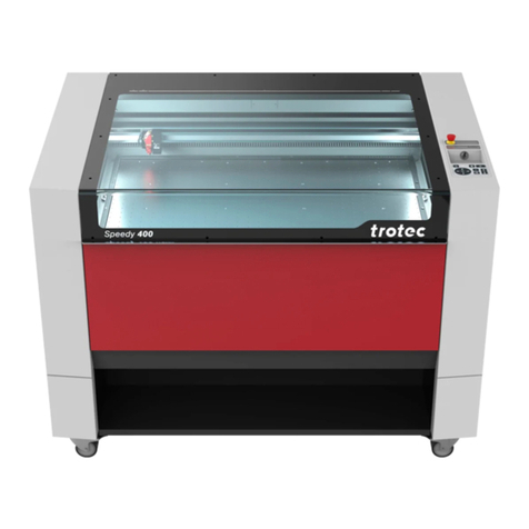
Trotec Speedy 500 User manual

Pre-Installation Instructions
8014 Trotec Speedy 500

Pre-Installation Instructions
8014 Trotec Speedy 500
Table of Contents
13/12/2011 Trotec Produktions- und Vertriebs GmbH_Linzer Strasse 156, A-4600 Wels, Austria, Technical Support 2 / 15
tel_+43 (0)7242 239-7000, fax_+43 (0)7242 239-7380, mailto: techsupport@troteclaser.com
Table of Contents
Table of Contents ...............................................................................................................2
1 Laser Machine Requirements.........................................................................................3
1.1 Transportation and Handling .....................................................................................................................3
1.2 Dimensions and Mass of machine.............................................................................................................3
1.3 Unloading of the crate and machine..........................................................................................................4
1.4 Floor plan for the Speedy 500....................................................................................................................5
1.5 Operating Environment and Safety ...........................................................................................................6
1.6 Electrical Requirements..............................................................................................................................7
1.7 Electrical Connection..................................................................................................................................9
1.8 Gas Requirements for Gas Kit .................................................................................................................10
2 Computer and Software Requirements .......................................................................11
2.1 Minimum Computer Configuration for JobControl................................................................................11
2.2 Minimum Computer Configuration for TroCAM.....................................................................................11
2.3 Minimum Computer Configuration for I-Cut...........................................................................................11
2.4 Software Recommendation......................................................................................................................12
3 Exhaust Requirements..................................................................................................13
4 Water Chiller Requirements..........................................................................................14
4.1 Cooling Requirements for laser tubes ....................................................................................................14
4.2 Electrical Requirements and other specifications for Trotec chillers .................................................14
4.3 General notes regarding Trotec chillers .................................................................................................14
4.4 Water Requirements for chiller and laser tube.......................................................................................14
5 Installation Preview.......................................................................................................15

Pre-Installation Instructions
8014 Trotec Speedy 500
Laser Machine Requirements
13/12/2011 Trotec Produktions- und Vertriebs GmbH_Linzer Strasse 156, A-4600 Wels, Austria, Technical Support 3 / 15
tel_+43 (0)7242 239-7000, fax_+43 (0)7242 239-7380, mailto: techsupport@troteclaser.com
1 Laser Machine Requirements
1.1 Transportation and Handling
Dimensions of wooden
crate (W x D x H)
2160 x 1810 x 1490 mm
85.5 x 71.5 x 59 inches
Forklift requirement for
unloading
minimum 1000 kg or 2200 lb
1.2 Dimensions and Mass of machine
Dimensions of the machine
(W x D x H)
1920 x 1280 x 1153 mm
76 x 50 x 45 in.
Mass of the machine 550 - 600 kg
1210 - 1320 lbs
(depending on laser power)
Min. door width 1300 mm
51 in.

Pre-Installation Instructions
8014 Trotec Speedy 500
Laser Machine Requirements
13/12/2011 Trotec Produktions- und Vertriebs GmbH_Linzer Strasse 156, A-4600 Wels, Austria, Technical Support 4 / 15
tel_+43 (0)7242 239-7000, fax_+43 (0)7242 239-7380, mailto: techsupport@troteclaser.com
1.3 Unloading of the crate and machine
The Speedy 500 is transported in a wooden crate.
A suitable fork-lift is required to unload from the courier vehicle and lift the machine off its pallet.
A powered screwdriver with cross-head bit is recommended for dismantling the wooden crate.
If possible keep the packaging in case the machine ever needs to be relocated or shipped for any
reason.
Perform the following steps to unpack the machine properly:
1 Dismantle top and rear of the crate. 2 Remove all tables and accessory found in the
slots on the rear.
3 Remove the front and side plates. 4 Remove the transportation safety device.
Front: mid, back: left, right, mid (PSU-vat)
5 Open door on the front door of
Speedy500 (10mm Allen-Key). 6 Follow the safety instructions!
Caution:
Lift only on indicated lifting points!
Lifting the machine on any
other point will cause
extensive damage.
Only lower the machine onto an even surface.
7
Lift Speedy 500 with forklift on
indicated lifting points. Adjust rollers
and feet as necessary.
8 Remove the transportation safety device of the
x-axis.
9 The machine must be allowed to stand for 24 hours before use.

Pre-Installation Instructions
8014 Trotec Speedy 500
Laser Machine Requirements
13/12/2011 Trotec Produktions- und Vertriebs GmbH_Linzer Strasse 156, A-4600 Wels, Austria, Technical Support 5 / 15
tel_+43 (0)7242 239-7000, fax_+43 (0)7242 239-7380, mailto: techsupport@troteclaser.com
1.4 Floor plan for the Speedy 500
It is necessary to have sufficient clear space to the sides, front and rear of the machine for
installation, operation and maintenance.
Top View
1000mm
39.37”
1000mm
39.37” 1000mm
39.37”
1000mm
39.37”
Rear View
Mains power inlet, PC connection and exhaust port locations.
Power
Connection
PC-
Connection
Head Exhaust-
Connection
Table Exhaust-
Connection
440mm
17.32”
Chiller, Gas,
Compressed Air inlet
190mm
7.48”
440mm
17.32”
115mm
4.53”

Pre-Installation Instructions
8014 Trotec Speedy 500
Laser Machine Requirements
13/12/2011 Trotec Produktions- und Vertriebs GmbH_Linzer Strasse 156, A-4600 Wels, Austria, Technical Support 6 / 15
tel_+43 (0)7242 239-7000, fax_+43 (0)7242 239-7380, mailto: techsupport@troteclaser.com
1.5 Operating Environment and Safety
Laser safety class Class 2
Class 4 with pass through option
Wavelength of the laser radiation 10.6 µm
Ambient room temperature
Humidity
MUST be between 15 and 25°C (59 and 77°F);
40% - 70%, not condensing
Follow the local laws and regulations regarding operation of laser machines.
It is important that the machine is installed in an appropriate operating environment. This will reduce
the risk of possible downtime plus increase performance and quality of output.
Operating outside of this temperature range can have a detrimental effect to the working life and/or
performance of the system, particularly the laser tube. If transporting the laser system from a very
cold or very hot environment to the proper operating environment, the laser system must not be
turned on before it has adjusted to the temperature conditions. Therefore, once the system has
been moved to the desired area it must be allowed to stand for 24 hours before use. Rapid
changes of temperature during operation can risk condensation forming within the laser tube and/or
electronics and increases the potential risk of electronic failure.
These guidelines must be followed to ensure a proper operating environment for the laser system.
Although conforming to these guidelines will greatly reduce the chance of a problem occurring, it
does not guarantee it. It is your responsibility to provide a proper operating environment.
•Dusty or dirty air environments can damage the laser system. Keep the laser system isolated
from any type of sandblasting, sanding equipment, or any other machinery or processes that
produce airborne particles.
•Avoid small, enclosed, non-ventilated areas. Some materials, after laser engraving or cutting,
continue emitting fumes for several minutes after processing. Having these materials present in
a confined, unventilated room can contaminate the room.
We recommend installing the laser system on a concrete floor. The floor underneath the laser
system should be flat within 3mm from wheel to wheel. An uneven surface may cause a twisting of
the main enclosure. This can cause motion system binding as well as engraving problems.
Pre-Installation Instructions
8014 Trotec Speedy 500
Laser Machine Requirements
13/12/2011 Trotec Produktions- und Vertriebs GmbH_Linzer Strasse 156, A-4600 Wels, Austria, Technical Support 7 / 15
tel_+43 (0)7242 239-7000, fax_+43 (0)7242 239-7380, mailto: techsupport@troteclaser.com
1.6 Electrical Requirements
Make sure that your electrical outlet is capable of providing the proper voltage, frequency and
amperage that the laser system requires.
We recommend having individual circuits for
•laser engraver
•extractor
•water chiller
Please install your computer to the same circuit as the laser engraver to prevent electromagnetic
interactions!
Every order has to include information regarding the desired frequency.
The following table provides information regarding power requirements, which depends on the laser
tube specification (“ac” = air-cooled tube, “wc” = water-cooled).
Laser Power
Voltage
Fuse
Frequency
Phases
Power
consumption
60Wac
208/230V
16A slow
50/60Hz
1
L,N,
Ground
(PE)
2100W
60Wwc
208/230V
16A slow
50/60Hz
1
L ,N ,
Ground
(PE)
1600W
75Wac
208/230V
16A slow
50/60Hz
1
L , N,
Ground
(PE)
2100W
85Wac
208/230V
16A slow
50/60Hz
1
L , N,
Ground
(PE)
2800W
95Wac
208/230V
16A slow
50/60Hz
1
L , N,
Ground
(PE)
2800W
Laser Power
Voltage
Fuse
Frequency
Phases
Power
consumption
105Wac
208/230V
16A slow
50/60Hz
1
L , N,
Ground
(PE)
3100W
120Wac
208/230V
16A slow
50/60Hz
1
L , N,
Ground
(PE)
3100W
120Wwc
208/230V
16A slow
50/60Hz
1
L , N,
Ground
(PE)
3100W
200Wwc
400V
16A slow
50/60Hz
3
L1,L2,L3,N,
Ground
(PE)
L – L: 400V
L - N: 230V
4500W
200Wwc US
208/230V
20A slow
50/60Hz
3
L1,L2,L3,
Ground
(PE)
L – L:
208/230V
4500W

Pre-Installation Instructions
8014 Trotec Speedy 500
Laser Machine Requirements
13/12/2011 Trotec Produktions- und Vertriebs GmbH_Linzer Strasse 156, A-4600 Wels, Austria, Technical Support 8 / 15
tel_+43 (0)7242 239-7000, fax_+43 (0)7242 239-7380, mailto: techsupport@troteclaser.com
The machine is supplied with the following cable for mains supply connection, depending on laser
tube specification and region.
60Wac 60Wwc 75Wac 85Wac 95Wac 105Wac 120Wac 120Wwc 200Wwc
EU 86956
USA 5664
UK 16369
39886
Part # Description Picture
86956 Europe CEEVII+C19 (250V/16A)
Cable length: 2,5 m / 8 ft
5664 USA NEMA 6-20+C19 (250V/20A)
Cable length: 2,5 m / 8 ft
16369 IEC309 Plug IP44 2P+E (220V/16A)
Cable length: 2 m / 6.5 ft
39886 CEE Plug 3x16A
Cable length: 5 m / 16 ft
Female connectors on machine side are the following:
60W – 120W: 200W:

Pre-Installation Instructions
8014 Trotec Speedy 500
Laser Machine Requirements
13/12/2011 Trotec Produktions- und Vertriebs GmbH_Linzer Strasse 156, A-4600 Wels, Austria, Technical Support 9 / 15
tel_+43 (0)7242 239-7000, fax_+43 (0)7242 239-7380, mailto: techsupport@troteclaser.com
1.7 Electrical Connection
DAMAGES FROM AN INADEQUATE OR INAPPROPRIATE POWER SOURCE ARE NOT COVERED
UNDER WARRANTY.
Noisy or unstable electricity as well as voltage spikes can cause interference and possible damage
to the electronics of the laser system. It is better to connect the laser system to a dedicated
electrical line.
It is highly recommended that you use a surge protection device to protect your equipment.
If electrical power fluctuations, brown outs, or power outages are a problem in your area, an
electrical line stabilizer, UPS (Uninterruptible Power Supply), or backup generator may be required.
If installing any of these devices, make sure that they meet the electrical requirements of the laser
system.
It is your responsibility to provide a suitable electrical supply.

Pre-Installation Instructions
8014 Trotec Speedy 500
Laser Machine Requirements
13/12/2011 Trotec Produktions- und Vertriebs GmbH_Linzer Strasse 156, A-4600 Wels, Austria, Technical Support 10 / 15
tel_+43 (0)7242 239-7000, fax_+43 (0)7242 239-7380, mailto: techsupport@troteclaser.com
1.8 Gas Requirements for Gas Kit
An external gas or compressed air supply is required for machines with gas assist as well as for
applications where the amount of air provided by the internal compressor is too small.
The following requirements must be met:
The gas/air must be
•free of mechanical particles (dust)
•free of liquid substances (oil, water)
•flow rate: 150 l/min (40gpm)
•max. pressure: 10 bar (145 psi)
•connected with a push fitting with 6 mm / 0.23” outside diameter.
Gases to be used:
•Compressed air
•Argon
•Nitrogen
•Inert gas

Pre-Installation Instructions
8014 Trotec Speedy 500
Computer and Software Requirements
13/12/2011 Trotec Produktions- und Vertriebs GmbH_Linzer Strasse 156, A-4600 Wels, Austria, Technical Support 11 / 15
tel_+43 (0)7242 239-7000, fax_+43 (0)7242 239-7380, mailto: techsupport@troteclaser.com
2 Computer and Software Requirements
Remember that the laser system is an output device just like a printer. With a higher specified
computer you can create graphics and manipulate your software faster and process data faster to
the laser, increasing your productivity.
Also in order to install and configure software during installation, full administrative rights access is
required.
2.1 Minimum Computer Configuration for JobControl
•Windows 7® 32/64-bit or
Windows Vista® 32/64-bit (with Service Pack 1 or later) or
Windows® XP 32/64-bit (with Service Pack 2 or later)
•512 MB of RAM
•400 MB of hard disk space
•Pentium® 1 GHz processor or AMD Athlon™ XP
•1024 x 768 or better monitor resolution
•24-bit color depth graphics card
•1 free USB interface
•CD drive
•Mouse
2.2 Minimum Computer Configuration for TroCAM
•Windows® XP Service Pack 3 or
Windows 7® 32/64-bit
•2 GB RAM for 32 bit / 6 GB RAM for 64 bit
•120 GB hard disk space
•Intel i5 / i7 Processor
•DVD drive
•Serial Port (preferred) or
USB port for connection between PC and Laser
2.3 Minimum Computer Configuration for I-Cut
•Windows 7® 32/64-bit or
Windows Vista® 32-bit (with Service Pack 1 or later) or
Windows® XP 32-bit (with Service Pack 2 or later)
•1 GB RAM
•500 MB hard disk space
•2 GHz Processor
•PCI-Express-Slot X1 (22 + 14 Pins)
•USB port for I-Cut Dongle
•Serial port (preferred) or
USB port for connection between PC and Laser

Pre-Installation Instructions
8014 Trotec Speedy 500
Computer and Software Requirements
13/12/2011 Trotec Produktions- und Vertriebs GmbH_Linzer Strasse 156, A-4600 Wels, Austria, Technical Support 12 / 15
tel_+43 (0)7242 239-7000, fax_+43 (0)7242 239-7380, mailto: techsupport@troteclaser.com
2.4 Software Recommendation
The following is a list of recommended software programs.
•Graphics Software - CorelDraw version X3 to X5 for raster engraving
•Bitmap Editing Software – Corel PhotoPaint (supplied with CorelDraw graphics suite)
•CAD/CAM Software - troCAM – also can convert raster to vector images.
•Camera software - I-Cut
Trotec software has been designed to interpret objects either as engraving or as cutting objects.
If you use the Trotec printer driver interface and the line thickness (object dimension) exceeds
0.2 mm items will be engraved, if the smallest possible line thickness that your Desktop publishing
program offers is chosen (e.g. 0.001mm/hairline in Corel Draw) they will be cut.
Additionally, you have the possibility to use up to 16 colors and define a process for each color.
This means you can engrave with different power and cut with different depths in one run.
If you use CAD software for the design and transfer data via the HPGL interface, all lines will be
interpreted as cut lines.
When a software company updates their version of their programs, it can sometimes cause conflicts
with our printer driver/manager. Our programmers constantly test new software programs and
updated versions for compatibility. We will update our software/firmware to address issues that we
have control of. For bugs or problems with your software not related to the laser system, please
contact the software manufacturer.

Pre-Installation Instructions
8014 Trotec Speedy 500
Exhaust Requirements
13/12/2011 Trotec Produktions- und Vertriebs GmbH_Linzer Strasse 156, A-4600 Wels, Austria, Technical Support 13 / 15
tel_+43 (0)7242 239-7000, fax_+43 (0)7242 239-7380, mailto: techsupport@troteclaser.com
3 Exhaust Requirements
Trotec advises to use the Atmos Duo Plus for the Speedy 500.
If only a Cutting table is installed, a VENT 3000 would be sufficient.
The laser may only be operated with properly installed and operating exhaust system.
Damage to the system caused by the use of no or improper extraction equipment will
not be covered by warranty.
Fumes and dust created during cutting or engraving have to be exhausted properly.
Some materials when cut or engraved can produce fumes that are hazardous in
concentrated amounts.
The life time of optics and mechanical components will be reduced by fumes and dust
accumulating in the machine. This will be avoided by a capable exhaust system.
The cutting quality will be reduced by fumes and dust accumulating in the machine.
This will be avoided by a capable exhaust system.
The laser power interacting with the work-piece will be reduced by fumes and dust
accumulating in the machine. This will be avoided by a capable exhaust system.
Depending on the type of table installed in the machine the exhaust requirements and
recommended Trotec exhaust systems for standard applications are:
Flow rate Pressure
Atmos
Mono
Atmos
Duo
Vent
3000
Vent
HP
Head Exhaust (45mm) 50 m³/h 5300 Pa 9989
Vacuum table (75mm) 250 m³/h 3900 Pa 8989
Cutting table (75mm) 350 m³/h 1500 Pa 8999
Standard table Not applicable (Table Exhaust inactive)
Monitoring point for flow-rate and pressure is at the exhaust port at the laser machine. Pressure
loss by hoses / pipes or filter parts of the exhaust has to be determined and additionally calculated
when selecting a proper exhaust.
The exhaust power which is available for the application will be reduced by e.g.
bending, small hose diameters and long hoses.
Therefore, avoid bending, keep hoses as short as possible and use hoses with
diameters as large as possible.
Applications generating large amounts of dust or fumes may require a stronger
exhaust system.
Also the use of separate exhaust systems for head and table exhaust may be
necessary.
It is absolutely necessary to consult your distributor in such cases.

Pre-Installation Instructions
8014 Trotec Speedy 500
Water Chiller Requirements
13/12/2011 Trotec Produktions- und Vertriebs GmbH_Linzer Strasse 156, A-4600 Wels, Austria, Technical Support 14 / 15
tel_+43 (0)7242 239-7000, fax_+43 (0)7242 239-7380, mailto: techsupport@troteclaser.com
4 Water Chiller Requirements
For machines fitted with water-cooled laser tubes, you need a water cooling unit.
4.1 Cooling Requirements for laser tubes
Laser power [W]: 60 120 200
Minimum cooling capacity [W] 500 2300 4000
Minimum flow rate [l/min]
at 18 to 22°C 6 10 11,4
Maximum pressure [bar] 4,2 4,2 4,2
Pressure loss [bar] 1,2 - 1,4
4.2 Electrical Requirements and other specifications for Trotec chillers
EU US
Laser power [W] 60 120 200 60 120 200
Voltage [V] 1x230 1x230 1x230 1x115 1x115V 1x230
Frequency [Hz] 50/60 50/60 50 60 60 50/60
Phases
L, N,
Ground
L, N,
Ground
L, N,
Ground
L, N,
Ground
L, N,
Ground
L, N,
Ground
Power consumption [W] 900 W 1800 W 3000 900 1800 3000
4.3 General notes regarding Trotec chillers
All chillers are delivered with Europe CEEVII+C19 plugs.
The coolant temperature has to be between 18 and 25°C.
If temperature falls below this range, the chiller might not be ready for operation and the coolant has
to be warmed.
4.4 Water Requirements for chiller and laser tube
Please, use normal tap water as coolant. The use of de-ionized, de-mineralized or distilled water is
not recommended and can destroy the laser tube.
Ideal water quality
Ph-value: 7-9
Alkalinity (°dH): <1
Conductivity: <300 μS/cm
Chloride content: <20 mg/L
Hardness (°dH): <0,1
Organic germs: <1000 KBE/ml
In case of deviations of water quality, it is recommended to us softening agents, corrosion inhibitors
or biocide additives.

Pre-Installation Instructions
8014 Trotec Speedy 500
Installation Preview
13/12/2011 Trotec Produktions- und Vertriebs GmbH_Linzer Strasse 156, A-4600 Wels, Austria, Technical Support 15 / 15
tel_+43 (0)7242 239-7000, fax_+43 (0)7242 239-7380, mailto: techsupport@troteclaser.com
5 Installation Preview
The following list gives a preview of the installation procedure. This will assist you to prepare
yourself and your premises for the arrival of your new Speedy 500.
1.) Tools for initial installation
a. Power screwdriver + set of bits
b. Measuring tape
c. Double ended spanner (Wheels: 22mm Feet: 24mm)
d. Water-level – min. 20cm
2.) Set-up
a. Fork lift (compare label [lift here])
b. Footprint
c. Unpack (take care on tables)
d. Retention time 24h at ambient temperature (unpacked)
e. Alignment with level (water level – min. 20cm)
3.) Connecting
a. Electricity
b. Gas
c. Cooling
d. Exhaust
4.) Initial operation
a. Activate peripherals (Electricity, gas, cooling, exhaust)
b. Unlock emergency switch
c. Main switch (striking sound)
d. Turn on key-switch
e. Machine starts - initializing
5.) Factory Setting check
a. Check optics (Lens, mirrors) to be clean
b. Check laser beam
c. Check table adjustment
d. Check air assist and gas
e. Check offset (0/0)
f. Check exhaust power
6.) Engraving sample / Cutting sample
a. Check correction factors, overtook, and tickles with any engraving job
b. Check laser correction with a cutting job
7.) End customer training according to user manual.
Other manuals for Speedy 500
2
This manual suits for next models
1
Table of contents
Other Trotec Printer manuals

Trotec
Trotec 8012 Speedmarker CL User manual

Trotec
Trotec Speedy 100 User manual

Trotec
Trotec Speedy 300 fiber User manual

Trotec
Trotec Speedy 100 User manual

Trotec
Trotec Speedy 400 User manual

Trotec
Trotec Speedy 400 flexx User manual

Trotec
Trotec Speedy 360 flexx User manual

Trotec
Trotec SpeedMarker 700 FL User manual

Trotec
Trotec Speedy 360 flexx User manual