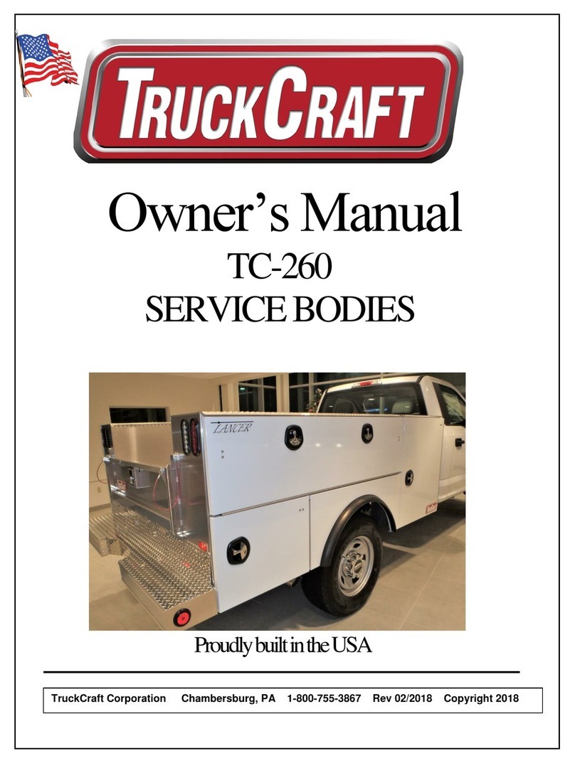
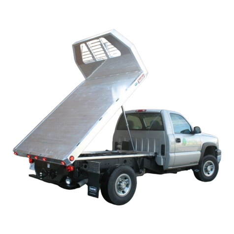
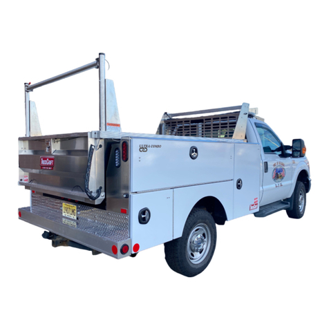
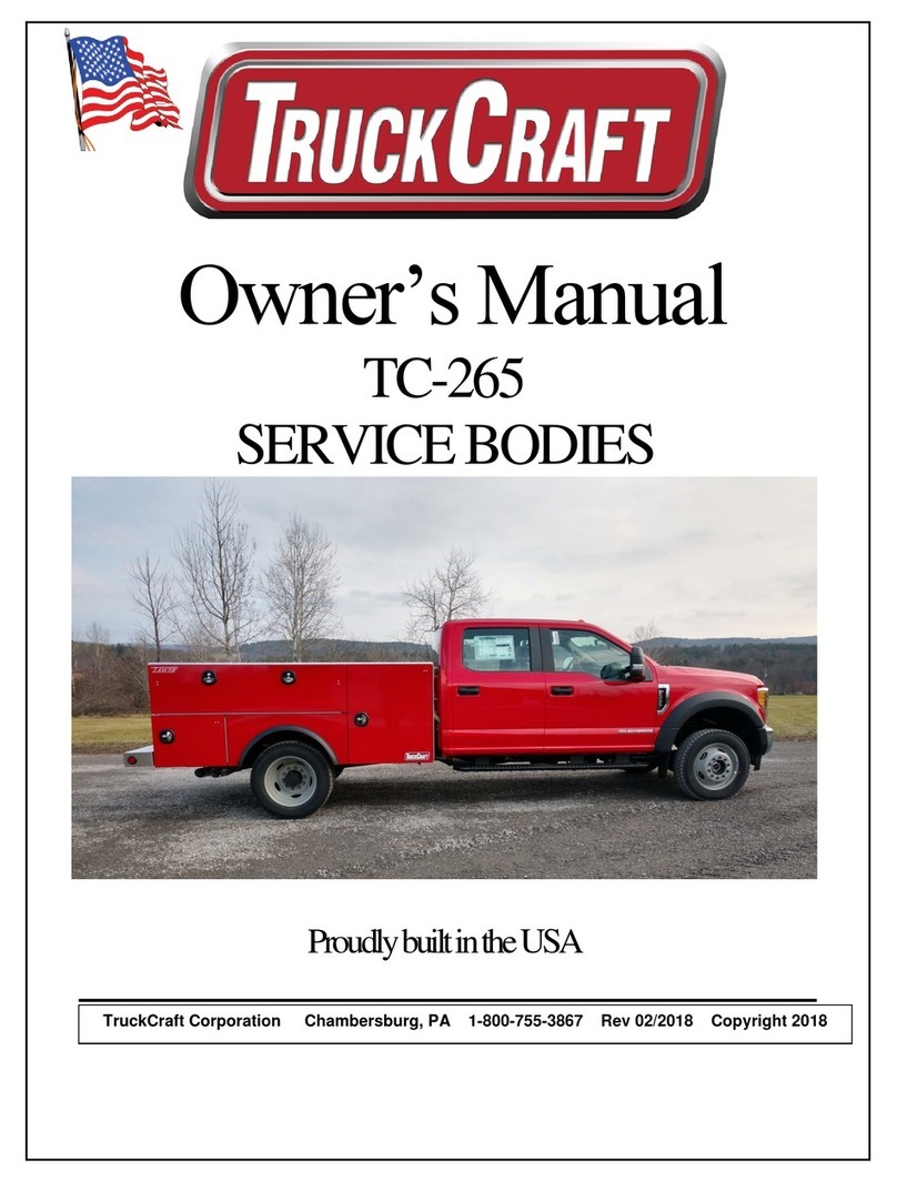
TruckCraft TC-503 User manual

Copyright 2018 TruckCraft Corporation Rev. 3/2018
TruckCraft Corporation
5751 Molly Pitcher Hwy
South
Chambersburg, `PA 17202
TC-503 Dump Bodies
Tel. (800) 755-3867
Fax. (717) 375-2975
E-Mail:
sales@truckcraft.com
Web: www.truckcraft.com
Table of Contents
Preface……………………………………………………… 1
Ordering Repair Parts…………………………………………… 1
Safety Informaon……………………………………………….. 2
Cerfying and Labeling Chassis-Cabs …………………………. 3 & 4
Mounng Instrucons……………………………………………. 5, 6 & 7
Maintenance……………………………………………………… 8
Parts Lists:
Hoist & Sub-Frame Grease Fing Chart (I5-08084) 9 & 10
Hoist & Sub-Frame 6” Cyl. (D1-04829)……..………… 11 & 12
TC-503 Storm 9’-9” or 11’-5” (D1-06527)……………… 13
TC-503 9’-9” or 11’-5” Body w/ Side Door & Rear Barn Doors
-50” Sides (D1-06516)…………………………………………...…… 14 & 15
TC-503 9’-9” or 11’-5” Body w/ No Side Doors-50” Sides
(D1-06788) ………………………………………………………………… 16 & 17
TC-503 9’-9” or 11’-5” Body w/ Side Door-40” Sides
(D1-06639)…………………………………………………………………. 18 & 19
TC-503 T’gate w/ Coal chute & Barn Doors (D2-06633).. 20
Tarp Assy-170”Lg./Landscaper Body (D2-06321)…………. 21
Cabguard Installaon/40” length (D2-06460) (Opon) 22
Hitch Plate & Bumper STD. (D2-05648) Opon) ……….. 23
Major Product Components……………………………………… 24 & 25
TruckCra Warranty Registlaon……………………………… 26
TruckCra Warranty Cercate………………………………… 27, 28 & 29
NOTE: To acvate the Warranty on your new TC-503 go online to
www.truckcra.com or contact your nearest TruckCra dealer.
The TruckCra hoists are designed for use with TruckCra’s 9’-9” and
11’-5” aluminum dump bodies.

Copyright 2018 TruckCraft Corporation Rev. 3/2018
TruckCraft Corporation
5751 Molly Pitcher Hwy
South
Chambersburg, `PA 17202
TC-503 Dump Bodies
Tel. (800) 755-3867
Fax. (717) 375-2975
E-Mail:
sales@truckcraft.com
Web: www.truckcraft.com
Preface
Read and understand all secons of this manual prior to
installing or operang the TruckCra hoist.
This manual contains information for the installation, operation, and mainte-
nance of the TruckCraft TC-503 Hoist, Sub-Frame and Dump Body. Proper care
and operation of the unit will assure years of dependable service. Your local
TruckCraft Dealer will instruct you in its general operation. TruckCraft Corpora-
tion will be glad to answer any questions that may arise regarding the operation
of your unit.
Ordering Repair Parts
When service is necessary, your local TruckCraft dealer can provide assis-
tance. Always obtain original TruckCraft replacement parts from your dealer.
Substitute items could affect the performance and warranty of the unit. Dealers
in your area can be found on the web at www.TruckCraft.com.
When ordering parts the product serial number, and description or part number
of parts needed are required. The product serial number is located on
the drivers side of the front face (behind truck cab) of the dumper
body.
Product Serial Number: ___________________________
Date of Purchase: _____________________________
Purchased From: _____________________________
TruckCraft Telephone #800.375.3867 or 717.375.2900
TruckCraft Fax #717.375.2975
Method of shipping parts to be specified such as customer pickup, UPS, Com-
mon Carrier, Parcel Post or Air Freight. All orders to be confirmed in writing, or
faxed, to insure proper understanding of request.
Having preventative maintenance parts on hand could save valuable time.
Improvements and Changes
Because TruckCraft strives to continually improve our products, we
reserve the right to make changes and improvements wherever practical,
without obligation to make those same changes or improvements to the
equipment already sold. Photographs used in this manual may not be up-
to-date with current design changes.
1

Copyright 2018 TruckCraft Corporation Rev. 3/2018
TruckCraft Corporation
5751 Molly Pitcher Hwy
South
Chambersburg, `PA 17202
TC-503 Dump Bodies
Tel. (800) 755-3867
Fax. (717) 375-2975
E-Mail:
sales@truckcraft.com
Web: www.truckcraft.com
Safety Information
Observe the following safety procedures during the use of the hoist and dump
body: Before operating read and understand all information furnished with
your hoist and in this manual.
✓ Keep hands, feet and clothing away
from moving parts.
✓ Keep hinge pins and bushings well
greased-inspect regularly for proper
operation during rotation.
✓ Never exceed the rating of the hoist ,
truck, axles, or tires. Make certain
the load is evenly distributed.
✓ Never work under a raised body unless the body is supported
by blocking or propped in the raised position. Always unload the body prior
to using the prop.
✓ Operate the hoist only
when the truck is on a firm,
level surface.
✓ Always inspect the area
around the truck for safe
dumping prior to operating
the hoist.
✓ Do not move the truck with the body in a raised position.
✓ Always release the tailgate pins prior to raising the dump body when it is
loaded. The tailgate pins should not be released with a load against the
tailgate.
✓ Store the remote control in a location that assures that no object can come
in contact with the raise button unintentionally.
✓ Before raising the dumper, check for adequate overhead clearance. Be
alert for overhead electrical wires.
✓ Always ensure that the red warning light is off, indicating that the body is all
the way down, before operating the truck.
✓ Regularly check and tighten all fasteners to the recommended torque val-
ues in the Torque Chart shown below.
✓ Maximum hydraulic pressure is factory set at 3200 PSI. Tampering with
this setting can damage hydraulic components and result in system failure.
✓ Use automatic transmission fluid in
the hydraulic reservoir. Check reg-
ularly and keep clean.
2
FIGURE 1
FIGURE 2
FIGURE 3
Size Grade 5 (Lb-Ft) Grade 8 (Lb-Ft)
1/4-20 6-7 10-11
1/4-28 8-9 11-12
5/16-18 14-15 21-22
3/8-16 24-26 37-40
1/2-13 60-65 90-100
5/8-11 122-130 180-190
3/4-10 220-230 315-330
Torque Chart - Steel Fasteners

Copyright 2018 TruckCraft Corporation Rev. 3/2018
TruckCraft Corporation
5751 Molly Pitcher Hwy
South
Chambersburg, `PA 17202
TC-503 Dump Bodies
Tel. (800) 755-3867
Fax. (717) 375-2975
E-Mail:
sales@truckcraft.com
Web: www.truckcraft.com
Cerfying and Labeling Chassis-Cabs aer
mounng TruckCra dump body
New chassis-cabs are supplied by the manufacturer with incomplete vehi-
cle documentation (IVD). According to the National Highway Traffic Admin-
istration, ”NHTSA”, regulations a “manufacturer” is a person who performs a
manufacturing operation on a new incomplete vehicle. A Final Stage Manufac-
turer is a person who performs such manufacturing operations on an incom-
plete vehicle that it becomes a complete vehicle. It is the responsibility of this
Final Manufacturer to affix an approved label to the vehicle certifying that the
vehicle meets all applicable Federal Motor Vehicle Safety Standards. Regula-
tions also require certification in many instances when mounting a dump body
on a used chassis-cab.
It is strongly recommended that anyone contemplating mounting a Truck-
Craft dump body and not familiar with the regulations obtain a copy of the Na-
tional Truck Equipment Association’s, “NTEA’s”, “Vehicle Certification Guide”.
Thoroughly read and understanding all sections of this guide before attempt-
ing to certify a completed vehicle. The “Guide”, free to NTEA members, can
be purchased on the NTEA website, www.NTEA.com.
Below are answers/recommendations to key certification questions:
1) If the end-user purchases a new cab-chassis and mounts the dump body,
does the completed vehicle need to be certified?
Per the NTEA “Guide” page 9B, “When the ultimate customer purchases an
incomplete vehicle and installs additional equipment, he becomes, in effect, a
manufacturer and thus is subject to the certification and registration require-
ments of the Act.”
2) What must an end-user/manufacturer do in order to be able to certify a
completed vehicle?
Per the NTEA “Guide” pages 1C and 2C, Chapter 1, all manufacturers need to
register with the NHTSA on form (49 CFR 566) - a copy of which is included in
the book.
3) Will the chassis-cab safely handle the weight of the dump body and pay-
load?
The Incomplete Vehicle Manual usually contains information on calculating
maximum completed vehicle weights and acceptable horizontal and vertical
combined centers of gravity for compliance to the Federal Motor Vehicle Safe-
ty Standards. If not supplied with the chassis-cab, this information should be
obtained from the truck dealer and calculations need to be performed to make
sure limits are not exceeded. Based on the maximum axle weight limitations,
3

Copyright 2018 TruckCraft Corporation Rev. 3/2018
TruckCraft Corporation
5751 Molly Pitcher Hwy
South
Chambersburg, `PA 17202
TC-503 Dump Bodies
Tel. (800) 755-3867
Fax. (717) 375-2975
E-Mail:
sales@truckcraft.com
Web: www.truckcraft.com
calculations should also be run to determine the maximum payload capacity
of the dump body.
4) What are the steps to certifying and labeling the completed vehicle?
Chapter 5, pages 1F through 4F, of the NTEA “Guide” outline this procedure
when certification is within the guidelines of the Incomplete Vehicle Manual.
Certification labels, item #2159, can be purchased from the NTEA in quanti-
ties of 100 labels per order.
5) What are the Tire and Loading label requirements?
Vehicles with a gross vehicle weight rating (GVWR) of 10,000# or less are
required to have a Tire and Loading label. Chapter 7, 1H through 4H, of the
NTEA “Guide” outlines the procedure for calculating the data on this label.
This label, item #1220, can also be purchased in quantities of 60 from the
NTEA.
4

Copyright 2018 TruckCraft Corporation Rev. 3/2018
TruckCraft Corporation
5751 Molly Pitcher Hwy
South
Chambersburg, `PA 17202
TC-503 Dump Bodies
Tel. (800) 755-3867
Fax. (717) 375-2975
E-Mail:
sales@truckcraft.com
Web: www.truckcraft.com
Mounting Instructions
CAUTION: Verify lifting and support devices can support the hoist, sub frame,
and dump body combined weight before picking up the assembly.
The hoist, sub-frame and dump body are normally shipped assembled and
ready to install on a truck frame-see Figure 4. Truck manufacturers recommend
that the sub-frame does not contact the top of the frame. A gap can be estab-
lished by attaching 1/4” thick wooden strips on top of the frame or installing a
spacer layer of adhesive backed, high strength neoprene rubber on top of the
frame. However, solid connections between the truck frame and the sub-frame
are required at the location where the hoist pins to the sub-frame and at the rear
of the frame. When mounting with a 1/4” gap, the steel spacers supplied with
the kit need to be
installed between
the truck frame
and the sub-frame
at the hoist mount
location-see Detail
A. This spacer can
be eliminated if the
sub-frame is
mounted directly
on top of the truck frame with no space between the two.
1. Set the assembly on top of the frame or spacer and position it a minimum of
3.5” from the cab as shown above in Figure 4. Always make sure there is a
solid connection between the sub-frame and the truck frame at the rear in
the dump body pivot area and the hoist mount area shown in detail “A”. If the
rear pivot centerline extends beyond the rear of the frame, an angle iron
brace or similar structure can be welded across the back of the frame to sup-
port the pivot.
2. Position the sub-frame mounting brackets along the sides of the frame in an
area where the brackets do not interfere with existing frame bolts or hard-
ware-see Figure 5. Flipping the brackets or moving to alternate holes drilled
in the sub-frame usually eliminates interference. However, addional holes can
Make sure there is solid contact between the frame and sub-frame at the rear mount.
5

Copyright 2018 TruckCraft Corporation Rev. 3/2018
TruckCraft Corporation
5751 Molly Pitcher Hwy
South
Chambersburg, `PA 17202
TC-503 Dump Bodies
Tel. (800) 755-3867
Fax. (717) 375-2975
E-Mail:
sales@truckcraft.com
Web: www.truckcraft.com
be drilled in the sub-frame
as required. Use shims sup-
plied to fill any gaps be-
tween the mounting brackets
and the frame or sub-frame.
Mark the location for mount-
ing holes in the frame and
drill 8 holes (12 on TC-430)
21/32” diameter for 5/8”
grade 8 bolts supplied.
Caution: Be careful of wir-
ing, brake lines, etc. inside
frame when drilling. Install bolts, nuts and 2 washers per hole and torque
to 180 FT-LBS.
3. Route control cable into cab and install remote control box in an area
where the up button will not be unintentionally bumped.
4. Route power supply cable to battery and hook up leads to battery.
5. Make sure all blocking and tie-downs used for shipping are removed. Acti-
vated the remote control up button and carefully raise the body. Do not
reach under or place any body parts under the dump body. Raise the
body up about half
way to about 30 de-
grees from horizon-
tal. Rotate the safe-
ty prop counter-
clockwise until it
rests on the angle
stop on the hoist-
see figure 6. Care-
fully lower the hoist
until the cross shaft
of the hoist rests on
the prop. Do not
power down the
hoist after the
shaft rests on the
prop. With the prop
in this position it is
now safe to work under the dump body.
CAUTION:
✓ The TruckCraft assembly is designed to bolt to the truck frame. No weld-
ing is required. Do not weld any part of this assembly to the truck
frame.
✓ Openings have been provided in the side of the sub-frame for fuel tank
fill spouts. If additional holes are required in the sub-frame, the holes
must be a maximum of 2.5” in diameter and centered in the web. Never
6

Copyright 2018 TruckCraft Corporation Rev. 3/2018
TruckCraft Corporation
5751 Molly Pitcher Hwy
South
Chambersburg, `PA 17202
TC-503 Dump Bodies
Tel. (800) 755-3867
Fax. (717) 375-2975
E-Mail:
sales@truckcraft.com
Web: www.truckcraft.com
6. With the safety prop supporting the dump body and the truck level, check
the depth of the oil in the hydraulic reservoir. The depth of the fluid in the
tank at this position should be 3”. Use automatic transmission fluid only to
fill the reservoir to this level.
7. Apply grease at twelve grease zerks:
See HOIST & SUBFRAME GREASE FITTING CHART (I5-080854) for
location of the fittings.
8. Install the light, mount bracket and decal shown in figure 7 on the dash in-
side the cab of the truck. Using
the fuse holder, wire the light to
the dump switch mounted on
the front of the sub-frame
across from the hydraulic reser-
voir. Use the schematic shown
in figure 8 to connect the wir-
ing. Note: Wire not supplied by
TruckCraft.
9. Place the two decals A4-04684
and A4-04685 inside the cab
on the dash in an easy to read location.
10.Connect the marker light wiring harness to the truck wiring.
11.Push the remote control up but-
ton. Raise the hoist high
enough to drop the safety prop
back into its storage position.
Cycle the hoist through the
complete stroke of the tele-
scope cylinder a couple times to
make sure everything works
properly.
Warning: Never use the safety prop to support a loaded deck. Never posion
yourself under a loaded deck.
Fuse
Pilot
Hot Wire
From Truck
Electrical
System
Dash
Dump
Switch
Ground
Figure 8: Dump Bed Raised
Lamp Wiring Diagram
Lamp
Connecting wiring
by installer.
7

Copyright 2018 TruckCraft Corporation Rev. 3/2018
TruckCraft Corporation
5751 Molly Pitcher Hwy
South
Chambersburg, `PA 17202
TC-503 Dump Bodies
Tel. (800) 755-3867
Fax. (717) 375-2975
E-Mail:
sales@truckcraft.com
Web: www.truckcraft.com
Maintenance
1. Check hydraulic reservoir monthly and add oil as required, more fre-
quently under heavy use. Every two to three years, depending on the use,
drain the system and replace with clean fluid. Use Dexron Automatic
Transmission fluid only.
2. Apply grease to all rotating parts every six months minimum, more of-
ten under heavy use. Apply grease at all twelve grease fittings.
3. Depending on frequency of use, check hydraulic reservoir level and
add Check to make sure that the bed up warning light illuminates when
the bed begins to raise. Adjust switch or replace bulb as required.
4. Depending on frequency of use, check all bolts for proper tightness
and torque.
8
Table of contents
Other TruckCraft Automobile Accessories manuals
Popular Automobile Accessories manuals by other brands

ULTIMATE SPEED
ULTIMATE SPEED 279746 Assembly and Safety Advice

SSV Works
SSV Works DF-F65 manual

ULTIMATE SPEED
ULTIMATE SPEED CARBON Assembly and Safety Advice

Witter
Witter F174 Fitting instructions

WeatherTech
WeatherTech No-Drill installation instructions

TAUBENREUTHER
TAUBENREUTHER 1-336050 Installation instruction


