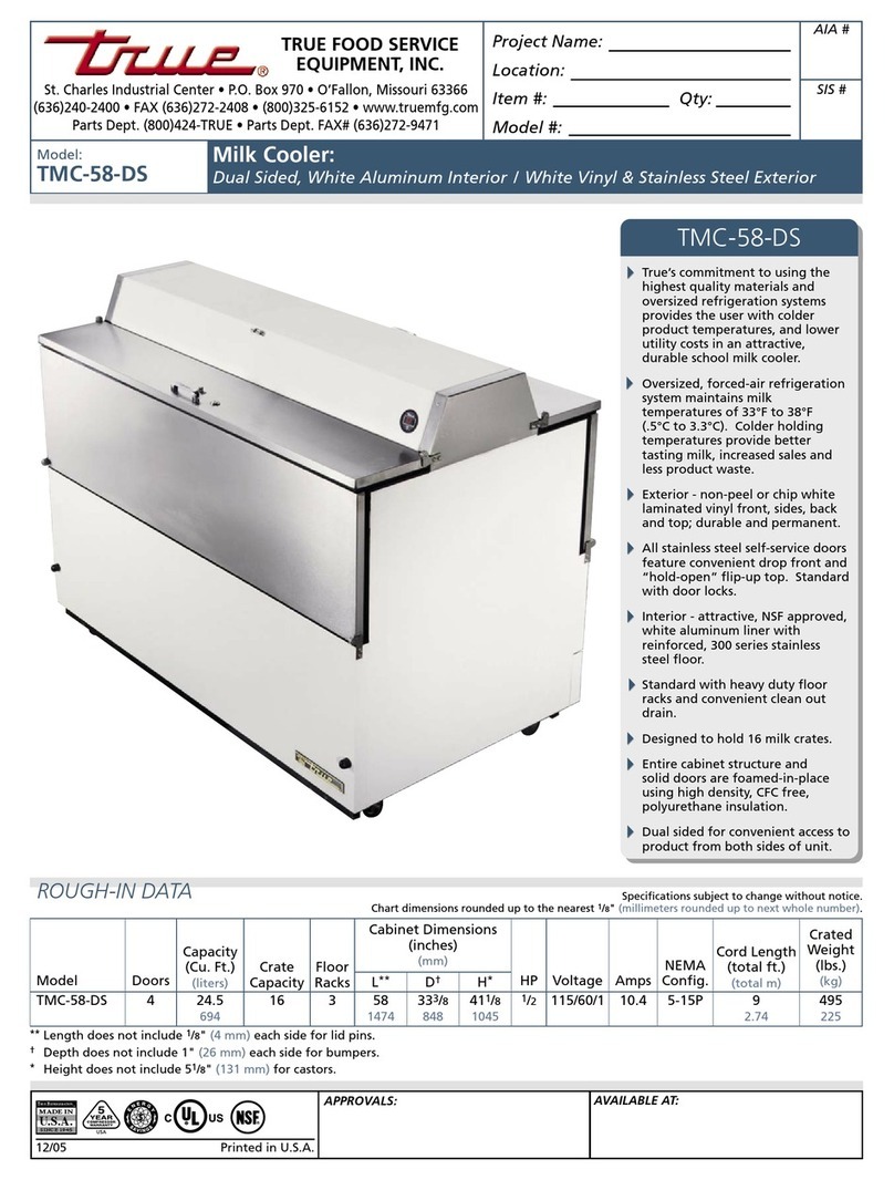
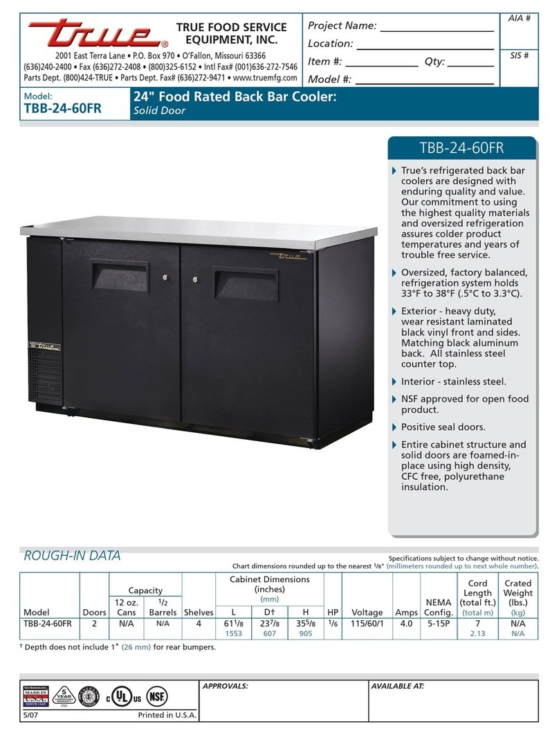
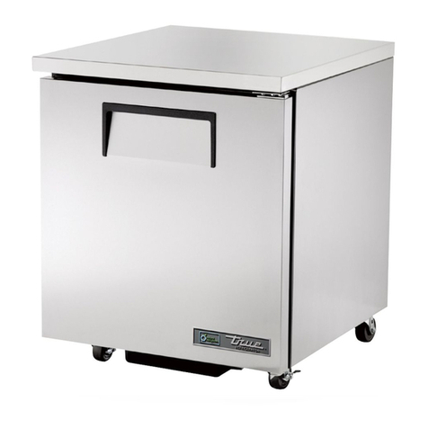
True TWC-24-OP User manual

WINE AND BEVERAGE CABINET USE AND CARE MANUAL
WINE CABINETS, BEVERAGE CENTERS
AND UNDERCOUNTER REFRIGERATORS
USE AND CARE MANUAL / INSTALLATION INSTRUCTIONS
www.true-residential.com
TWC, TBC, TUR Models (All overlay models - OP/OPG included)


WINE AND BEVERAGE CABINET USE AND CARE MANUAL
1
CONTENTS
Ownership 2
Safety Precautions 2
Disposal of Old Refrigerator 2
CFC Disposal 2
Uncrating 3
Cabinet Cleaning 3
How to Connect to Electricity 4
Leveling Refrigeration Equipment 4
Installing Anti-Tip Brackets 5
Overlay Models Only - OP/OPG 6-13
Installing True Signature Louver Grill 14-15
Start-up & Temperature Control 16
Shelving Operation 16-17
Drawer Divider Installation & Operation 17
General Maintenance 18
Replacement Parts 18
Installation Specifications (TWC, TBC, & TUR Door Units) 19
Installation Specifications (TUR Drawer Units) 20
TUR Plan View 21
Tapper Unit Installation under counter tops 22
Installing Draft Standard and Hook Up 23-24
Pressure 25
Tapping 25
Draft Beer Problems 25
Changing CO2 & Pressure Adjustment 26
Cleaning Instructions for Draft Towers 27
Troubleshooting 28
Frequently asked Questions 29
Stainless Steel Equipment Care and Cleaning 30
Warranty 31
Specifications are subject to change without notice.
UNCRATING INFORMATION / INSTALLATION MANUAL

WINE AND BEVERAGE CABINET USE AND CARE MANUAL
2
OWNERSHIP
To ensure that your unit works properly from the first day, it
must be installed properly. We highly recommend a trained
refrigeration mechanic and electrician install your True unit.
The cost of a professional installation is money well spent.
Before you start to install your True unit, carefully inspect it for
freight damage. If damage is discovered, immediately file a
claim with the delivery freight carrier. True is not responsible
for damage incurred during shipment.
If you have any questions about the installation, please contact
your True dealer or True Technical Service Department at 1-800-
325-6152. Please have your model and serial number(s) available
when you call our Service Department.
SAFETY PRECAUTIONS
• This refrigerator must be properly installed and located in
accordance with the installation instructions before it is used.
• Do not allow children to climb, stand or hang on the shelves
in the refrigerator. They could damage the refrigerator and
seriously injure themselves.
• Do not store or use gasoline or other ammable vapors and
liquids in the vicinity of this or any other appliance.
• Keep hands away from the “pinch point” areas (gaps between
the doors and between the doors and cabinet). Small areas
are not necessarily safe.
• Unplug the refrigerator before cleaning and making repairs.
NOTE: We strongly recommend that any servicing be
performed by a qualified individual.
• Setting temperature control to off removes power from the
condensing unit, it does not remove power from other circuits
(for example, interior lights).
• It is recommended to store the keys to the door lock away from
the cabinet to prevent accidental entrapment.
PROPER DISPOSAL OF THE OLD
REFRIGERATOR
Child entrapment and suffocation are not problems of the past.
Junked or abandoned refrigerators are still dangerous, even if
they will sit for “just a few days”. If you are getting rid of your old
refrigerator, please follow the instructions below to help prevent
accidents.
Before you throw away your old refrigerator or freezer:
• Take off the doors.
• Leave the shelves in place so that children may not easily
climb inside.
CFC DISPOSAL
Your old refrigerator may have a cooling system that used CFC’s
(chlorouorocarbons). CFCs are believed to harm stratospheric
ozone. If you are throwing away your old refrigerator, make sure
the CFC refrigerant is removed for proper disposal by a qualified
service. If you intentionally release this CFC refrigerant, you can
be subject to fines and imprisonment under provisions of the
environment legislation.

WINE AND BEVERAGE CABINET USE AND CARE MANUAL
3
UNCRATING
Tools Required:
• Cutting utensil (utility knife)
• Hammer
• Crowbar
• Phillips head screwdriver
The following procedure is recommended for uncrating the unit:
A. Move your unit as close to the final location as possible before
removing the wooden skid.
B. Remove nails securing cardboard box to the wooden skid.
Then discard any outer packaging (cardboard, clear plastic).
(See images 1-3). Inspect for concealed damage. Again,
immediately file a claim with the freight carrier if there is damage.
IMPORTANT - Remove wooden block with Phillips head
screw driver before removing refrigerator from pallet.
C. Remove skid by carefully lifting the refrigerator off and place
skid aside. (See images 3-4).
D. Remove clear plastic coating from cabinet.
E. Open the unit and remove any packing material--styrofoam,
tape, and any other material used for shipping purposes. (See
images 5-7).
NOTE: Keys for coolers are provided at the time of sale.
CABINET CLEANING
A. The exterior may be wiped clean with mild soap and water.
A good stainless cleaner is recommended on stainless steel
models.
CAUTION
Do not use any steel wool, abrasive or chlorine based products to
clean stainless steel surfaces.
B. The interior of the cooler should be cleaned periodically and
we recommend a mild solution of baking soda and water which
will help reduce any inherent odors. Do not use harsh cleaners
on any surface of the interior. For cleaning stainless steel see the
Stainless Steel Equipment Care and Cleaning section on page
30.
Image 1. Image 3. Wood shipping block
protects door and door hinge.
Image 4. Move unit to its final
location before removing from
wooden skid.
Image 2. Remove nails securing
cardboard box to skid.
Image 5. Image 6. Image 7.

WINE AND BEVERAGE CABINET USE AND CARE MANUAL
4
LEVELING REFRIGERATION EQUIPMENT
A. Set unit in its final location. Be sure there is adequate
ventilation in your room.
B. Proper leveling of your True refrigerator is critical to operating
success (for non-mobile models). Effective condensate removal
and door operation will be effected by leveling. Adjust leg
levelers on the front or rear of the cabinet if the unit needs to be
lowered or raised.
C. The refrigerator should be leveled from the interior of the unit
front to back and side to side with a level. (See illustration 1). If
the refrigerator is not level, adjust the stainless steel leg levelers.
The leg levelers can be adjusted by turning to reach the desired
leveling height. (See image 1.)
D. Free plug and cord from back of refrigerator. Do not plug in.
E. The unit should be placed close enough to the electrical
supply so that extension cords are never used.
Warning
Compressor warranties are void if the unit is more than 7 ft.
(2.1m) from plug-in connection or if an extension cord is used.
HOW TO CONNECT TO
ELECTRICITY
Do not, under any circumstances, cut or remove the third
(ground) prong from the power cord. For personal safety, this
appliance must be properly grounded.
Before your new unit is connected to a power supply, check the
incoming voltage with a volt meter. If anything less than 100% of
the rated voltage for operation is noted, correct immediately.
The power cord of this appliance is equipped with a 3-prong
(grounding) plug which mates with a standard 3-prong
(grounding) wall outlet to minimize the possibility of electric shock
hazard from this appliance. A 115V AC, 60 Hz, 15 amp circuit
breaker and electrical supply are required.
Have the wall outlet and circuit checked by a qualified electrician
to make sure the outlet is properly grounded.
If the outlet is a standard 2-prong outlet, it is your personal
responsibility and obligation to have it replaced with the properly
grounded 3 prong wall outlet.
Do not use an extension cord or two prong adaptor. Electrical
ground is required on this appliance.
The refrigerator should always be plugged into its own individual
electrical outlet, which has a voltage rating that matches the
rating plate. This provides the best performance and also
prevents overloading house wiring circuits which could cause a
fire hazard from overheated wires. Never unplug your refrigerator
by pulling on the power cord. Always grip plug firmly and pull
straight out from the outlet.
Repair or replace immediately all power cords that have become
frayed or otherwise damaged. Do not use a cord that shows
cracks or abrasion damage along its length or at either end.
When moving the refrigerator away from the wall, be careful not
to roll over or damage the power cord.
Illustration 1.
Image 1. If the front of the cabinet needs to be lowered or
raised adjust the leg levelers.

WINE AND BEVERAGE CABINET USE AND CARE MANUAL
5
Tip Over Hazard: A child or adult can tip the refrigerator and
may cause property or bodily harm. Connect anti-tip brackets
to the rear feet of the unit. Reconnect the anti-tip bracket if the
product is moved. Failure to follow these instruction can result
in property or bodily harm.
Read all installation instructions first. Install the anti-tip brackets
to hold both rear legs of the stack combo or drawer refrigerator.
Follow these steps to secure the brackets to the oor before
moving the unit into final operating position.
Contact a qualied oor covering installer for the best procedure
of drilling mounting holes through your type of oor covering.
Before moving the unit, take precautions to protect the oor
covering.
Determine the location of the unit. From the front of the
determined location of the lower louver grill measure back
21 3/4”. From the determined side of the unit measure over
13/16”. This is where the back and outer side of the bracket
should sit. Using the bracket as a template mark the holes
for drilling. (See illustration 1).
To mount the anti-tip bracket to a wood oor, drill pilot holes for
each of the bracket holes (4 total). To mount the anti-tip bracket
to concrete or ceramic oor use a masonry bit to drill pilot holes.
Align anti-tip bracket holes with the holes in the oor. Fasten
anti-tip bracket with screws provided using the brass colored
screw for wood, or blue colored masonry screw for concrete.
Move unit into final position making sure rear leveling legs slide
into the anti-tip brackets.
INSTALLING ANTI-TIP BRACKETS
REQUIRED FOR STACKED AND DRAWER UNITS
938786
Bracket Locator
13/16” 13/16”
Grill (front)
21 3/4”
21 3/4”
ANTI-TIP BRACKET KIT:
A - 2 Anti-tip brackets (937355)
B - 4 Masonary 3/16” screws (937357)
C - 4 Wood #12 - 2” screws (937356)
A
B C
Illustration 1.

WINE AND BEVERAGE CABINET USE AND CARE MANUAL
6
* Includes 3/4" cabinet panel -
supplied by others.
Height Dimension +/- 1/2".
INSTALLATION SPECIFICATIONS
WARNING:
These dimensions are for overlay (OP/OPG) models only!
Please go to page 19 for non-overlay dimensions before
installing any models.
True’s Wine Cabinets and Beverage Center are designed to be
inserted into a cabinet opening or free standing.
When installing the Wine Cabinet or Beverage Center into a rough
opening make sure there is a properly prepared opening for door
swing clearance and electrical placement. Flush mounted version
needs extra clearance on width opening.
ROUGH OPENING
WIDTH
241/2"
ROUGH
OPENING
DEPTH
25"
ROUGH
OPENING
HEIGHT
Min 341/4" - Max 35"
1/2" needed in back
of unit for plug.
2315/16"
1/4"
TOP VIEW
*Flush mounted
version with extra
clearance on
width opening.
*Shown 45˚ angle
where door kicks out
and amount it extends
outside of the cabinet.
45˚ Opening
Front View of
refrigerator
between
cabinets.
251/16"
TOP VIEW
471/8"
FRONT VIEW
2315/16"
291/2"
DOOR
HEIGHT
*2417/32"
221/16"
34"335/32"
33/8"
SIDE VIEW

WINE AND BEVERAGE CABINET USE AND CARE MANUAL
7
23 15/16"
34"
14 1/2"
14 1/2"
4 7/16"
ROUGH OPENING
WIDTH
24"
ROUGH
OPENING
DEPTH
25"
ROUGH
OPENING
HEIGHT
Min 341/4” - Max 35”
Front View of
refrigerator
between
cabinets.
Top View of refrigerator
between cabinets.
1/2"needed in back of
unit for plug.
22 1/16"
24 13/32"
3/4"
SIDE VIEW
20 31/32"
43 1/32"
TOP VIEW
OVERLAY (OP/OPG) INSTALLATION
DRAWERED MODELS
FRONT VIEW
Height Dimension +/- 1/2".

WINE AND BEVERAGE CABINET USE AND CARE MANUAL
8
WARNING:
These dimensions are for overlay (OP/OPG) models only!
Please go to page 19 for non-overlay dimensions before
installing any models.
True’s Overlay Models are designed to be inserted into a
cabinet opening or free standing.
2413/32"
221/16"
34"
solid door
Back of overlay panel
2313/16"
1713/16"
143/4"
231/2"
291/2".965"
(3 sides) .840"
3/4"
6"6"
glass door
Back of overlay panel
2313/16"
1713/16"
143/4"
231/2"
291/2"
.965"
(3 sides)
.840"
3/4"
6"6"
Solid Door Panel Dimensions
Door Panel Width 2313/16"
Door Panel Height 291/2"
Door Panel Depth 3/4” max
Door Panel Weight 10 lb. max
Glass Door Panel Dimensions
Door Panel Width 2313/16"
Door Panel Height 291/2"
Door Panel Depth 3/4" max
Door Panel Weight 10 lb. max
Rail/Style Dimension 2" min
Drawer Panel Dimensions
Drawer Panel Width 2313/16"
Drawer Panel Height 141/2"
Drawer Panel Depth 3/4" max
Drawer Panel Weight 10 lb. max
Models
Solid Door Glass Door Drawered
TWC-24-OP TWC-24-OPG TUR-24D-OP
TUR-24-OP TUR-24-OPG
TBC-24-OP TBC-24-OPG
Cut Out Dimensions (WxDxH)
241/2" x 25" x 341/4" to 35" 241/2" x 25" x 341/4" to 35" 24" x 25" x 341/4" to 35"
*Height dimensions are minimum 333/4" to maximum 35".
OVERLAY (OP/OPG) INSTALLATION
INSTALLING OVERLAY MODELS FOR GLASS DOOR
& SOLID DOOR MODELS
Height Dimension +/- 1/2".

WINE AND BEVERAGE CABINET USE AND CARE MANUAL
9
OVERLAY (OP/OPG) INSTALLATION
INSTALLING OVERLAY MODELS FOR DRAWERED MODELS
2321/32"
221/16"
34"
2313/16"
141/2"
.965"
(top, left, right)
3/4"
2413/32"
Back of overlay panel
1713/16"
6"
27/8"115/8"
.840"
(bottom)
.965"
(top, left, right)
drawers
Height Dimension +/- 1/2".

WINE AND BEVERAGE CABINET USE AND CARE MANUAL
10
INSTALLING OVERLAY PANELS FOR GLASS
DOOR & SOLID DOOR MODELS
Tools Needed:
• Phillips Screwdriver
• 3/8” Wrench
• 1/8” Drill Bit
See page 6 for custom panel
dimensions before installing.
For easy overlay installation, refrigerator door
removal is required.
1) Open the door and remove the two top Phillips screws from
the bottom louver grill. (See image 1). Set the two screws to the
side for later reinstallation.
2) Hinge the louver grill down and lay it onto the oor. (See
image 2). Be careful not to tug on the wires connected to the
temperature display.
3) To remove the door, back out two bottom hinge screws with a
3/8” wrench. (See image 3). Secure door while removing screws.
4) Remove two Phillips screws from the top hinge.
(See image 4). Save all these screws for later reinstallation.
5) Lay the door on a safe solid surface. If retrofitting a glass
door model, be cautious not to damage the glass. Lay cardboard
or other soft or safe material down before working on the door.
(See image 5).
6) Remove door gasket from the inside of the door frame. (See
image 5). Place gasket to the side for later reinstallation.
(Continued on next page.)
Image 1. Remove two Phillips screws from bottom louver grill.
Image 2. Removing bottom louver grill.
Image 4. Remove top hinge screws.
Image 3. Remove bottom door hinge screws.
Two 3/8” bottom
hinge screws
Image 5. Remove door gasket.

WINE AND BEVERAGE CABINET USE AND CARE MANUAL
11
INSTALLING OVERLAY PANELS FOR GLASS
DOOR & SOLID DOOR MODELS, CONTINUED
7) There are pre-marked areas on the front of the door. Drill these
pre marked holes with 1/8” drill bit. (See image 6). Make sure to
go all the way through the door.
8) It is recommended to clamp the door front on top of the
overlay before drilling pilot holes and installing anchor screws.
The clamp ensures the overlay panel and door stay aligned with
each other while installing. (See image 7).
NOTE:
If a handle is being used on the overlay panel, install it before
Step 8. Use at head screws or recess the screws for ush
install of the overlay panel onto the refrigerator door. (See
image 8).
9) Once all holes are pre-drilled, use the appropriate size screws
to secure the overlay panel onto the front of the refrigerator door.
(See image 9).
10) Reinstall all components in reverse order. The door gasket
snaps back into place.
Image 6. Pre-drill holes through door front.
Image 7. Clamp door front with the overlay panel.
Image 8. Install handle on overlay.
Image 9. Anchor overlay on door front.
Image 10. Finished installation

WINE AND BEVERAGE CABINET USE AND CARE MANUAL
12
INSTALLING OVERLAY PANELS FOR
DRAWERED MODELS
Tools Needed:
• Phillips Screwdriver
• 1/8” Drill Bit
See page 7 for custom panel
dimensions before installing.
For easy overlay installation, drawer front
removal is required.
1) Open the drawer and detach the front drawer panel by
removing four #2 Phillips screws (two on each side). (See image
1) Save all these screws for later reinstallation.
2) Remove front drawer panel gasket. (See image 2)
3) Using a 1/8” drill bit, drill out the eight pilot holes (each
drawer) from the front of the drawer panel. Drill completely
through the panel. (See image 3).
4) Attach drawer handle to the front of the overlay panel. Attach
handle before step 5. (See image 4).
5) Lay overlay panel face-down on a safe solid surface. Lay
drawer panel face-down on top of the overlay panel. Align panels
and secure with a clamp. Lay cardboard or other soft or safe
material down before working on drawer front. (See images 5 &
6).
(Continued on next page.)
Image 1. Remove four #2 Phillips screws from front drawer
panel, two on each side.
Image 2. Remove gasket from front drawer panel.
Image 4. Attach drawer handle to overlay panel.
Image 3. Drill out eight pilot holes from the front of the drawer
panel.
Image 5. Lay overlay panel, then drawer panel face-down,
then align.
Image 6. Once panels are aligned, secure with clamp.

WINE AND BEVERAGE CABINET USE AND CARE MANUAL
13
INSTALLING OVERLAY PANELS FOR
DRAWERED MODELS, CONTINUED
6) Secure overlay panel to drawer panel using appropriate size
screws. (See image 7)
7) Reattach drawer gasket by pressing and snapping back into
place in gasket channel.
8) Reattach drawer panel front to the drawer using four screws.
(See image 8).
Image 7. Secure overlay panel to drawer panel. Image 8. Reattach drawer panel front to drawer.
Image 9. Finished installation

WINE AND BEVERAGE CABINET USE AND CARE MANUAL
14
INSTALLING TRUE SIGNATURE
LOUVER GRILL FOR STACKED UNITS
Tools Required:
• 3/8” socket and ratchet
• #2 Phillips screw driver
• Level
• Floor protector
1) Lay oor protectant down.
2) Uncrate cabinets and secure both shelving and doors/drawers.
3) Install the anti-tip device per its instructions. (See page 5).
4) Trial fit anti-tip brackets using the lower cabinet.
5) Carefully lift the top cabinet and place on the lower cabinet.
This procedure requires assistance. Level the top cabinet.
6) Position the upper refrigerator so that it is ush with the lower
cabinet’s sides and back.
7) Install the rear stacking brackets. (See image 1).
8) Place set in final spot. Level both top and bottom unit. Use a
level on the inside of the cabinets. Check front to back and side
to side. (See image 2).
9) Remove front grill on both cabinets by removing the two
screws securing the grill. Then tilt the grill towards you and push
down. (See image 3).
(Continued on next page.)
Image 1.
Stacking
Brackets
True Signature Louver Grill Kit
Image 2.
Image 3.
WARNING
STACKING MORE THAN 2 UNITS HIGH WILL CAUSE DAMAGE TO
THE UNITS AND IS NOT RECOMMENDED.

WINE AND BEVERAGE CABINET USE AND CARE MANUAL
15
INSTALLING TRUE SIGNATURE
LOUVER GRILL, CONTINUED
10) Install the steel strip for the new louver grill by pushing
it on the front lip of the opening. (See image 4).
11) Install the new louver grill. The bottom of the grill has
very strong magnets. Press the magnets onto the steel strip
and install the top two Phillips screws.
12) Installation is complete. (See image 5).
Image 4.
Image 5.
INSTALLING ANTI-TIP BRACKETS
REQUIRED FOR STACKED AND
DRAWER UNITS
Tip Over Hazard: A child or adult can tip the refrigerator and
may cause property or bodily harm. Connect anti-tip brackets
to the rear feet of the unit. Reconnect the anti-tip bracket if the
product is moved. Failure to follow these instruction can result
in property or bodily harm.
Read all installation instructions first. Install the anti-tip brackets
to hold both rear legs of the stack combo or drawer refrigerator.
Follow these steps to secure the brackets to the oor before
moving the unit into final operating position.
Contact a qualied oor covering installer for the best procedure
of drilling mounting holes through your type of oor covering.
Before moving the unit, take precautions to protect the oor
covering.
Determine the location of the unit. From the front of the
determined location of the lower louver grill, measure back
21 3/4”. From the determined side of the unit, measure over
13/16”. This is where the back and outer side of the bracket
should sit. Using the bracket as a template mark the holes
for drilling. (See illustration 1).
To mount the anti-tip bracket to wood oor, drill pilot holes for
each of the bracket holes (4 total). To mount the anti-tip bracket
to concrete or ceramic oor use a masonry bit to drill pilot holes.
Align anti-tip bracket holes with the holes in the oor. Fasten
anti-tip bracket with screws provided using the brass colored
screw for wood, or blue colored masonry screw for concrete.
Move unit into final position making sure rear leveling legs slide
into the anti-tip brackets.
Bracket Locator
13/16” 13/16”
Grill (front)
21 3/4”
21 3/4”
Illustration 1.

WINE AND BEVERAGE CABINET USE AND CARE MANUAL
16
Illustration 1.
Image 1. Install wire shelf into cabinet pilasters.
Image 2. Install wine rack at the bottom of the refrigerator.
Image 3. Install supports into cabinet pilasters.
Illustration 2. Supports
Shelf Glides
Pilasters
Wine Rack
STARTUP / TEMPERATURE
CONTROL
A. Plug in the cooler.
B. TWC models are set from the factory at 55˚F, which is ideal
for red wine. Should you wish to adjust the temperature, hold
down set until temperature ashes, then move arrow up or down
depending on your desired setting.
C. TBC & TUR models are set from the factory at 35˚F.
D. Excessive tampering with the control could lead to service
difficulties. Should it ever become necessary to replace the
temperature control, be sure it is ordered from your True dealer
or authorized service agent.
RECOMMENDATION
Before loading product, we recommend running your True unit
empty for 24 hours. This allows you to be sure electrical wiring
and installation are correct and no shipping damage has occurred.
SHELVING OPERATION
A. The shelves and wine racks are installed into pilasters located
on the back interior wall of the unit. The configuration of the
shelves and wine racks can be rearranged to your specific needs.
Removing and installing the shelves and wine racks is a basic
operation that can be completed in a timely manner. Please refer
to below instructions to alter your shelving configuration.
B. To adjust the height or remove wire shelves, please pull up
on the shelf so that brackets/supports are removed from shelf
pilasters in the back of the cabinet.
C. To install wire shelves, insert the shelves into the pilasters
located on the back wall of the refrigerator. Make sure the
brackets/supports are locked firmly into both pilasters on either
corner. (See illustration 1 and image 1)

WINE AND BEVERAGE CABINET USE AND CARE MANUAL
17
Image 6. Install wine rack into supports.
Image 5. Slide supports on either side into the
bottom of the wine rack. A tab at the end of the
supports slide behind the face of the wine rack.
Image 4.
Shelf Glide
Tab
Wine Rack
(Front Facing)
Wine Rack
(Front Facing)
Shelf Glide Tab
SHELVING OPERATION, CONTINUED
D. The wine cradle rests on the oor of the cabinet. (See image 2).
E. To adjust the height or remove the glide out wine racks, please do
the following:
1. Remove wine rack from shelf glides by pulling up
on the actual wine rack. The shelf glides are connected
to the shelf supports, so 1 support on each side (2 total)
should be remaining. (see illustration 2)
2. Place the wine rack on the oor next to the unit.
3. Remove each rack support & glide by lifting the entire
piece up and out, so that the brackets in the back are
released from the pilasters.
F. To install the glide out wine rack, please do the following:
1. Place the support and shelf glide (one piece) into
the pilasters at the back of the unit. Confirm the
brackets on the back of the support and shelf glide
are firmly locked into the pilaster (see image 3).
Install supports individually and confirm that
each support is level with each other.
2. Insert wine rack onto shelf glide/supports by pushing
down firmly on the wine rack once in place. (see images
4-6). Note, if tab does not fit correctly/lock between the
front facing/handle and actual wine rack, you may need
to adjust the screws that hold the front facing/handle
to the actual wine rack. By loosening the screws, the
opening will widen, allowing tab to fit properly.
3. Confirm operation by gliding rack in/out.
DRAWER DIVIDER INSTALLATION AND
OPERATION
A. The True Professional TUR-24D (Drawer Unit) comes with clear
drawer dividers. (See image 7).
B. To install and remove drawer divider:
1. Insert one end of the divider into the slotted side holes
inside the drawer. (See image 8).
2. Carefully ex the drawer divider and insert the other side
into the opposite side of the drawer. (See image 9).
3. To remove the divider follow the previous instructions
backwards.
Image 8.
Image 7.
Image 9.

WINE AND BEVERAGE CABINET USE AND CARE MANUAL
18
GENERAL MAINTENANCE
A. Keeping the condenser coil clean will minimize required
service and lower electrical cost. The condenser coil is
accessible from the front..
B. The condenser coil should be cleaned by removing dust and
other build-up from the tube assembly with vacuum or a cleaning
rag.
C. When properly cleaned you should be able to see through the
tube assembly.
D. Warranty does not cover cleaning the condenser coil.
HOW TO REMOVE THE FRONT GRILL
1. Remove 2 Phillips screws. (See image 1).
2. Take grill off from top first, then slide out the bottom
3. Once the grill is removed clean the coil with a brush
and vacuum dust and debris.
4. When finished cleaning the condenser coil reinstall
the grill.
HOW TO REINSTALL THE FRONT GRILL
1. Insert tabs on grill into slots on bottom base. (See
image 2 & illustration 3).
2. Then push top of grill over stainless lip.
3. Finally, screw back into place.
REPLACEMENT PARTS
True maintains a record of the cabinet serial number for your
cooler. If, at any time during the life of your cooler, a part is
needed, you may obtain that part by providing the model number
and serial number to the company from whom you purchased the
cooler. For replacement parts, contact the dealer from whom you
purchased the refrigerator or call True parts department at 1-800-
424-TRUE. Inquires can be sent to the following address:
Attention: Parts Department
True Manufacturing
2001 East Terra Lane
O’Fallon, MO 63366-4434
Image 1. Removing grill.
Image 2. Exposing condenser coil for cleaning.
Tabs that install
into the bottom of
the cabinet.
Cabinet Door
Cabinet
Image 3. Side View (Front
grill tabs slide into the
bottom of the cabinet).
Side View of
Cabinet Front Grill
This manual suits for next models
6
Table of contents
Other True Kitchen Appliance manuals

True
True TMC-58-S User manual

True
True TMC-49-DS User manual

True
True TG1H-2HS User manual

True
True TMC-34-S-SS User manual

True
True TDD-3CT User manual

True
True TDD-1-S User manual

True
True TMC-58-S-DS-SS User manual

True
True TMC-34-S-DS-SS User manual

True
True TDD-1 User manual

True
True TMC-49-S-DS User manual

True
True TMC-49 User manual

True
True TDD-3CT-S User manual

True
True TBB-24-60FR User manual

True
True TDD-2CT-S User manual

True
True TMC-34-DS User manual

True
True TMC-34-SS User manual

True
True TDD-2CT User manual

True
True TMC-58-S User manual

True
True TMC-34-S-DS User manual

True
True TMC-58-S-DS User manual