Hengstler Tico 731.1 User manual

Sach-Nr. 2 731 020; Version 1210699WBI 1/6
2. Information zum Summenzähler (0 731 101)
Der Eingang an Klemme 4 „RESET oder Tacho-HOLD“ arbeitet als
Rücksetzeingang.
3. Information zum Tachometer (0 731 102)
Der Tachometer arbeitet nach dem Tormeßprinzip, d.h. innerhalb der
Meßzeit von 6 sec werden die ankommenden Impulse gezählt und auf
die Einheit 1/min umgerechnet. Der Eingang an Klemme 4 „RESET or
Tacho-HOLD“ arbeitet als HOLD-Eingang (Anzeigespeicher), das heißt
solange ein LOW-Signal (0 Volt) am Eingang ansteht, bleibt der aktuel-
le Wert im Display stehen.
4. Information zu den Zeitzählern (0 731 103 und 104)
Der Zeitzähler zählt die Zeit, während am Zähleingang ein aktiver
Pegel anliegt (je nach Programmierung Kap. 1, ist das entweder ein
High oder ein Low-Pegel).
Der Eingang Klemme 4 „RESET oder Tacho-HOLD“ arbeitet als
Rücksetzeingang.
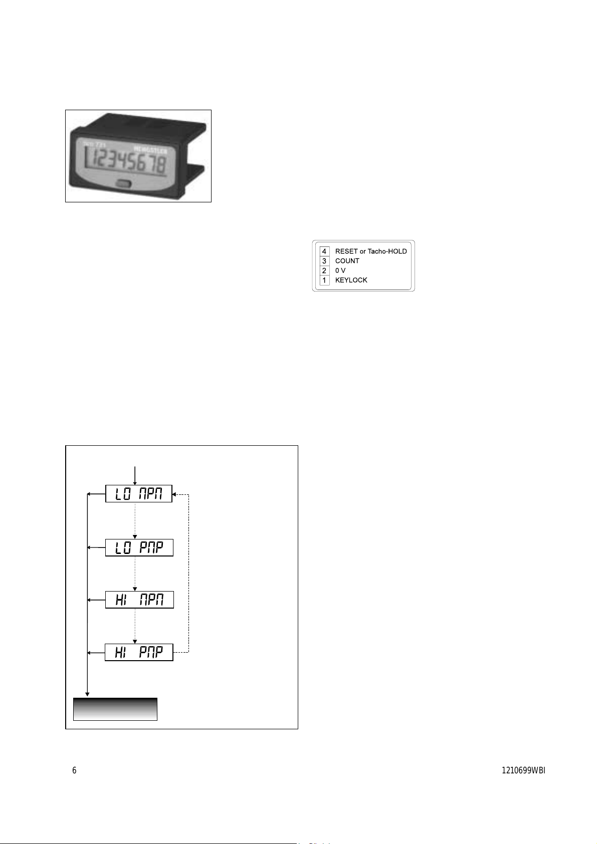
5. Klemmenbelegung
6. Technische Daten
Spannungsversorgung eingebaute Lithiumbatterie
Werterhaltung nominal 7 Jahre
Anzeige LCD, 8-stellig, 7 mm hoch
Zähleingang Klemme 3 „Count“
Zählflanke einstellbar: NPN: negativ (z.B.
potentialfreier Kontakt gegen 0V)
oder PNP: positives Spannungs-
signal; Impulsdauer min 70 µs
bzw. 15 ms (wenn auf 30 Hz
bedämpft)
Zählfrequenz einstellbar: „HI“ 7,5 kHz oder
„LO“ 30 Hz (bedämpft z. B. bei
prellenden Kontakten)
Amplitudenschwellen < 0,7 V und > 5 V, max 30 VDC
Rücksetzeingang Rücksetzen durch negative Flanke
an „RESET“, (Klemme 4 mit Brücke
zu 0V) Impulsdauer: min: 15 ms, da
prellsicher bedämpft auf 30 Hz
Tastrücksetzen kurzes Drücken der Fronttaste
Keylockeingang Sperre der Fronttaste durch eine
Brücke zwischen Klemme 2 und 1
Einbau Fronttafelmontage mit
Spannrahmenbefestigung
Frontabmessung DIN 48 mm x 24 mm
Einbauausschnitt 45 + 0,6 mm x 22 + 0,3 mm
Fronttafelstärke max. 14 mm
Einbautiefe 32 mm
Schutzart Frontseite IP 54
Betriebstemperatur -10° C bis +50°C
Lagertemperatur -20° C bis +60°C
Allgemeine Auslegung DIN EN 61010 Teil 1 bzw
VDE 0411 Teil 1
Schutzklasse entsprechend II
Überspannungskat. II
Verschmutzungsgrad 2
Betriebsanleitung tico 731.1
- Zähler mit Batterieversorgung
Der Zähler tico 731.1 ist ein Zähler für den Fronttafeleinbau mit
Batterieversorgung für Kontakt- oder Spannungsimpulse. Die
erhältlichen Ausführungen sind:
Standard Sonder
Summenzähler: 0 731 101 0 731 711
Tachometer (1/min): 0 731 102 0 731 712
Zeitzähler (Std:Min:Sec): 0 731 103 0 731 713
Zeitzähler (Std. 1/100 Std): 0 731 104 0 731 714
oder mit steckbaren Schraubklemmen z. Bsp. 0 731 101 S
Stromspar-Hinweis:
Der Zähler wird werksseitig im Stromsparmodus ausgeliefert. Das
Display zeigt „SLEEPING“. Durch kurzen Tastendruck wird der Zähler
aufgeweckt.
Hinweis: Der Stromsparmodus kann nicht reaktiviert werden.
1. Zähleingang programmieren
Zur optimalen Anpassung an Ihre Anwendung kann der Zähleingang
programmiert werden (prellsicher oder schnelles Zählen, positive oder
negative Impulsflanke).
Vereinfachung:
LO NPN ist bereits werksseitig voreingestellt (30 Hz und negative
Flanke).
Im Falle einer Umprogrammierung gehen Sie bitte folgendermaßen vor:
*
*
*
*
*
ZählmodusCount Mode
Zählmodus
Zählmodus
Wert bestätigen
lang drücken (> 2 sec)
*werksseitig voreingestellt
**entfällt bei Zeitzähler
Klemme 4 und 2 verbinden (Reset - 0 Volt)
und Fronttaste 8 sec gedrückt halten
Erläuterung:
Eingang prellsicher
bedämpft auf 30 Hz und
zählt auf die negative
Impulsflanke (z.B. Kontakte)
Erläuterung:
Eingang prellsicher
bedämpft auf 30 Hz und
zählt auf die positive
Impulsflanke (z.B. Kontakte)
Erläuterung:
zählt auf die negative
Impulsflanke bei max.
7,5 kHz Zählfrequenz
Erläuterung:
zählt auf die positve
Impulsflanke bei max.
7,5 kHz Zählfrequenz
kurz drücken
kurz drücken
kurz drücken
Einstellung ändern
1 230909 MD
7
2/6 Sach-Nr. 2 731 020; Version 1210699WBI
The tico 731.1 is a battery powered LCD-counter with programmable
count input for contact or edge triggering. The following versions are
available: standard special
Totalizer: 0 731 101 0 731 711
Tachometer (1/min): 0 731 102 0 731 712
Time counter (HHHH:MM:SS): 0 731 103 0 731 713
Time counter (HHHHHH.HH): 0 731 104 0 731 714
or with plug in screw terminal e. g. 0 731 101 S
Energy-save mode:
In order to save energy during delivery and stock, the counter is fac-
tory programmed to low-energy mode and the display shows
„SLEEPING“. To wake up the counter, just press the front button.
Remark: low energy mode cannot be reactivated.
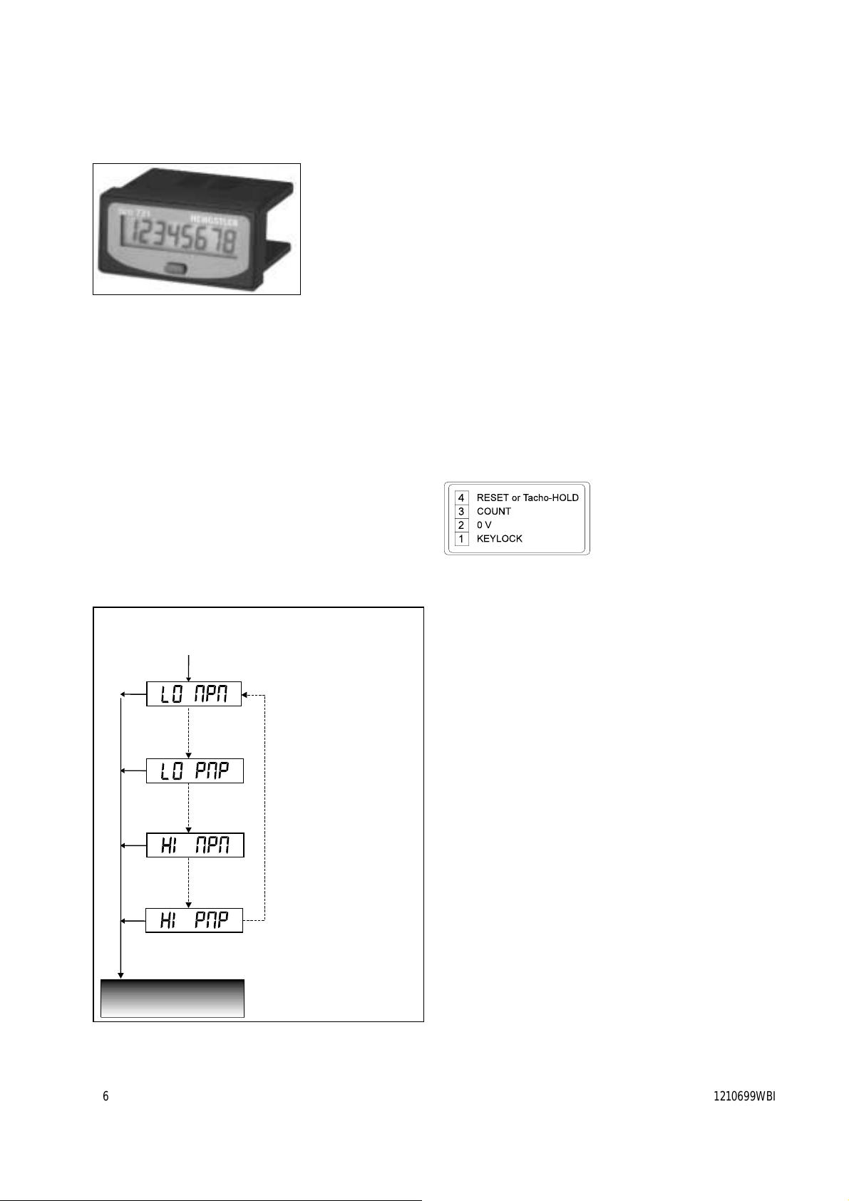
1. Programming of the COUNT-Input
In order to match your application, the COUNT-Input can be program-
med for high speed (7,5 kHz) or low speed counting (30 Hz attenua-
ted). Positive or negative edge is programmable as well.
NOTE:
The counter leaves the factory with the default value LO NPN
(fmax30 Hz and negative edge triggered).
To change the count input configuration:
2. Totalizer version (0 731 101)
Terminal 4 „RESET or Tacho-HOLD“ is defined as the Reset-Input.
3. Tachometer version (0 731 102)
The tachometer operates via the gate measuring method. Within the
measuring time of 6 sec, the incoming pulses are counted and recal-
culated in order to display 1/min.
The Terminal 4 „RESET or Tacho-HOLD“ is defined as the HOLD-Input
(as long as this Input is active, the actual value in the display is fro-
zen).
4. Time counters version (0 731 103 and 104)
The time counters will count as long as the Count-Input (3) is active.
(this can be a low or a high signal according to programming in
Chapter 1).
Terminal 4 „RESET or Tacho-HOLD“ is defined as the Reset-Input.
5. Terminal connection
6. Specifications
Power supply internal Lithium battery
Battery life nominal 7 years
Display LCD, 8-digit, 7 mm
Count input Terminal 3 „Count“
Active edge programmable: NPN: negative
(e.g. Contact to ground 0V) or
PNP: positive signal
pulse length: min 70µs or
min 15 ms (if attenuated to 30 Hz )
Count frequency programmable:
„HI“ 7,5 kHz or „LO“ 30 Hz (attenuated for
contacts)
Amplitude threshold < 0,7 V and > 5 V, max 30 VDC
Reset input Reset with a negative edge on „RESET“,
(Terminal 4 bridge to Ground, 0V)
pulse length: min 15 ms
(attenuated to 30 Hz )
Key reset press front key shortly
Keylock input Lock front key via bridge between terminals
2 and 1
Mounting Frontpanel mounted with clamping frame
Front dimension DIN 48 mm x 24 mm
Panel cut-out 45 + 0,6 mm x 22 + 0,3 mm
Panel thickness max. 14 mm
Product depth 32 mm
Protection class front side IP 54
Operating temperature -10° C to +50°C
Storage temperature -20° C to +60°C
General rating DIN EN 61010 part 1,VDE 0411 part 1
Protection class according to class II
Overvoltage category II
Contamination level 2
Operating instructions tico 731.1
- Battery powered LCD-Counter
*
*
*
*
*
press button longer (> 2 sec)
Note:
Maximum count speed
(7,5 kHz) and negative
edge triggered
Note:
Maximum count speed
(7,5 kHz) and positive
edge triggered
Note:
low count speed (30 Hz
attenuated) and negative
edge triggered (e.g.
contacts)
Note:
low count speed (30 Hz
attenuated) and positive
edge triggered (e.g.
contacts)
*default values
**not applicable to time counters
Connect Terminal 4 and 2 (Reset - 0 Volt)
and hold front button for 8 sec
press button shortly
to change values
press button shortly
to change values
press button shortly
to change values
toconfirm the desired value
ZählmodusCount Mode
Zählmodus
Count Mode
1 230909 MD
7

Sach-Nr. 2 731 020; Version 1210699WBI 3/6
2. Informazioni riguardo il totalizzatore (0 731 101)
Il morsetto d’ingresso 4 „RESET oppure Tacho-HOLD“ funziona come
ingresso di ripristino.
3. Informazioni riguardo il tachimetro (0 731 102)
Il tachimetro si basa sul principio di misurazione dei gate. Ciò significa
che entro il tempo di misurazione di 6 secondi vengono conteggiati gli
impulsi che arrivano e riconvertiti nell’unità 1/min. Il morsetto d’in-
gresso 4 „RESET oppure Tacho-HOLD“ funziona come ingresso-HOLD
(Blocco visualizzatore), ciò significa che fintanto che c’è un segnale
LOW (0 volt) all’ingresso, il valore sul display rimane bloccato.
4. Informazioni riguardo i contaore (0 731 103 e 104)
Il contaore conteggia il tempo, mentre all’ingresso di conteggio c’è
tensione. (secondo la programmazione nel Cap.1, è un livello alto
oppure basso).
Il morsetto d’ingresso 4 „RESET oppure Tacho-HOLD“ funziona come
ingresso di ripristino.
5. Morsettiera
6. Dati tecnici
Tensione di alimentazione Batterie al litio
Mantenimento dei valori nominale 7 anni
Display LCD, a 8 cifre, alto 7 mm
Ingresso di conteggio morsetto 3 „Count“
Fronte di conteggio programmabile: NPN: negativo
(contatto a 0V) oppure PNP: segnale di
tensione positivo; durata dell’impulso
min. 70 µs oppure 15 ms (smorzata a
30 Hz)
Frequenza di conteggio programmabile: „HI“ 7,5 kHz oppure
„LO“ 30 Hz (smorzata in caso di rim
balzi)
Soglie d’ampiezza < 0,7 V e > 5 V, massimo 30 V cc
Ingresso di ripristino il ripristino per mezzo del fronte
negativo su „RESET“, (morsetto 4 con
ponte a 0V) durata dell’impulso: min:
15 ms, libero da rimbalzi smorzato a
30 Hz
Ripristino a tasti premere brevemente il tasto frontale.
Blocco tasto frontale bloccasi il tasto frontale attraverso un
ponte dal morsetto 1 al morsetto 2
Montaggio pannello frontale con telaio di
fissaggio
Dimensione frontale DIN 48 mm x 24 mm
Dima foratura 45 +0,6 mm x 22 +0,3 mm
Spessore pannello frontale massimo 14 mm
Profondità prodotto 32 mm
Tipo di protezione lato frontale IP 54
Temperatura d’esercizio -10 C fino a +50 C
Temperatura di stoccaggio -20 C fino a 60 C
Criteri costruttivi DIN EN 61010 Parte 1 oppure VDE
0411 Parte 1
Classe di protezione secondo la classe II
Categoria di sovratensione II
Grado di contaminazione Grado 2
Istruzioni d’uso tico 731.1
- Contatore con alimentazione a batterie
Il contatore tico 731.1 è un contatore per il montaggio da pannello
frontale con alimentazione a batterie per impulso a contatto o a ten-
sione.
I modelli disponibili sono: standard special
Totalizzatore: 0 731 101 0 731 711
Tachimetro (1/min): 0 731 102 0 731 712
Contaore (Ora:Min:Sec): 0 731 103 0 731 713
Contaore (Ora 1/100 Ora): 0 731 104 0 731 714
appure con marsetti estraibili p. esempio 0 731 101 S
Modo di risparmio d’energia:
Dalla fabbrica il contatore viene programmato nel modo a risparmio
d’energia. Il display indica „SLEEPING“. Premendo brevemente il tasto il
contatore viene riattivato.
1. Programmazione ingresso di conteggio
Per rispondere in maniera ottimale alle vostre esigenze di utilizzo,
l’ingresso di conteggio può essere programmato (conteggio esente da
rimbalzi o conteggio veloce, fronte impulsi positivo o negativo).
Nota:
Il contatore viene programmato dalla fabbrica su fronte negativo NPN
(30 Hz).
Nel caso si voglia cambiare programma proseguire nel modo seguente:
*
*
*
*
*
Nota:
Nota:
conteggia fronte d’impulso
positivo ad una frequenza
massima di 7,5 kHz
Nota:
Nota:
**programmato dalla fabbrica
**non esiste nel contaore
Modo di conteggio
Unire morsetti 4 e 2 (Reset - 0 Volt)
e tenere premuto per 8 secondi il tasto frontale
Ingresso esente da rimbalzi
smorzato a 30 Hz e conteggia
il fronte d’impulso negativo
(per es. contatti)
Premere brevemente
per Cambiare i valori
ingresso esente da rimbalzi
smorzato a 30 Hz e conteggia
il fronte d’impulso positivo
(per es. contatti)
Premere brevemente
per cambiare i valori
conteggia fronte d’impulso
negativo ad una frequenza
massima di 7,5 kHz
Premere brevemente
per Cambiare i valori
Premere a lungo (> 2 sec)
per confermare i valori
1 230909 MD
7
4/6 Sach-Nr. 2 731 020; Version 1210699WBI
Remarques importantes:
- Une fois dans la configuration, la liaison de l’entrée „RESET“ à 0VCC
n’est plus nécessaire.
- C’est toujours l’état configuré précédemment qui apparaît en
premier.
Préservation de la capacité de la pile au stockage
Pour éviter une décharge de la pile pendant le stockage, le compteur
est mis en état de veille en sortie d’usine (affichage SLEEPING). Pour
réactiver le compteur, appuyer brièvement sur la touche en face
avant.
2. Fonction de l’entrée „RESET or Tacho HOLD“ en borne 4
Pour les versions compteur d’impulsions et compteur horaire, cette
entrée a pour fonction de remettre l’affichage à 0. Pour la version
tachymètre, elle permet de figer l’affichage tant qu’elle reste validée
par un niveau de tension négatif (0VCC).
3. Principe de fonctionnement du tachymètre
Le tachymètre totalise les impulsions reçues pendant un intervalle de
temps de 6 secondes.
Ce nombre d’impulsions est ensuite converti pour mettre à l’affichage
la valeur correspondant au nombre d’impulsions par minute.
4. Fonctionnement de la version compteur horaire
Le compteur enregistre la durée pendant laquelle l’entrée de compta-
ge reste validée par un niveau de tension positif ou négatif.
5. Raccordement électrique
6. Caractéristiques techniques
Alimentation interne par pile au lithium
durée de vie nominale 7 ans
Affichage LCD, 8 chiffres, de 7 mm
Entrée de comptage borne 3: „COUNT“
Résistance d’entrée environ 50 kOhm
Front actif configurable (voir synop.) :positif (PNP)
≥5VCC ou négatif (NPN) ≤0,7VCC
Largeur mini. de l’impulsion 70 µs ou 15 ms (si entrée bridée
à 30 Hz
Fréquence de comptage configurable (voir synoptique):
„HI“ 7,5 kHz ou „LO“ 30 Hz (bridée pour
éviter les rebonds dûs au contact)
Seuils de commande < 0,7 V und > 5 V, max 30 VDC
Entrée de remise à zéro borne 4: Front négatif ≤0,7VCC:
(RESET) ou mémoire Fréquence maxi.: 30 Hz; Largeur mini.
affichage (Tacho HOLD) de l’impulsion: 15 ms
Verrouillage de la touche actif: relier les bornes 1 et 2
Montage encastré avec collier de fixation
Dimensions face avant DIN 48 mm x 24 mm
Découpe encastrement 45 + 0,6 mm x 22 + 0,3 mm
Epaisseur paroi de fix. max. 14 mm
Profondeur 32 mm
Type de protection IP 54 face avant
Température de fonct. - 10°C à + 50°C
Température de stock. - 20°C à + 60°C
Conception générale DIN EN 61010 1ère partie ou VDE 0411
1ère partie
Classe de protection conformément à la classe II
Catégorie de surtension Catégorie II
Degré de salissure 2
Notice d’utilisation - tico 731.1
- Compteur avec alimentation par pile
Le compteur tico type 0 731.1 est prévu pour un montage encastré.Il
enregistre les impulsions fournies par un contact ou les impulsions
tension.
Il est disponible dans les versions suivantes:
standard spécial
Compteur d’impulsions 0 731 101 0 731 711
Tachymètre (1/mn) : 0 731 102 0 731 712
Compteur horaire (h : mn : s) : 0 731 103 0 731 713
Compteur horaire (h 1/100 h) : 0 731 104 0 731 714
ou bien avec barrier à vis débractable ex 0 731 101 S
1. Configuration de l’entrée de comptage COUNT en borne 3
Dans la majorité des cas d’utilisation, le compteur est commandé par
un contact libre de potentiel. Le compteur est donc livré avec une fré-
quence d’entrée bridée à 30 Hz pour éviter les conséquences des
rebonds de contact et avec commande par le 0VCC disponible en
borne 2. Ce qui correspond à un état de configuration LO NPN (voir
synoptique ce-dessous).
Dans ce cas, il n’ y a aucune intervention supplémentaire à exécuter. Si
un autre mode de fonctionnement de l’entrée est souhaité, il faut
procéder comme suit:
*
*
*
*
*
Zählmodus
Oui: appuyer >2 sec
sur touche
*Configuration usine
**Etat inexistant en version
compteur horaire
Non: appuyer
<1 sec sur
touche
Non: appuyer
<1 sec sur
touche
Non: appuyer
<1 sec sur
touche
Entrée de comptage NPN en
7,5 KHz (Impulsions tension
avec front actif négatif)
Entrée de comptage NPN bridée
à 30 Hz (Impulsions fournies par
un contact avec commande par
un front actif négatif)
Entrée de comptage PNP bridée
à 30 Hz (Impulsions fournies par
un contact avec commande par
un front actif positif)
Mettre l'entrée „RESET" or tacho „HOLD" (borne 4) à
0VCC (borne 2), puis maintenir la touche en face avant
enforcée pendant au moins 8 secondes
Entrée de comptage PNP en
7,5 kHz (Impulsions
tensions avec front actif
positif)
ZählmodusCount Mode
Zählmodus
Compteur prêt
à fonctionner
1 230909 MD
7
1 230909 MD
7


This manual suits for next models
1
Table of contents
Languages:
Other Hengstler Cash Counter manuals

Hengstler
Hengstler tico 772 User manual

Hengstler
Hengstler tico 731.2 User manual

Hengstler
Hengstler tico 731.4 User manual

Hengstler
Hengstler tico 731.2 User manual

Hengstler
Hengstler signo 723.1 User manual

Hengstler
Hengstler tico 732 User manual

Hengstler
Hengstler signo 723.1 Operating instructions

Hengstler
Hengstler tico 772 User manual

Hengstler
Hengstler Signo 721.2 User manual

Hengstler
Hengstler tico 731.3 User manual


