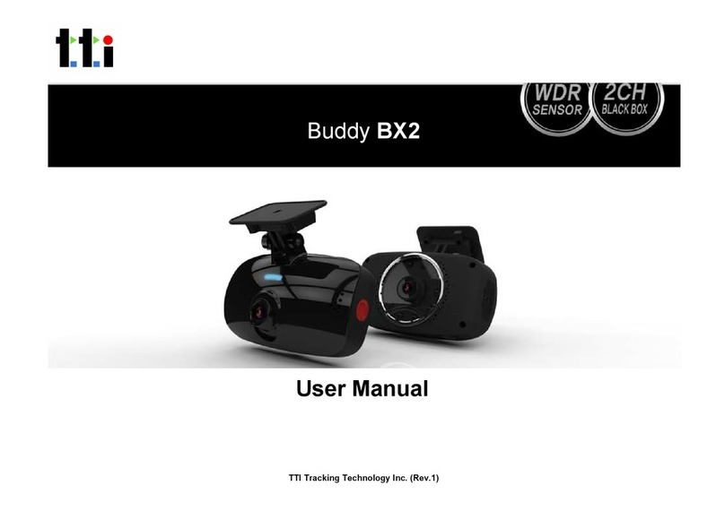
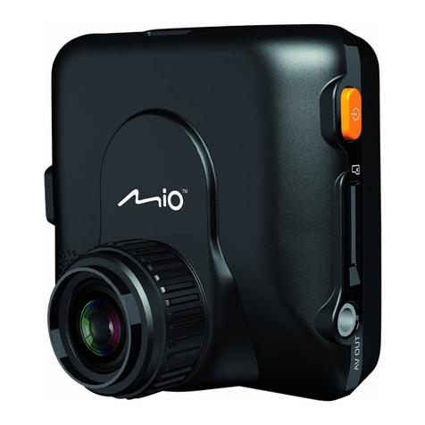
TTI SVC100GPS User manual

1
www.smartwitness.com
User Guide
VEHICLE JOURNEY RECORDER
Buddy BX1 with Cigarette Lighter (SVC100GPS)
Buddy BX1 Hardwired (SVC100GPS-LCA)
Buddy BX1 Hardwired with telematics (SVC100GPS-LCA2)
TTI Tracking Technology Inc.

www.tt-i.info
CONTENTS
GPS Function .............................................................................. 5
1. Overview ................................................................................ 6
SVC100GPS .................................................................. 7
SVC100GPS-LCA/-LCA2 ............................................... 8
SVC100GPS-LCA/-LCA2 - Wiring Description .............. 9
2. Contents ................................................................................ 10
3. Software Installation .............................................................. 11
4. SD Card Insert ....................................................................... 12
SD Card Care ................................................................ 15
5. Product Installation .............................................................. 16
SVC100GPS .................................................................. 16
SVC100GPS-LCA/-LCA2 .............................................. 16
6. LED Guide ............................................................................. 17
7. Camera Functions ................................................................ 18
Camera Operation ......................................................... 19
8. Software User Guide ............................................................ 20
PC Viewer Setting ......................................................... 20
File Loading ................................................................... 21
Playback Screen ........................................................... 23
Playback ....................................................................... 24
Google Maps ................................................................ 26
Thumbnail Function ...................................................... 27
Save JPG and AVI File ................................................. 28
Print Image ................................................................... 29
Reporting ...................................................................... 30
Backup Event/Log ........................................................ 31
Product Information ...................................................... 32
Log File Playback ......................................................... 33

CONTINUED...
GPS Log to KML Converter .............................................. 34
Enhanced Driver Report Function .................................... 35
9. Cloud Upload ........................................................................... 47
10. Setting the Journey Recorder ............................................. 48
Speed Dependant G-Sensor ........................................... 48
UserDenedG-Sensor................................................... 49
Auto Format Feature ....................................................... 50
Alarm Outputs ................................................................. 50
11. Specications ....................................................................... 52
Appendices
Appendix 1 - Recording Time Table ......................................... 53
Appendix 2 - Optional Accessory ............................................ 54
Appendix 3 - Firmware Upgrade .............................................. 57

4
SAFETY ADVICE
CAUTION
RISK OF ELECTRIC SHOCK
DO NOT OPEN
DO NOT REMOVE THE COVER
REFER SERVICING TO QUALIFIED SERVICE PERSONNEL
Connect your vehicle’s power cable (Cigarette Jack) to the
product after starting the vehicle to avoid damage.
Install the product where it does not block the driver’s view of
the road. Please refer to the installation section in the user
manual for a full guide on where to install product.
Damages caused by production malfunction, loss of data or
other damages that may occur while using this product is not
the responsibility of the manufacturer. When malfunction
occurs, the product may not save all videos and the sensor
may not recognise shock impacts.
WARNING:
DO NOT EXPOSE PRODUCT TO RAIN OR MOISTURE

5
1. Activate the product in an area without large buildings to improve
GPS reception.
For commercial purposes GPS has an average range error of more than 15
meters and the range error could be more than 100 meters depending on
environmental conditions like buildings and roadside trees etc.
2. The temperature range for optimum operation of the GPS receiver in
your car is -10 ~ 50°C.
3. When using the product for the rst time or after a long period (more
than three days), it may take a little longer to recognise your current
location.
ItmaytakebetweenveandthirtyminutestogetGPSreception.
1) If there is an object at the end of the GPS antenna
2) If your vehicle has metallic elements on the windshield
3) If equipment generating electromagnetic waves that interfere with the GPS
signal are installed in the vehicle e.g. other GPS devices including certain
types of wireless activated alarms, MP3 and CD players and camera
alarms using GPS.
4) If you are using a receiver connected by a cable, electrical interference can
be avoided by simply changing the location of the receiver (antenna).
5) On heavily overcast or cloudy days, if the vehicle is in a covered location
such as under a bridge or raised roadway, in a tunnel, an underground
roadway or parking area, inside a building or surrounded by high-rise
buildings.
6) If GPS signal reception is poor, it may take longer to locate your current
position when the vehicle is moving than when it is stationary.
GPS reception may be impaired under the following circumstances:
GPS RECEPTION

6
The SVC100GPS-LCA/-LCA2 is a Vehicle Journey/Accident Recorder with
3 Axis Shock Sensor & GPS for measuring braking, acceleration, driving
style and recording location. The unit includes a transparent locking case to
prevent tampering with evidence.
This evidence can protect a driver from many of the issues faced on the
roads today:
•Cash for Crash / Pre-meditated staged accidents
•False/Exaggerated Whiplash Claims
• ConictingReportsofActualEvents
•Lack of Witnesses
• DrivingOffenceAllegations(SpeedCameras,TrafcSignalViolations
etc...)
Features:
•Continuously records the driver’s view via a 170º high-quality lens
• Continuouslyrecordsbraking/acceleration/collisionG-forces
•Approved for installation in commercial vehicles
• Built-inGPSreceiverensuresthehighestaccuracyforvehicle
location and speed
• SimpleDIYinstallation
• E-mark,EMC,CEandFCCapprovedforextrapieceofmind
• VOSAandDataProtectionActcompliant
1. BUDDY - OVERVIEW

7
FRONT
Bracket
Stick adhesive
tape here
Camera Lens
SVC100GPS
RIGHT LEFT
DC Power In
(DC 12V~24V)
Memory
Card Slot
Internal GPS
Antenna
SD Card Format
Button
Record Button
Record LED
Blue LED
Overwrite LED
Red LED
REAR

8
FRONT
SVC100GPS-LCA/-LCA2
Bracket
Stick adhesive
tape here
Camera Lens
Tamper Resistant
Locking Case
RIGHT LEFT
Key Lock
Protects SD
Card Slot
DC Power Input
Connected with
permanent wiring
Rear
Internal GPS
Antenna
SD Card Format
Button
Record Button
Record LED
Blue LED
Overwrite LED
Red LED

9
SVC100GPS-LCA - Wiring Description
Remote SW+
Remote SW-
Battery -
Alarm Out (G-Sensor & Panic)
Battery+ (Connect to ignition)
For further information, please contact your installer.
If you want to power your camera permanently, please see Appendix 2 on
page 54.
SVC100GPS-LCA2 - Wiring Description
Remote SW+
Remote SW-
Battery -
Alarm Out (G-Sensor & Panic)
Battery+ (Connect to ignition)
Alarm Out (SD Card Fault)

10
2. CONTENTS
SVC100GPS Camera
/Recording Unit including bracket
Wire Splice Clips
Sticker for Windscreen
Mounting (Double-sided Tape x 2)
Power Cable (Cigarette Jack)
Spare Mounting Bracket
USB 2.0 SD Card Reader
Spare Mounting Bracket
SD Memory Card*
*SD Card size will depend on the
model and may not be included.
SVC100GPS SVC100GPS-LCA/-LCA2
Item contains all accessories on
the left, plus the following:
Keys for Locking Case
Transparent Locking Case
Telematics Cable
Please note: The SVC100GPS-
LCA2 will have an extra alarm
output wire

11
3. SOFTWARE INSTALLATION
Software Installation (Windows)
PC SYSTEM REQUIREMENT
RecommendedPCspecicationsforPCViewersoftware
If the PC does not meet the minimum system requirements, the Analysis
Software may not function properly.
OS Windows 2000, Windows XP, Windows Vista,
Windows 7
CPU Pentium4 2.6GHZ or higher
RAM 512MB or higher
Interface SD Memory Card Reader
HDD Free Space Install 20MB or higher
Backup 2GB or higher
Display 1,024 x 768 pixel / High Colour (16 bit) or higher
Software Installation (Windows) The Buddy BX1 software is called
SMARTWITNESS

12
1. To download the SVC100GPS software, type ‘www.smartwitness.com’
into your browser and go to the support section.
2. Choose ‘Software’ and ‘SVC100GPS’ options from the drop down
menu as shown below.
3. Clickthe‘Download’button(lewillautomaticallydownloadtoPC).
4. When downloaded, go to the ‘Downloads’ folder and double click the
‘Setup’le.
5. Select the language and then follow the on screen dialog box.
6. The ‘PCViewer’ icon will now be displayed on your desktop.
*Screenshot taken from www.smartwitnes.com
NOTE: To Un-install the PC Viewer
Open the ‘Control Panel’
Select ‘Remove Program’ and remove PC Viewer SVC100GPS

13
4. SD CARD INSERT
If you have been supplied with an SD card, then
this will need to be setup using the latest Smart
Witness Software.
PLEASE NOTE
1. Insert the SD memory card into the computer using the SD card reader.
2. This software can be downloaded from
www.tt-i.info/support
3. Once on the page, select the correct software by using the Drop Down
Menu
4. When downloaded, go to the ‘Downloads’ folder and double click the
‘setup’le.
5. Follow the setup - instructions, then the software icon will appear on your
desktop.
6. Double click the software icon to load the software. (Below)

14
7. Click the ‘Tool’ button
8. Select the “SD Card Initilize” button from the drop down menu
9. You will be presented with another drop down list to select the card to
format.
10. Select the “DRIVERREC” from the drop
down and tick the “Quick Format” box
when prompted.
11. Click “Start” to begin formatting.
12. Once the card has been formatted, you
will see the screen on the right.
Then, remove the SD Card from the
computer.
13. Make sure the unit is turned off before
inserting the SD Card.
14. Insert the SD memory card into the SD
card slot.
TheveryrsttimeyoupowerupyourunitwiththeSDCardinserted,itis
important not to disconnect the power before the 2 minutes are up, as this
may damage the unit.
PLEASE NOTE

15
SD CARD CARE
SD cards are a popular recording consumable. They are very robust and
reliable.
However, if they are not correctly maintained their lifespan can be reduced
andthelestructurecouldbecomecorrupt.MaintainingSDcardsisquick
and easy and is carried out by regular formatting.
If you ever experience card failure, missing or corrupt recordings, then this is
a sign that the SD card is in need of a format. All makes and models of Micro
SD and full size SD cards require formatting regularly.
AUTO FORMAT FEATURE
The Smart Witness SVC100GPS range has a convenient feature that will
Auto Format the SD card if it detects a card error. The process takes less
than 10 seconds and will delete all data on the card. For this reason we
advise you to immediately remove the card from the unit and take a backup
of an incident that needs to be kept has occurred.
For full details on how to use this feature, please refer to section 10
CARD FAILURE INDICATOR
IftheAutoFormatfeaturecannotxthecardissuethecardmaybefaulty.In
this case both LEDs on the unit will be solid for over 20 seconds,
indicating a card fault. The card should then be checked for errors using a
computer. If the card cannot be repaired or formatted by a computer it is
likely that the card will need to be replaced.
Under no circumstances whatsoever shall Smart Witness be liable for any
indirectorconsequentiallossorforanylossofprots,lossofbusiness,
depletion of goodwill, loss of data, loss of opportunity, loss of
contract and any similar loss arising from the purchase and use of this
product.
PLEASE NOTE

16
5. PRODUCT INSTALLATION
SVC100GPS - DIY Fitting
1. Attach the double sided adhesive
tape to the unit.
2. Secure the SVC100GPS to the
windscreen behind the rear view
mirror. Please make sure that the
surface is clean and dry before
attaching.
Tip:
Hold in position
withrm
pressure for
30 Seconds
3. Adjust camera view and make
sure the lens has an unobstructed
view.
4. Arrange the power cord neatly
alongside the windshield and
door pillar trim. Use the provided
wire splice clip.
5. Connect the SVC100GPS to the cigarette
lighter socket.
SVC100GPS-LCA-LCA2 - Professional Installation Recommended
Please don’t attempt to permanently wire this unit
unless you are familiar with auto wiring.
Any incorrect installations will not be covered by
the warranty. For a full wiring description,
please see section 2.1.

17
- Professional Installation Recommended
6. LED GUIDE
Blue LED
Red LED
See the table below for an explanation of the LED status changes on the
back of the recorder.
No. BLUE LED RED LED Meaning
1Blink every half second OFF Event Recording
2Blink every 4 seconds OFF Continuous Recording
3Solid OFF Pre-Recording
(Awaiting Triggers)
4OFF Blink every half second Card Fault
5SOLID SOLID System Booting Up
6Blink every half second Blink every half second Unit Fault
7SOLID OFF SD Card Removal
in Safe Mode
8OFF OFF No Power

18
7. CAMERA FUNCTIONS
Connect your vehicle’s power cable to the SVC100GPS after starting the
vehicle and the SVC100GPS will automatically start.
(Use the provided power cable.)
Auto Start Function
PLEASE NOTE
The unit will not start recording immediately after power on. It takes around 1
minute for the built-in power backup system to charge. Thereafter, the
internalashmemorywillbereadytorecord.
Event Recording
The event recording will be automatically started by the G-sensor.
The G-sensor sensitivity can be set by your PC. To set the G-Sesnor
Sensitivty, please refer to section 10 - Setting the Vehicle Journey
Recorder.Eacheventlecontains15secondsprior&5secondspostevent.
Manual Recording
Pressthe[RECORD]buttontobeginrecordingmanually.Eachmanualle
contains 15 seconds prior to activation & 5 seconds post activation.
Continuous Recording
The continuous recording will be automatically started after the unit is turned
on.TheSVC100GPSdoesn’tmakeaseparateeventleduringthe
continuous recording. It will mark the Event area by the G-sensor or Record
buttoninthecontinuousrecordinglewhichcanbeeasilysearchedfor
during playback.
Built-in power backup (Super Capacitor)
Whenpowertotheunitisinterrupted,theSVC100GPScreatesthelastle
using the internal Super Capacitor. This will ensure that no vital information
is lost during that time.
Buzzer
A ‘Beep’ sound will occur when recording starts (this can be turned off if
required).
Camera Operation

19
1. Connect your vehicle’s power cable to the SVC100GPS after starting the
vehicle.
2. Blue LED & Red LED will be slowly blinking simultaneously and then the
Blue LED will remain on. The Blue LED light means SVC100GPS is
ready for the event recording.
3. The event recording will automatically begin by the G-sensor with one
short “Beep” sound.
4. The manual recording will start by pressing the [RECORD] button.
Multiple impacts coverage
Flash memory captures the video data from the second impact even as the
rstimpactisstilloccurring.Itwillstartwritingimmediatelyaftertherst
recordingisnished.
Normal Record
1. Connect your vehicle’s power cable to the SVC100GPS after starting
the vehicle.
2. Blue LED & Red LED will be slowly blinking simultaneously and then the
BlueLEDwillremainonandashevery4seconds.
3. BlueLEDlightashingevery4secondsmeansSVC100GPSis
recording continuously.
4. The continuous recording (normal recording) will automatically begin just
after the power is turned on.
Event Record
PLEASE NOTE
Camera Operation

20
This setting is for the PC Viewer itself. To set the Recorder, refer to
Section 10.
The ‘Date’ formats and ‘Speed’ unit will be set automatically according to the
PC Windows settings, however it can be changed with this PC viewer setting
menu:
Normal Video
Left/Right Flip
Up/Down Flip
PC Viewer Setting
8. SOFTWARE USER GUIDE
File Loading
This manual suits for next models
3
Table of contents
Other TTI Dashcam manuals

