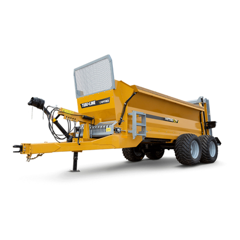
Tube-Line NITRO 275RS User manual

44996
Operator’s Manual
Keep this manual with the machine at all times.
Manure Spreader
Nitro
PRINTED IN CANADA
Tubeline Manufacturing Limited
6455 Reid Woods Drive RR #4
Elmira, Ontario, Canada N3B 2Z3
Email:
Fax: 519.669.5808
Tel: 519.669.9488
Toll-free (North America): 1.888.856.6613
www.tubeline.ca
Do not attempt to operate this machine without thoroughly
reviewing this manual for safe and proper operation.
Rev. 1-0

Nitro -
Operator’s Manual
I
Operator’s Manual
Thank you for choosing a Tubeline Manure Spreader. Our hope is that it will give you many years of productive
service. This machine is designed to spread various types of manure evenly over a wide area.
Please read and understand this manual and the machine before operation.
Warranty and Limitation of Liability
All equipment is sold subject to mutual agreement that it is warranted by the company to be free from defects
of materials and workmanship. But the company shall not be liable for special, indirect or consequential,
damages of any kind under this contract or otherwise. The company’s liability shall be limited exclusively to
replacing or repairing without charge, at its factory or elsewhere, at its discretion.
Any material, or workmanship defects which become apparent within one year from the date on which the
equipment was purchased, and the company shall have no liability for damages of any kind. The buyer by the
acceptance of the equipment will assume all liability for any damages, which may result from the use or misuse
by his employees or others.
Nitro Apron Chain Warranty
Tubeline Manufacturing Ltd offers a limited lifetime non-transferable warranty to the original purchaser of
a Nitro manure spreader. This warranty applies to chain link breakage and covers parts only. Should a
connecting link fail, only it will be replaced. However, if a standard link breaks the complete chain will be
provided. Freight and labor to install is the responsibility of the purchaser and is not covered under the terms of
the limited warranty.
Warranty coverage is null and void unless Warranty Registration form has been completely lled in and is on
le at Tubeline Manufacturing Ltd.
Manuals
Parts manuals are printed and shipped with machines as they leave the manufacturer. Your machine may
include parts or features not yet included in the initially shipped manual. The latest manual version can be
found at
www.tubeline.ca/support
. Tubeline reserves the right to update and change manuals as seen t.
Dealers are informed of any pressing changes/ modications. They can help you with any questions regarding
replacement parts.
Serial Number
The implement serial number is located on the front of the frame. This number helps us to track changes and
improvements and must be mentioned when ordering parts or requesting service. For your convenience, a
space has been provided inside the front cover of this manual to record the serial number, model number,
purchase date, and dealer name.
Model No: _______________________________________
Serial No: ________________________________________
Date Purchased: __________________________________
Dealer Name: ____________________________________

II Table of Contents - Nitro
Table of Contents
Operator’s Manual I
Warranty and Limitation of Liability ............................................................I
Nitro Apron Chain Warranty..................................................................I
Manuals.................................................................................I
Serial Number ............................................................................I
Principals of Operation ....................................................................IV
Intended Use ............................................................................IV
Section 1 - Specications 1-1
Terminology ............................................................................1-4
Hydraulic Requirements ..................................................................1-5
PTO / Horsepower Requirements ...........................................................1-5
Tire Load Index Charts ...................................................................1-5
425/65 R22.5 Recap Truck ................................................................1-5
480/70 R30 R-1W .......................................................................1-5
550/45-22.5 I-3 .........................................................................1-5
600/65R34 R-1W........................................................................1-6
700/50-26.5 I-3 .........................................................................1-6
710/50R26.5 CargoXBIB 170D TL HF. . . . . . . . . . . . . . . . . . . . . . . . . . . . . . . . . . . . . . . . . . . . . . . . . . . . . . . .1-7
710/70R38 R-1W........................................................................1-8
710/70R38 R-1W VF .....................................................................1-8
710/70R42 R-1W........................................................................1-9
Section 2 - Safety 2-1
Safety Symbol ..........................................................................2-1
Safety Signal Words .....................................................................2-1
General Safety. . . . . . . . . . . . . . . . . . . . . . . . . . . . . . . . . . . . . . . . . . . . . . . . . . . . . . . . . . . . . . . . . . . . . . . . . .2-1
Personal Protection Equipment (PPE) .......................................................2-2
Operation Safety ........................................................................2-2
Tire Safety .............................................................................2-3
Hydraulic Safety ........................................................................2-3
Maintenance Safety......................................................................2-4
Lighting & Clearance Marking ..............................................................2-5
Safety Signs ...........................................................................2-5
Installing Safety Signs ....................................................................2-6
Safety Sign Locations ....................................................................2-6
Safety Decals ..........................................................................2-7
ISO Safety Decal Locations. . . . . . . . . . . . . . . . . . . . . . . . . . . . . . . . . . . . . . . . . . . . . . . . . . . . . . . . . . . . . . . .2-8
ISO Safety Decals .......................................................................2-9
Section 3 - Operation 3-1
Tractor Preparation ......................................................................3-1
Spreader Preparation ....................................................................3-1
Hook-up / Unhooking.....................................................................3-2
Loading ...............................................................................3-3
Spreading .............................................................................3-3
Unplugging ............................................................................3-3
Reversing Apron Chain ...................................................................3-4
After operating for 2 hours: ................................................................3-4
After operating for 10 hours: ...............................................................3-4

Nitro - Table of Contents III
Optional Hydraulic Brake Operation .........................................................3-4
Optional Flow Control Operation ............................................................3-4
Optional Night Light Kit Operation...........................................................3-5
Optional Two Stage Beater Operation........................................................3-5
Optional Scale System ...................................................................3-5
Section 4 - Transportation / Storage 4-1
Transport Safety ........................................................................4-1
Storage Safety..........................................................................4-1
Travel Speed ...........................................................................4-1
Storage and Cleaning ....................................................................4-1
Section 5 - Service & Maintenance 5-1
Apron Chain Tension Adjustment ...........................................................5-1
Wheel Torque Specications ...............................................................5-1
Optional Two Stage Beater Paddle Adjustment.................................................5-2
Optional Two Stage Beater Endgate Adjustment ...............................................5-2
Fluids & Lubricants ......................................................................5-3
Greasing your Machine ...................................................................5-3
Grease Points ..........................................................................5-4
Optional Grease Line Ports ................................................................5-6
Optional Two Stage Beater Lubrication Points .................................................5-8
Optional Two Stage Beater Lubrication Points (750 - 950) ........................................5-9
Torque Values - Imperial V
Torque Values - Metric VI

IV
Operator’s Manual
- Nitro
Principals of Operation
The Nitro Manure Spreader is designed to be hitched behind a tractor. The Manure Spreader consists of a poly
board oor trailer with an apron chain drag system, that pulls material to the rear of the trailer, through a set of
vertical, spinning beaters and is then spread in an even pattern on the eld. The rear beaters are connected
to the tractor’s PTO via gearboxes and PTO drivelines. The variable speed apron chain is operated from the
tractor cab, and controls the speed of materials being fed through the beaters.
The apron chain and rear lift gate are operated using the tractor’s hydraulic power outputs. The rear lift gate
prevents material from jamming the beaters while loading, as well as preventing material from falling onto a
roadway during transport.
We recommend that you carefully read this entire manual before operating the Manure Spreader. Please do
not assume you know how to operate and maintain your machine before reading this manual carefully. Keep
this manual available for reference.
Call your authorized dealer if you need any assistance or more information.
Intended Use
The Nitro manure spreader is well suited to apply most forms of manure to elds as a fertilizing method. It is
less commonly used to spread compost, lime, wood ash and seaweed fertilizer. The removal of the rear vertical
beaters also allows the Nitro spreader to be used as a pit trailer for forage materials. An optional two stage
beater kit is recommended for chicken litter and other similar materials.

Nitro -
Section 1 - Specications
1-1
Section 1 - Specications
NITRO 275RS
Cu.ft. Struck 220’ Overall Length 23.5’
Heaped Cu.ft 290’ Beater Diameter 34”
Inside Width 62” Beater Speed 420 RPM
Inside Depth 32” Axle Type Single/Tandem
Inside Length 160” Hub Capacity 16,000/12,000 lbs
Loading Height 69” PTO Speed 1000 RPM
NITRO 375RS
Cu.ft. Struck 281’ Overall Length 25’
Heaped Cu.ft 410’ Beater Diameter 34”
Inside Width 62.5” Beater Speed 420 RPM
Inside Depth 34.5” Axle Type Tandem
Inside Length 175” Hub Capacity 12,000 lbs
Loading Height 74” PTO Speed 1000 RPM
* Weight on tires will affect spreader height *

1-2
Section 1 - Specications
- Nitro
NITRO 450
Cu.ft. Struck 316’ Inside Depth 40” Overall Length 27’ Axle Type Single/Tandem
Heaped Cu.ft 453’ Inside Length 201” Beater Diameter 34” Hub Capacity 12,000 lbs
Inside Width 62” Loading Height 77” Beater Speed 420 RPM PTO Speed 1000 RPM
NITRO 525RS
Cu.ft. Struck 407’ Inside Depth 45.5” Overall Length 27.5’ Axle Type Tandem
Heaped Cu.ft 555’ Inside Length 218” Beater Diameter 34” Hub Capacity 12,000 lbs
Inside Width 62.5” Loading Height 80” Beater Speed 420 RPM PTO Speed 1000 RPM
* Weight on tires will affect spreader height *

Nitro -
Section 1 - Specications
1-3
NITRO 600
Cu.ft. Struck 436’ Inside Depth 50” Overall Length 29.5’ Axle Type Single/Tandem
Heaped Cu.ft 593’ Inside Length 227” Beater Diameter 34” Hub Capacity 16/20,000 lbs
Inside Width 62” Loading Height 90” Beater Speed 420 RPM PTO Speed 1000 RPM
NITRO 750
Cu.ft. Struck 602’ Inside Depth 58” Overall Length 32.5’ Axle Type Single/Tandem
Heaped Cu.ft 791’ Inside Length 252” Beater Diameter 36” Hub Capacity 16/20,000 lbs
Inside Width 67” Loading Height 100” Beater Speed 420 RPM PTO Speed 1000 RPM
* Weight on tires will affect spreader height *

1-4
Section 1 - Specications
- Nitro
NITRO 950
Cu.ft. Struck 740’ Overall Length 35.25’
Heaped Cu.ft 950’ Beater Diameter 36”
Inside Width 67” Beater Speed 420 RPM
Inside Depth 58” Axle Type Tandem
Inside Length 297” Hub Capacity 20,000 lbs
Loading Height 102” PTO Speed 1000 RPM
* Weight on tires will affect spreader height *
Terminology

Nitro -
Section 1 - Specications
1-5
Hydraulic Requirements
The Nitro Manure Spreader requires 16 GPM hydraulic ow for optimal performance.
PTO / Horsepower Requirements
NITRO HORSEPOWER REQUIREMENTS
Model HP Required
275RS 80hp
375RS 90hp
525RS 125hp
450 125hp
600 150hp
750 150hp
950 200hp
Tire Load Index Charts
Replacement tires must match or exceed the specications in that size tire’s chart.
480/70 R30 R-1W
Tire Size TT/TL Rim Unloaded Static Load
Radius
Rolling
Circumf
Load / Speed
Index
Max
Pressure
Max Load
OD SW
480/70 R30 TL 15in 59.7 in 19 in 27 in 177 in 152B 46 psi 7850 lbs
425/65 R22.5 Recap Truck
Tire Size Load
Range
Weight Rim Unloaded Loaded Static
Loaded
Radius
Revs
per
mile/
km
Max
Pressure
Max Load Max
Speed
OD SW Width
425/65
R22.5
L 192 lbs/
87 kg
12.25in 59.7 in/
1140
mm
16.1 in/
409 mm
17.8in/
452 mm
20.8 in/
528 mm
463
mile/
288 km
120 psi/
830 kPa
11400 lbs/
5170 kg
65mph/
104
kmh
550/45-22.5 I-3
Tire
Size
TT/
TL Rim
Unloaded Loaded
Static
Radius
Rolling
Circumf
Load / Speed
Index (16 PR) Pressure
psi (bar)
Recommended Load lbs (kg)
Drive Wheel Free Rolling
SW OD DW FR
6 mph
(10
km/h)
16mph
(25
km/h)
25 mph
(40
km/h)
31mph
(50
km/h)
6 mph
(10
km/h)
16mph
(25
km/h)
25 mph
(40
km/h)
31mph
(50
km/h)
550/45
-22.5 TL 16DC
18DC
27.6in/
550
mm
52.5in/
1070
mm
22.8in/
470
mm
155.4in/
3175
mm
147A8 159A8
12 (.8) 4560
(2070)
3880
(1760)
3260
(1480)
2940
(1332)
6500
(2950)
5530
(2510)
4650
(2110)
4190
(1900)
17 (1.2) 5800
(2630)
4940
(2240)
4150
(1880)
3730
(1692)
8250
(3740)
7010
(3180)
5890
(2670)
5290
(2400)
29 (2) 7800
(3540)
6640
(3010)
5580
(2530)
5020
(2277)
11110
(5040)
9440
(4280)
7940
(3600)
7140
(3240)
35 (2.4) 8660
(3930)
7360
(3340)
6200
(2810)
5580
(2529)
12350
(5600)
10490
(4760)
8820
(4000)
7940
(3600)
41 (2.8) 9500
(4310)
8070
(3660)
6780
(3075)
6100
(2768)
13510
(6130)
11490
(5210)
9650
(4375)
8690
(3940)

1-6
Section 1 - Specications
- Nitro
600/65R34 R-1W
Tire
Size TT/TL Rim
Unloaded Static
Load
Radius
Rolling
Circumf
Load /
Speed
Index
Pressure
(kpa)
Load Capacity (kg) Tread
Depth
OD SW Static 10
km/h
25
km/h
30
km/h
40
km/h
50
km/h
60
km/h
600/65
R34 TL 18” 1665
mm
607
mm 750 mm 4992
mm
151D/
154A8
140 7935 5175 3830 3690 3450 3450 3140
49 mm
160 8625 5625 4160 4010 3750 3750 3450
157D/
160A8
200 9210 6010 4445 4285 4005 4005 3645
240 10350 6750 4995 4815 4500 4500 4125
700/50-26.5 I-3
Tire
Size
TT/
TL Rim
Unloaded Loaded
Static
Radius
Rolling
Circumf
Load / Speed
Index (16 PR) Pressure
psi (bar)
Recommended Load lbs (kg)
Drive Wheel Free Rolling
SW OD DW FR
6 mph
(10
km/h)
16mph
(25
km/h)
25 mph
(40
km/h)
31mph
(50
km/h)
6 mph
(10
km/h)
16mph
(25
km/h)
25 mph
(40
km/h)
31mph
(50
km/h)
700/50
-26.5 TL 24DC
27.6in/
700
mm
52.5in/
1333
mm
22.8in/
580
mm
155.4in/
3948
mm
162A8/
158B
174A8/
170B
29 (2) 13180
(5980)
11200
(5080)
9410
(4270)
8470
(3840)
18590
(8430)
15790
(7160)
13270
(6020)
11950
(5420)
32 (2.2) 13910
(6310)
11840
(5370)
9940
(4510)
8950
(4060)
19670
(8920)
16710
(7580)
14040
(6370)
12630
(5730)
35 (2.4) 14660
(6650)
12460
(5650)
10470
(4750)
9440
(4280)
20680
(9380)
17570
(7970)
14770
(6700)
13290
(6030)
48 (3.3) 20970
(9510)
17810
(8080)
14970
(6790)
13490
(6120)
24820
(11260)
21080
(9560)
17730
(8040)
15960
(7240)
Highlighted row indicates cyclic high load variations. 1) When tire equip vehicles subject to haulage cyclic high load variations excluding
transport applications on long distances, i.e. vehicles used on round trips (e.g. from eld to farm) where on one way the vehicle is
empty and on the other way the gross vehicle mass exceeds two times the mass of empty vehicle (last two rows in the table). 2) When
tted on tractor steering wheels load capacities are 80% of free rolling and ination pressure 20% higher. 3) For 10km/h and stationary
use ination pressure raised 20% and 25%. 4) Load for intermediate speed should be taken as an average between two close speeds.
5) Load at lower speed than 10km/h may be similar to the load for 10km/h.

Nitro -
Section 1 - Specications
1-7
MSPN: 29880 CAI: 892516
Load Per Tire (single) - lbs (kg)
Pressure psi/ bar 6mph/ 10 kmh 15mph/ 25 kmh 25mph/ 40 kmh 30mph/ 50 kmh 40mph/ 65 kmh
12/ .8 7740 (3510) 6790 (3080) 5840 (2650) 5200 (2360) 4300 (1950)
17/ 1.2 12020 (5450) 10240 (4645) 8910 (4040) 7900 (3585) 6590 (2990)
23/ 1.5 14440 (6550) 12470 (5655) 10790 (4895) 9590 (4350) 7970 (3615)
29/ 2 16870 (7650) 14680 (6660) 12690 (5755) 11280 (5115) 9340 (4235)
35/ 2.4 19290 (8750) 16910 (7670) 14570 (6610) 12960 (5880) 10710 (4860)
41/ 2.8 20410 (9260) 17900 (8120) 15430 (7000) 13720 (6225) 11340 (5145)
46/ 3.2 21550 (9775) 18900 (8575) 16280 (7385) 14480 (6915) 11970 (5430)
52/ 3.6 22690(10290) 19910 (9030) 17130 (7770) 15240 (6915) 12600 (5715)
55/ 3.8 23250 (10545) 20400 (9255) 17560 (7965) 15630 (7090) 12920 (5860)
58/ 4 23810 (10800) 20900 (9480) 17990 (8160) 16010 (7260) 13230 (6000)
*All load values are for maximum indicated speeds at low torque.
*20 mph (30km/h): High torque eld work or max road speed.
*All Load values for ground slopes up to 20% (above 20% consult Michelin).
Tire Technical Data
Unloaded Dimensions Loaded Dimensions Rims (preferred in bold)
Overall Width Overall Diameter Loaded Radius Rolling Circum AG24.00(H2) AG20.00
(H2)
28.6in/ 726 mm 54.3in/ 1380 mm 23.4in/ 594 mm 159.9in/ 4061 mm
Gross Flate Plate Tire Weight 100% Tire Volume Centerline Tread
Depth Min Dual/ Triple Spacing
406 sq in/ 2619 sq cm 375lbs/ 170 kg 143.4 gals/ 543 lt 23/32nds/ 922 mm 36.6in/ 922 mm
Rolling Circum Index Number of Lugs
0 0 x 2
710/50R26.5 CargoXBIB 170D TL HF

1-8
Section 1 - Specications
- Nitro
710/70R38 R-1W VF
Highlighted column indicates speed limit 25km/h to 65 km/h.
Tire
Size TT/TL Rim
Unloaded Static
Load
Radius
Rolling
Circumf
Load /
Speed
Index
Pressure
psi (bar)
Load Capacity lbs (kg) Mixed Application
SW OD Static 6 mph
(10 km/h)
16mph
(25 km/h)
19mph
(30 km/h)
25 mph
(40 km/h)
31mph
(50 km/h)
710/70
R38 TL DW23B
29.2/ 76.8 34.0/ 229.8in/ 166A8/
166B
19 (1.3) 23700
(10790)
15510
(7040)
11480
(5210)
11060
(4690)
10330
(4690)
9410
(4270)
22 (1.5) 25840
(11730)
16850
(7650)
12470
(5660)
12030
(5460)
11230
(5100)
10220
(4640)
23 (1.6) 26850
(12190)
17510
(7950)
12950
(5880)
12490
(5670)
11670
(5300)
10620
(4820)
28.2in/
1958
mm
77.1in/
716
mm
34.6in/
880
mm
227.1in/
5768
mm
172A8/
172B
17 (1.2) 21300
(9660)
13890
(6300)
10270
(4660)
9900
(4490)
9260
(4200)
9260
(4200)
23 (1.6) 25200
(11430)
16450
(7460)
12170
(5520)
11730
(5320)
10960
(4970)
10960
(4970)
29 (2) 28700
(13020)
18720
(8490)
13850
(6280)
13360
(6060)
12480
(5660)
12480
(5660)
35 (2.4) 31950
(14490)
20830
(9450)
15410
(6990)
14860
(6740)
13890
(6300)
13890
(6300)
28.2in/
1958
mm
77.1in/
716
mm
35.5in/
902
mm
222.2in/
5645
mm
178A8/
178B
15 (1) 18560
(8420)
12100
(5490)
8950
(4060)
8640
(3920)
8070
(3660)
17 (1.2) 20640
(9360)
13470
(6110)
9970
(4520)
9590
(4350)
8970
(4070)
22 (1.5) 23520
(10670)
15340
(6960)
11350
(5150)
10940
(4960)
10230
(4640)
29 (2) 27840
(12630)
18170
(8240)
13430
(6090)
12940
(5870)
12100
(5490)
36 (2.5) 31750
(14400)
20700
(9390)
15320
(6950)
14770
(6700)
13800
(6260)
44 (3) 35340
(16030)
23060
(10460)
17060
(7740)
16450
(7460)
15370
(6970)
49 (3.4) 38030
(17250)
24800
(11250)
18360
(8330)
17700
(8030)
16540
(7500)
Tire
Size TT/TL Rim
Unloaded
Static
Load
Radius
Rolling
Circumf
Load /
Speed
Index
Pressure
psi (bar)
Recommended Load lbs (kg)
SW OD
CFO No high and sustained torque, road
transport
9 mph
(15
km/h)
19mph
(30
km/h)
6 mph
(10
km/h)
9 mph
(15
km/h)
12
mph
(20
km/h)
40
mph
(65
km/h)
43
mph
(70
km/h)
VF
710/70
R38
CFO
TL
DW23B
DW24B
DW25B
28.3in/
1959
mm
77.1in/
720
mm
33.2in/
843
mm
225.1in/
5717
mm
178D
12 (.8) 13870
(6291)
11570
(5250)
11180
(5070)
10430
(4730)
10430
(4730)
10430
(4730)
9480
(4300)
15 (1) 15860
(7195)
13240
(6005)
12790
(5800)
12790
(5410)
12790
(5410)
12790
(5410)
10850
(4920)
20 (1.4) 19820
(8991)
16540
(7504)
15960
(7240)
15960
(6760)
15960
(6760)
15960
(6760)
13560
(6150)
23 (1.6) 21990
(9975)
18350
(8325)
17730
(8040)
16540
(7500)
16540
(7500)
16540
(7500)
15060
(6830)
710/70R38 R-1W
Free rolling application: Load capacity to be increased by 20%, after increasing the ination by 20%.

Nitro -
Section 1 - Specications
1-9
Tire
Size TT/TL Rim
Unloaded Loaded
Static
Radius
Rolling
Circumf
Load /
Speed
Index
Pressure
psi (bar)
Recommended Load lbs (kg) Mixed
Application
SW OD Static
6 mph
(10
km/h)
16mph
(25
km/h)
19mph
(30
km/h)
25 mph
(40
km/h)
31mph
(50
km/h)
31mph
(60
km/h)
31mph
(65
km/h)
750/60
R30.5 TL 24DC
30.7in/
780
mm
65.9in/
1675
mm
29.8in/
756 mm
202.2in/
5136
mm
181D
12 (.8) 16340
(7410)
12790
(5800)
11220
(5090)
10710
(4860)
9660
(4380)
8600
(3900)
7610
(3450)
7100
(3220)
22 (1.5) 23590
(10700)
18450
(8730)
16200
(7350)
15480
(7020)
13930
(6320)
12410
(5630)
10980
(4980)
10250
(4650)
25 (1.7) 25350
(11500)
19840
(9000)
17420
(7900)
16650
(7550)
14990
(6800)
13340
(6050)
11800
(5350)
11020
(5000)
29 (2) 27890
(12650)
21830
(9900)
19160
(8690)
18320
(8310)
16490
(7480)
14680
(6660)
12990
(5890)
12130
(5500)
36 (2.5) 31790
(14420)
24890
(11290)
21850
(9910)
20880
(9470)
18810
(8530)
16730
(7590)
14790
(6710)
13820
(6270)
51 (3.5) 38690
(17550)
30270
(13730)
26590
(12060)
25400
(11520)
22880
(10380)
20350
(9230)
17990
(8160)
16820
(7630)
58 (4) 41840
(18980)
32740
(14850)
28750
(13040)
27470
(12460)
24740
(11220)
22000
(9980)
19470
(8830)
18190
(8250)
Tire
Size
TT/
TL Rim
Unloaded Loaded
Static
Radius
Rolling
Circumf
Load / Speed
Index (16 PR) Pressure
psi (bar)
Recommended Load lbs (kg)
Drive Wheel Free Rolling
SW OD DW FR
6 mph
(10
km/h)
16mph
(25
km/h)
25 mph
(40
km/h)
31mph
(50
km/h)
6 mph
(10
km/h)
16mph
(25
km/h)
25 mph
(40
km/h)
31mph
(50
km/h)
750/60
-30.5 TL 24DC
29.5in/
780
mm
65.7in/
1675
mm
28.3in/
756
mm
198.4in/
5136
mm
170A8/
167B
182A8/
179B
28 (1.9) 17000
(7710)
14460
(6560)
12150
(5510)
10940
(4960)
24070
(10920)
20460
(9280)
17200
(7780)
15840
(7020)
29 (2) 17510
(7940)
14880
(6750)
12500
(5670)
11240
(5100)
24820
(11260)
21100
(9570)
17730
(8040)
15960
(7240)
32 (2.2) 18520
(8400)
15740
(7140)
13230
(6000)
11910
(5400)
26240
(11900)
22310
(10120)
18740
(8500)
16870
(7650)
44 (3) 26480
(12010)
22510
(10210)
18920
(8580)
17020
(7720)
31480
(14280)
26760
(12140)
22490
(10200)
20240
(9180)
Highlighted row indicates cyclic high load variations. 1) When tire equip vehicles subject to haulage cyclic high load variations excluding
transport applications on long distances, i.e. vehicles used on round trips (e.g. from eld to farm) where on one way the vehicle is
empty and on the other way the gross vehicle mass exceeds two times the mass of empty vehicle (last two rows in the table). 2) When
tted on tractor steering wheels load capacities are 80% of free rolling and ination pressure 20% higher. 3) For 10km/h and stationary
use ination pressure raised 20% and 25%. 4) Load for intermediate speed should be taken as an average between two close speeds.
5) Load at lower speed than 10km/h may be similar to the load for 10km/h.
750/60-30.5 I-3
750/60R30.5 I-2
Tire
Size TT/TL Rim
Unloaded Static
Load
Radius
Rolling
Circumf
Load /
Speed
Index
Pressure
psi (bar)
Load Capacity lbs (kg) Mixed Application
SW OD Static
6 mph
(10
km/h)
16mph
(25
km/h)
19mph
(30
km/h)
25 mph
(40
km/h)
31mph
(50
km/h)
710/70
R42 TL DW23B
28.2in/
716
mm
81.1in/
2061
mm
36.9in/
938
mm
239.4in/
6080
mm
173A8/
173B
15 (1) 20790
(9430)
13560
(6150)
10030
(4550)
9680
(4390)
9040
(4100)
9040
(4100)
20 (1.4) 25310
(11480)
16510
(7490)
12210
(5540)
11770
(5340)
11000
(4990)
11000
(4990)
26 (1.8) 29300
(13290)
19110
(8670)
14150
(6420)
14150
(6180)
12740
(5780)
12740
(5780)
32 (2.2) 32960
(14950)
21500
(9750)
15920
(7220)
15920
(6960)
14330
(6500)
14330
(6500)
710/70R42 R-1W
Free rolling application: Load capacity to be increased by 20%, after increasing the ination by 20%.

2-1
Section 2 - Safety
- Nitro
Section 2 - Safety
Safety Symbol
Safety Signal Words
CAUTION: Indicates a potentially hazardous situation that may result in injury.
WARNING: Indicates a potentially hazardous situation that could result is serious injury or death.
DANGER: Indicates a hazardous situation that needs to be avoided. It is you the operator that needs to be
aware of these dangers.
NOTE: Informative only, not hazard or safety related.
General Safety
Safety of the operator is a main concern. To avoid personal injury study the following precautions and insist
those working with you or for you, follow them.
This safety alert symbol is found throughout this manual to call your attention to instructions
involving yourself and others working around the machine. Failure to follow these instructions can
result in injury or death. This symbol means: Attention! Become Alert! Your Safety is involved!
Study the features in this manual and make them a working part of your safety program. Keep in mind that this
safety section is written only for the Nitro Manure Spreader.
Nitro Manure Spreader owners must give operating instructions to operators or employees before allowing
them to operate the machine, and at least annually thereafter per OSHA (Occupational Safety and Health
Administration) regulation 1928.57.
This equipment must not be operated by children, or those unfamiliar with operation of the machine.
Review safety related items annually with all personnel who will operate or maintain the Nitro Manure
Spreader.
WARNING: Pictures in this manual showing safety guards removed are for clarication only. Keep all shields
and safety devices in place. If safety features become faulty, replace immediately. Do not operate equipment
with them removed.
DANGER: Do not operate this machine while under the inuence of drugs or alcohol. Consult your doctor
about using this machine while taking prescription medications.

Nitro -
Section 2 - Safety
2-2
Personal Protection Equipment (PPE)
Wear appropriate protective gear. This list includes but is not limited to:
• Protective gloves.
• Protective shoes with slip-resistant soles.
• Protective glasses.
• Hearing protection.
• Respirator or lter mask.
Secure long hair, loose tting clothing or jewelry.
Have a rst-aid kit available for use should the need arise and know how to use it.
Have a re extinguisher available for use should the need arise and know how to use it.
Operation Safety
This safety section is intended to point out some of the basic safety situations that can be encountered during
the normal operation and maintenance of the Nitro Manure Spreader, and to suggest possible ways of dealing
with these situations. This section is NOT a replacement for other safety practices featured in other sections of
this book.
WARNING: Only use a tractor with a ROPS cab and seat belt. Secure your seat belt before operating machine.
DANGER: Never allow riders on manure spreader. There is no safe place for any riders even for
troubleshooting issues. Keep others away from your work area.
All equipment has a limit. Make sure you understand the speed, brakes (additional option), stability and load
characteristics of the Nitro Manure Spreader.
Make sure the tractor is in proper operating condition as stated in the tractor Operator’s Manual. The tractor
must have enough weight and braking capacity, especially when operating on uneven terrain.
Know your tractor controls and how to stop the engine and machine quickly in an emergency.
Where possible avoid operating the Nitro Manure Spreader near roads, ditches, embankments or holes.
Reduce speed when operating on rough, slippery, or muddy surfaces and when turning or crossing slopes,
Stay off slopes too steep for proper operation.
Clear area of people, machines and obstacles before using this unit.
Close and secure all guards, deectors and shields before starting and operating.

2-3
Section 2 - Safety
- Nitro
Never place any part of your body where it could be in danger if movement should occur during assembly,
installation, operation, maintenance, repairing, unplugging or moving.
Turn machine off, stop and disable engine, remove ignition key and place in your pocket and wait for all moving
parts to stop before servicing, adjusting, repairing, or unplugging.
Beware of the machine size and have enough space to allow for operation.
Do NOT use attachments unless attachments are approved optional equipment.
Do not exceed a safe traveling speed when transporting.
Always use extra caution when turning around corners or in tight areas.
If elderly people assist with work, their physical limitations need to be recognized and accommodated.
Use only in daylight or good articial light.
DANGER: The upright beaters on the Nitro can maim or kill. Always check for bystanders before engaging the
PTO.
Tire Safety
DANGER: Failure to follow proper mounting procedures when mounting a tire on a wheel or rim can produce
an explosion which may result in serious injury or death.
• Do not attempt to mount a tire unless you have the proper equipment and experience to do the job.
• Have a qualied tire dealer or repair service perform required tire maintenance.
• When replacing worn tires, make sure they meet the original tire specications.
NOTE: Proper tire pressure and maximum load details can be found in
Tire Load Index Charts, pg.1-5 to 1-9
.
Hydraulic Safety
1. Make sure that all components in the hydraulic system are kept in good condition and are clean.
2. Before applying pressure to the system, make sure that all components are tight, and that lines, hoses and
couplings are not damaged.
3. Do not attempt any makeshift repairs to the hydraulic lines, ttings, or hoses by using tapes, clamps or
cements. The hydraulic system operates under extremely high pressure. Such repairs will fail suddenly and
create a hazardous and unsafe condition.

Nitro -
Section 2 - Safety
2-4
4. Wear proper hand and eye protection when searching for a high pressure hydraulic leak. Use a piece of
wood or cardboard as a backstop instead of hands to isolate and identify a leak.
5. If injured by a concentrated high pressure stream of hydraulic uid, seek medical attention immediately.
Serious infection or toxic reaction can develop from hydraulic uid piercing the skin surface.
6. Relieve pressure on the hydraulic system before maintaining or working on the system.
Maintenance Safety
1. Good maintenance is your responsibility. Poor maintenance is an invitation for trouble.
2. Follow good shop practices.
• Keep service area clean and dry.
• Be sure electrical outlets and tools are properly grounded.
• Use adequate light for the job at hand.
3. Never attempt to service hydraulic applications while pressurized or with engine running.
4. Never work under equipment unless it is blocked securely.
5. Always use personal protection devices such as hand, eye and hearing protectors, when performing any
service or maintenance work.
6. Where replacement parts are necessary for periodic maintenance and servicing, genuine
factory replacement parts must be used to restore your equipment to original specications. The manufacturer
will not be responsible for injuries or damages caused by the use of unapproved parts and/or accessories.
7. A re extinguisher and rst aid kit should be kept readily accessible while performing maintenance on this
equipment.
8. Periodically tighten all bolts, nuts, and screws and check that all electrical connections are properly secured
to ensure unit is in a safe condition.
9. When completing maintenance or service function, make sure all safety shields and devices are installed
before placing unit in service.

2-5
Section 2 - Safety
- Nitro
Lighting & Clearance Marking
This machine is equipped with lights and reectors as required by the most stringent government and ASAE
specications. They should work with the tractor 7-pin connector.
Part No: DEAMBER Part No: DERED
Safety Signs
1. Keep safety signs clean and legible at all times.
2. Replace safety signs that are missing or have become illegible.
3. Replaced parts that displayed a safety sign should also display the current sign.
4. Safety signs displayed in Safety Sign Locations each have a signicant purpose and need to be cleaned or
replaced when necessary.
5. Safety signs are available from your authorized distributor or dealer parts department or from the
manufacturer.

Nitro -
Section 2 - Safety
2-6
H
F
A
C
D
I
E
G
J
B
Installing Safety Signs
1. Ensure installation area is clean and dry.
2. Only apply in temperature is above 10C (50F).
3. Determine the exact position of the new safety sign before removing the paper backing.
4. Align the sign over the specic area, carefully press the sign on, slowly peeling away the backing paper
while smoothing sign in place.
5. Small air pockets can be pierced with a pin and smoothed out using a piece of sign backing paper.
Safety Sign Locations
The types of safety signs and locations on the equipment are shown in the illustrations that follow. Good safety
requires that you familiarize yourself with the various safety signs, the types of warning, and the area, or proper
function related to that area, that requires your safety awareness.
NOTE: Examples only - Actual decals may differ in text and graphic representation.
This manual suits for next models
7
Table of contents
Other Tube-Line Spreader manuals