Tucson GBPHR/8/CCW User manual

Gas Boiler Pump Head Replacement
Installation, Operation and Maintenance Manual
Warning Prior to installation, read these installation and operating
instructions. Installation must comply with local regulations and
accepted codes of practice.
General Notes - ErP (Ecological Design) Directive
– The benchmark for the most efficient circulators is EEI ≤ 0.20 Part 3
– Information on recycling/disposal: this product should be disposed of
separately from household waste in line with local laws and regulations.
When this product reaches its end of life, dispose of it at your local
waste collection point/recycling centre.
– The separate collection and recycling of your product at the time
of disposal will help conserve natural resources and ensure that it is
recycled in a manner that protects human health and the environment
ISO9001
COMPLIANT
Part 3
High Efficiency
GBPHR/8/CCW GBPHR/8/CW

2
General Information
The Tucson Gas Boiler Pump Head Replacement or GBPHR is available as
a range of Easy to Install, Retro-fit products for Gas Boilers and is available
as both clockwise and counter-clockwise rotating units. These products are
designed as replacement components to be used across an array of market
leading boilers brands. This range of intelligent frequency conversion
circulation pumps incorporate integrated electronic differential pressure
control technology.
The GBPHR range also incorporates PWM / “Pulse Width Modulation”
technology as standard, allowing for intelligent control of the pump as
required by a boiler unit PCB.
Circulating Pumps incorporate a permanent-magnet motor and variable-
pressure control, enabling continuous adjustment of the pumps performance
to the actual system requirements.
Pump Liquids
Clean, non-aggressive and non-explosive liquids, not containing solid
particles, fibres or mineral oil. In heating systems, the water must meet the
requirements of accepted standards for water quality in a heating system.
Warning!
- Please read the instructions fully before carrying out install.
- Pump must be grounded before connecting to power supply.
- Pump must be installed with leakage protection before use.
- Do not touch the pump during operation.
- Pump system must be able to withstand maximum pressure of pump.
Product Code Definition
Pump Model
Maximum Head (metre)
Rotation
GBPHR 8 CCW/CW

3
3
Control Panel
Gas Boiler Pump Head Replacement
Installation, Operation and Maintenance Manual
Pump Head
Replacement CCW
High Eciency
PP CP AUTO
1 2 3
(
(
Elements on the control panel
Fig. 1
Ref. Description
1 Function button
2 LED light field indicating proportional pressure, constant pressure or
auto mode setting
3 QR code linking to tucsonpumps.ie
4 Rotation direction
Table 1
Light fields indicating the pump setting
The Tucson Gas Boiler Pump Head Replacement has three optional settings
which can be selected with the push-button.
Push button when selecting pump setting
Every time the push button is pressed, the pump setting is changed.
A cycle is twelve button presses.
2
1
3
4
GBPHR 8 CCW/CW

4
Control Panel Operation Procedure
Depress Button Function Function Definition Visual Display LED
0 CS III (Factory
Settings)
Constant curve, speed III
1 AUTO Adaptive mode
2 PP I Proportional pressure curve,
speed I
3 PP II Proportional pressure curve,
speed II
4 PP III Proportional pressure curve,
speed III
5 CP I Constant pressure curve,
speed I
6 CP II Constant pressure curve,
speed II
7 CP III Constant pressure curve,
speed III
8 CS I Constant curve, speed I
9 CS II Constant curve, speed II
10 CS III Constant curve, speed III
/ PWM External control of motor
speed
To select the pumps function, depress the “Function Button” on the
interface panel. Fig 1.

5
Gas Boiler Pump Head Replacement
Installation, Operation and Maintenance Manual
5
Automatic Venting Feature
Function Description Operation
Venting Pump venting/purging
is the process of air
removal from within
the system. Removing
this air is vital to ensure
pump’s operation
efficiency & effectivness
are maximised.
Press & hold the function button for 5 seconds until
LED1+LED2+LED3 light up and then release. The
pump will vent automatically for 5 minutes. All LED
lights flash slowly during venting.
After, it will enter into the previous operation mode
and the LED lights will stop flashing.
Manual
Restart
Restart the pump
manually
(after a long idle time in
the summer).
Press & hold the function button for 8 seconds until
LED1+LED2+LED3+LED4+LED5 all light up and
then release. The pump will start and stop contin-
uously for 5 minutes to unlock. All LED lights flash
quickly during this procedure.
If after the start and stop for 5 minutes, the pump
works as normal, then the LED lights will stop flash-
ing. If it does not work as normal, the pump will
stop running and report a fault code.

6
Supply Voltage 230V, 50/60Hz
Ingress Protection Rating IP44
Insulation Class E
Relative Ambient Humidity Max. 95%
Maximum System Pressure 10 bar
Suction Inlet Pressure Liquid Temperature Suction Minimum Inlet Pressure
≤+75°C 0.05 bar
≤+90°C 0.28 bar
≤+110°C 1.08 bar
EMC Standard EN61000-6-1, EN61000-6-3
Decibel Rating 43dB
Operating Environment Temperature 0°C - 40°C
Liquid Temperature +2°C - 110°C
Surface Temperature Maximum 125°C
EEI ≤0.23 Part 3
Technical Data
Performance GBPHR/8/CCW & GBPHR/8/CW

7
Gas Boiler Pump Head Replacement
Installation, Operation and Maintenance Manual
Fig. 2
1
2
35
4
7
6
Product Components (Fig. 2 & 3)
1. Pump body model
2. Wet rotor motor
3. Body fixing screws
4. Electronic control board
5. Pump identification plate
6. Function button
7. LED light field
8. PWM control cable (optional) (Fig. 3)
9. Mains power supply (Fig. 3)

8
Fig. 3
9
8
Fig. 4
Fig. 5
AC Power Cable: 230 Vac Brown
Yellow
Blue
Brown: (L) Live
Yellow/Green: Earth
Blue: (N) Neutral
PWM Control Cable
Red
Yellow
Black
Yellow: PWM output (from pump)
Red: PWM imput (from controller)
Black: Ground cable (GND)
9
Gas Boiler Pump Head Replacement
Installation, Operation and Maintenance Manual
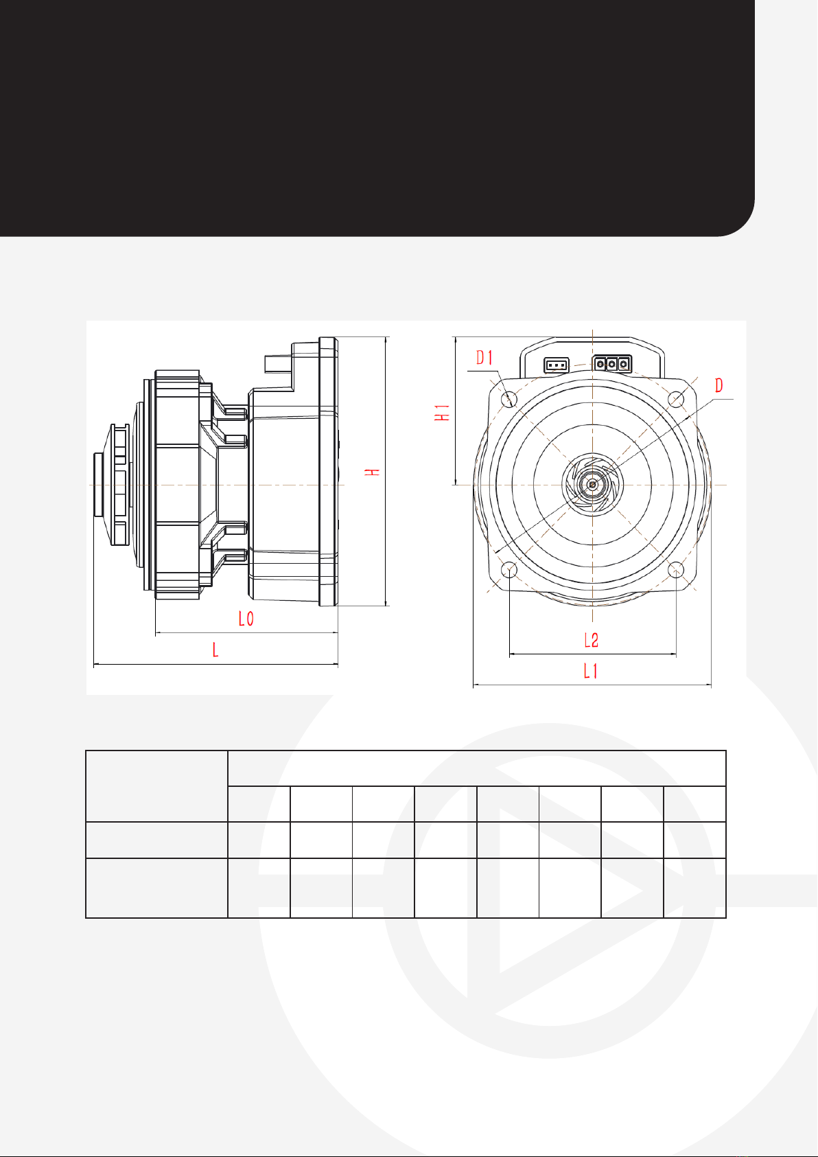
Pump Dimensions
Model Dimension (mm)
H H1 L L0 L1 L2 D D1
GBPHR/8/CW 109 60 102 76 99 69 98 6.5
GBPHR/8/
CCW 109 60 102 76 99 68 96 5.5
Fig. 6

10
Electrical Connection
Electrical
connection
Connection
signal PWM
1. Installation position 2. Position the AC
& PWM cable plugs
towards the control box
sockets and firmly insert
3. Completed assembly
The Tucson GBPHR/8/CCW is compatible and interchangable with the
following pump models:
PWM
- Grundfos®UPM3
- Grundfos®UPM2
- Grundfos®ALFA2
- Grundfos®UPS
- Grundfos®UPS2
(The Tucson GBPHR/8/CCW is compatible
as a replacement head on a PWM
controlled or non-PWM controlled pump)
68mm
This manual suits for next models
1
Table of contents


