Tuffcare P460 User manual

R
Rh
hi
in
no
o
S
St
ta
an
nd
d
U
Up
p
P
Pa
at
ti
ie
en
nt
t
L
Li
if
ft
te
er
r
P
P4
46
60
0,
,
P
P4
46
65
5
O
Op
pe
er
ra
at
ti
in
ng
g
M
Ma
an
nu
ua
al
l
© TUFFCARE, INC. ALL RIGHTS RESERVED RHINO ELECTRIC STAND UP LIFT_V1.0TW
WWW.TUFFCARE.COM
ATTENTION
Before using this Medical Device read this manual. If you are unable to
understand, contact your equipment provider for technical support before
attempting to use this product.

TABLE OF CONTENTS
TABLE OF CONTENTS
Table of Contents 1
Specifications 2
Product Diagram 3 - 4
General Guidelines 5 - 8
Assembly
Assembling the Mast Assembly to the Base 9 - 10
Attach the Up-Down Actuator to the Mast 11
Attaching the Knee Pad 12
Attaching the Power Base Actuator 13 - 14
Attaching the Control Unit on Mounting Bracket 15
Attaching the Battery Pack on Control Unit 17 - 18
Attaching Pendant and Actuator to Control Unit 19
Charging The Battery 20 - 21
Operation 22 - 25
Lifting the Patient 26 - 28
Transfering the Patient 29
Attaching Slings to Lift 30
Attaching Standing Sling 31 - 32
Attaching Buttock Strap 33
Attaching Transport Standing Sling 34
Lift Sling Type Reference 35 - 36
Maintenance 37
Limited Warranty 38
- 1 -
SPECIFICATIONS
SPECIFICATIONS
Height at end of Sling Lift Arm: 36 to 70 inches
Base Opening Between Legs: 21 1/2 to 35 inches
Base Clearance: 4 1/2 inches
Base Length: 40 inches
Overall Height: 70 inches
Overall Length: 40 inches
Overall Width: 26 inches
Casters: 3" Dual Front and 5" Rear with Brake
Sling Options: Polyester Standing or Transfer Sling
Weight Capacity: 350 I bs
Weight without Sling: P460 - 109 lbs, P465 -121 lbs
Battery: 24V DC (RCHBL)
Charger Input: l00-240V AC
Charger Output/Charging Time: 29.5V DC Max 6 hours
Motor Safety Devices: Anti-Entrapment
Emergency Stop Button: Yes
Limited Warranty Lifter/Electronics: 3 Years/1 Year
UNPACKING
UNPACKING
LDispose of the removed packaging at your local recycling
center. Discard the wrapper and box separately. Dispose of
the end-of-life item at a clean point.
LWhen cutting the zipties, be cautious not do damage the
braking wires.
LInspect for any damage and check for hardwares listed on
page 4 and 5 according to the device model.
- 2 -

- 3 -
A. Lift Arm B. Attachment (Sling) Cradle
C. Up-Down Actuator D. Knee Pad
E. Adjustable Base F. Dual Front Caster Wheels
G. Foot Step H. Foot Pedal for Base (P420)
I. Rear Caster Wheel with Brake
J. Charging Cord K. Frame Mast
L. Control Unit M. Push Handle Bar
N. Hand Pendant O. Battery Pack
PRODUCT DIAGRAM
PRODUCT DIAGRAM
AB
C
N
K
E
H
I
J
L
M
F
SEMI ELECTRIC PATIENT LIFTER P460
- 4 -
D
G
O
A. Lift Arm B. Attachment (Sling) Cradle
C. Up-Down Actuator D. Knee Pad
E. Adjustable Base F. Dual Front Caster Wheels
G. Foot Step H. Base Actuator (P465)
I. Rear Caster Wheel with Brake
J. Charging Cord K. Frame Mast
L. Control Unit M. Push Handle Bar
N. Hand Pendant O. Battery Pack
AB
C
N
K
E
H
I
J
L
M
F
SEMI ELECTRIC PATIENT LIFTER P465
D
G
O

- 5 -
DANGER! RISK OF ELECTRICAL AND FIRE HAZARD.
MAY RESULT IN DEATH, SERIOUS INJURY, SHOCK
OR BURNS.
This charger, like all electrical products. MUST be treated
with respect. Follow these instructions to reduce electrical
hazard risk.
TO HELP REDUCE THIS RISK:
PROPER GROUNDING OF AC POWER CORD
Charger MUST be grounded to reduce risk of electric
shock. Charger is equipped with an electric cord that has
an equipment grounding conductor and a grounding plug.
The plug MUST be plugged into an outlet that is properly
installed and grounded in accordance with all local codes
and ordinances. If you ever feel even a slight shock from
this or any electrical appliance, or equipment connected
to it, such as your chair or carrier STOP. Turn off electricity
to the outlet, and have it inspected by an electrician. You
may have a dangerous, improperly wired outlet.
DANGER - NEVER alter AC power cord or plug provided.
If it will not fit outlet, have a proper outlet installed by a
qualified electrician. Improper connection can result in a
risk of an electric shock. This battery charger is for use on
a nominal 120 volt circuit (common household current),
and has a grounding plug. A temporary adapter may be
used to connect this plug to a two- pole receptacle if a
properly grounded outlet is not available. The temporary
adapter should be used only until a qualified electrician
can install a properly grounded outlet.
Leg Adjusting Foot Pedal
(for P460 only)
Leg Adjusting Actuator
(for P465)
GENERAL GUIDELINES
GENERAL GUIDELINES
GENERAL GUIDELINES contains important information for
the safe operation and use of this Medical Device.
- 6 -
L WARNING
1. Check all parts for shipping damage before using. In
case of damage, DO NOT use the equipment.
2. The TUFFCARE patient lifter is NOT a transport
device. It is intended to transfer a patient from one
seated surface to another (such as from a bed to a
wheelchair).
3. DO NOT attempt to transfer until the user is assessed
by a qualified professional. Thoroughly read and fully
understand the instructions in this Owner’s Operating
Manual.
4. TUFFCARE transfer slings are specifically designed
to be used in conjunction with TUFFCARE patient lifters.
Slings and accessories designed by other manufacturers
are not to be utilized as a component of Tuffcare’s
patient lifter system.
5. The Rhino stand up lifter is intended to be used for
patient within weight limit indicated for the lifter. DO
NOT attempt to lift more than the weight limit indicated.

- 7 -
L WEIGHT LIMIT
DO NOT exceed maximum weight limit of the patient
lifter. The weight limit for the stand up patient lifter is
350lbs.
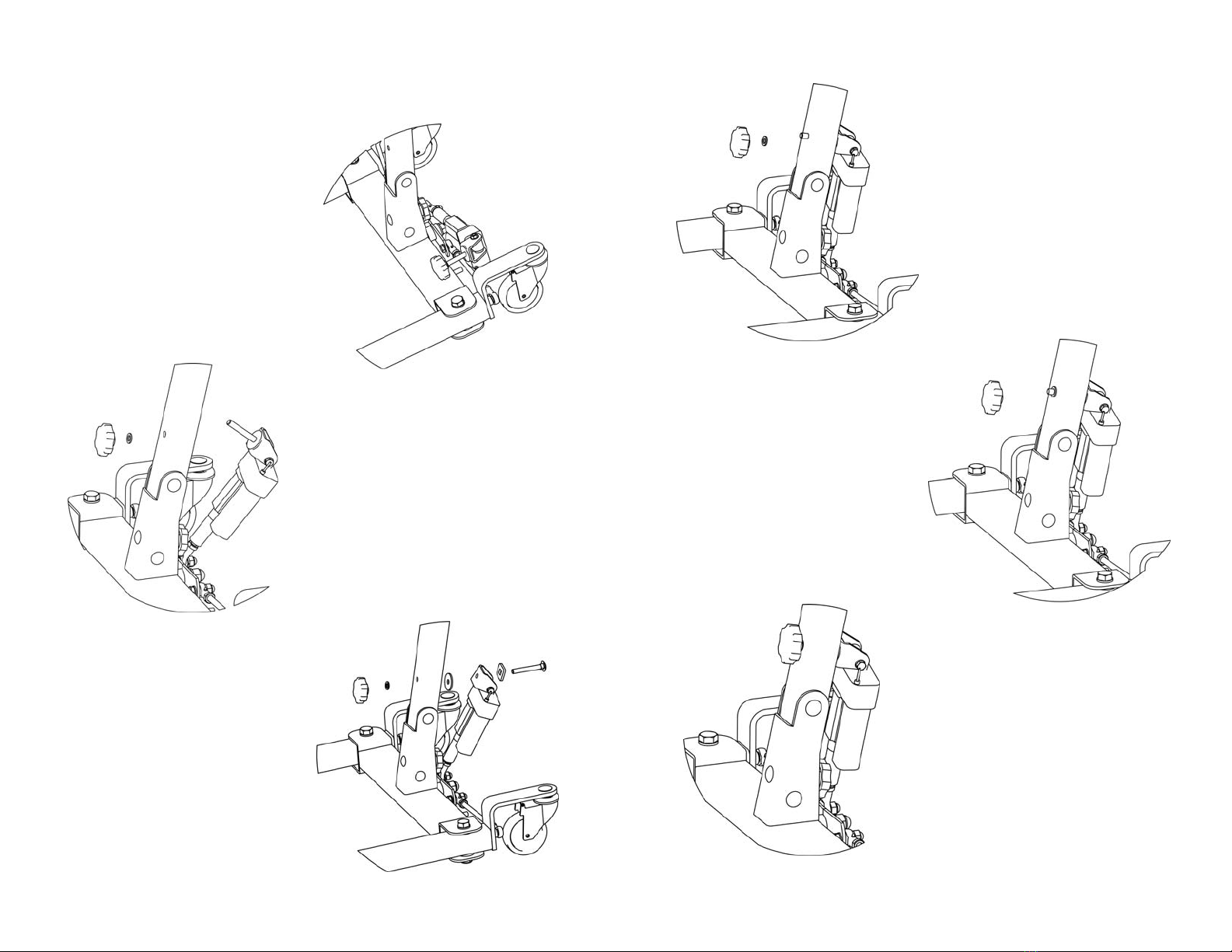
L ASSEMBLING THE LIFTER
DO NOT over-tighten mounting hardware. It will cause
damage to the mounting brackets.
L USING THE SLING
Before attaching the sling onto the attachment holders
on the lift arm, lift the hanging straps up to predetermine
which color coded hanging points to use in order to
avoid the sides of the sling riding up to the underarm
causing patient discomfort.
Be sure that sling is properly attached on sling holders
before the patient is removed from a bed, chair, or any
objects.
If the patient is in a wheelchair, secure the wheel locks
in place to prevent the chair from moving forwards or
backwards.
L OPERATING THE LIFTER
Prior to first use, make sure that battery is being fully
charged. Always use the handles to move the lifter.
L LIFTING THE PATIENT
Adjustments for safety and comfort should be made
before moving the patient. Patient’s arms should be
outside of the sling straps.
Before lifting a patient from a wheelchair, bed or any
objects, slightly raise the patient off the object and
check that sling attachments are secured.
During transfer, with the patient suspended in a sling
attached to the lifter, DO NOT roll the base over uneven
surfaces that would create an imbalance of the patient
lifter and could cause the patient lifter to tip over. Use
handle on the mast at all times to move the patient lifter.
- 8 -
TUFFCARE suggests locking the rear casters ONLY
when positioning or removing the sling (stand up or
transfer) from around the patient.
TUFFCARE DOES NOT suggest locking the rear casters
of the patient lifter when lifting a patient. When lift arm
rises the center of gravity will shift and caster wheels
will slightly move to balance the weight of the patient.
Locking the rear casters could cause the lifter to tip
over and endanger the patient and assistants.
L TRANSFERRING THE PATIENT
Before transferring, check that the lifter’s weight capacity
can withstand the patient’s weight.
Wheelchair wheel locks MUST be in a locked position
before lowering the patient into the wheelchair for
transport.
L PERFORMING MAINTENANCE
Regular maintenance of patient lifter and accessories is
required to assure proper operation.
Casters and axle bolts are also required to be checked
for tightness.
DO NOT over-tighten mounting hardware. It will cause
damage to the mounting brackets.
NOTE: See detail at Section 6 for maintenance.
L PINCH POINTS
Pinch points exist at base of lifter. Use caution, otherwise
injury could occur.

ASSEMBLING THE MAST ASSEMBLY TO THE BASE
1. Set the unit on the floor. Lock both
rear casters to prevent the base from
sliding before lifting up the mast.
2. With one person lift up and holding the mast, a second per-
son can assist in perform the securing the mast to the brack-
et on the base.
- 9 -
ASSEMBLY
ASSEMBLY
The lifter comes with pre-assembled main frame for easy
assembly
L WARNING
Use only Tuffcare parts to complete this stand up patient
lifter. Use team Lift! This is a heavy product, asssistance
is needed to preform the assembly.
- 10 -
3. Line up the hole between the mast and the middle of the
base bracket. Insert the carriage bolt through the holes and
secure with the lock nut and thick washer on the other side.
4. Insert the other carriage bolt through the lower side holes
from th right side, note that the hole on the right of the base
bracket is a squre hole. Then secure with the lock nut and
washer on the other side.
• Use the included wrench to secure and tighten all hardware.

ATTACH THE UP-DOWN ACTUATOR TO THE LIFT ARMT
L WARNING
Use only Tuffcare parts to complete this stand up patient
lifter. Use team Lift! This is a heavy product, asssistance
is needed to preform the assembly.
- 12 -
1. Unwrap the secure
straps on the actuator, with
one person holding to prevent
it from droping, a second person
lift up the lift arm and align the top
mounting holes on the actuator to
the bottom side actuator holder
on the lift arm.
2. Install the Clevis pin
through the top holes of
the up-down actuator and
arm bracket, use the
retaining ring on the orther
side to secure.
- 11 -
ATTACH THE KNEE PAD TO THE MAIN FRAME
1. Insert the knee pad
mounting tube onto the
receptacle tube locate
under the up and down
actuator. Secure with the
attached bolt and knob.
Use the holes on the
mounting tube to adjust
knee pad to suitable depth.
2. With the tube stop fac-
ing up, slide the the knee
pad over the top of the
mounting tube, slowly low-
ers it and line up the set-
ting pins on two sides with
the retainer holes. Adjust
to desirable height.
TUBE
STOP

- 13 -
ATTACH THE POWER BASE ACTUATOR TO THE MAST
ASSEMBLY (FOR P465 ONLY)
1. Locate the base actuator at
the space between the two
rear casters.
2. Turn counter clockwise to
remove the knob and the 1st
small flat washer that was on
top of the actuator through
bolt.
3. Install the bolt through the
hole in the mast. make sure
the 3 included washers are
lined up like the diagram.
4. Place the small flat washer
onto the bolt.
5. Follow by the threading the
knob onto the bolt.
5. Turn clockwise to tighten the
bolt, if needed use the included
wench(17mm) to hold the other
side of the bolt while turning.
- 14 -

- 15 -
ATTACHING DRIVE UNIT
L WARNING
Make sure there is an audible click when plugging battery
pack onto the control unit. Otherwise, injury or damage
may occur.
ATTACHING THE CONTROL UNIT ON THE MOUNTING
BRACKET
1. Temporarily remove the
controller setting screw from
the mounting plate.
2. Align the controller to the mounting plate at about a 5
degree angle.
3. Make sure the 2 grooves at the lower back of the controller
slide are positioned over the 2 extrusions at the bottom of the
mounting plate.
** Caution: Failure to do so will result in an inoperable state
of the unit. **
- 16 -

- 17 -
4. Place the controller mounting screw back into the same
place and tighten.
ATTACHING THE BATTERY PACK ON CONTROL UNIT
1. Hold the battery pack by its top handle on the backside
of the battery. There is a spring loaded lever latch under the
handle.
- 18 -
2. Set the battery pack on top of the controller at about a 5
degree angle.
3. While holding onto the lever latch inside the handle, move
the battery pack parallel to the controller.
4. Make sure the latch plate is lifted up and set over the 2
extrusions at the top of the mounting plate.
5. Release the hold on the spring loaded lever latch. You will
hear an audible click. The 2 holes on both sides of the latch
plate should set on the 2 extrusion points on top of the
mounting plate; securing the battery pack to the holder.
HANDLE

- 19 -
PREPARING THE PATIENT LIFT FOR USE
1. Plug the hand control, leg actuator (For P465 Power Base
Lifters Only) and up-down actuator into the receptacles on
the bottom of the control unit.
2. Check and tighten all hardware BEFORE operation.
3. Plug the power cord into common household 110 or 220
Volt AC receptacle to charge the battery.
Plug for Leg Actuator
For P465 only
Plug for Power Cord
Plug for Pendant
Plug for Up-Down Actuator
Control Unit
NOTE: When plugged into an AC outlet the safe protect
feature turns on disabling the control pendent from
functioning. The unit will not function while plugged in.
- 20 -
CHARGING THE BATTERY
NOTE: It is suggested to recharge the battery daily to prolong
its life cycle.
1. Place the battery on the control unit to charge battery.
Push the top of the battery against the mounting bracket until
there is an audible click, See more details on pages (15-16)
for Attaching the Battery Pack onto the Control Unit.
2. Make sure the red emergency button is fully pulled out and
at the on position. (When emergency button is pressed down,
the circuit is off and the unit will not function or charge.
3. Plug the power code into a 110 Volt outlet.
NOTE: When plugged into an AC outlet the safe protect feature
turns on, disabling the control pendent from functioning. The
unit will not function while plugged in.
NOTE: The charge LED will light up red while charging.
When fully charged, the LED will stop illuminating.
NOTE: It will take approximately (4) hours to charge a battery
that requires a full charge.
When the charging power cord is plugged into an electrical
outlet, the red LED light on the left of the battery will come on.
When the built-in charging system senses a drop in battery
voltage,then the charging system automatically increases its
output to re-charge the battery.

- 21 -
The bars on the battery meter will begin to flash based on the
remaining percentage of the charge, the flashing bar slowly
increases when the battery is taking charge. This indicates
that the battery is charging on a fast mode “Bulk Charge”.
Fast charging usually last for 30 min.
NOTE: If the charging cord is plugged in and the battery
meter does not indicate this it suggests the circuit is off, the
battery is fully charged, or a faulty battery(Have the battery
pack replaced).
When the battery reserve reaches a desirable level the battery
meter stops flashing and the LED turns from red to green.
Now the battery meter will indicate a full gauge when all the
bars light up. At this time the charger utilizes a slow charging
“Absorption Charge”, leave charging for 4 to 6 hours.
When the battery becomes fully charged, the battery meter
indicator bars turn off. Unplug the charging cord and the lifter
will be ready for use.
- 22 -
OPERATION
OPERATION
L WARNING
DO NOT attempt to transfer until the user is assessed by
a qualified professional. Thoroughly read and fully
understand the instructions in this Owner’s Manual.
LOCKING/UNLOCKING THE REAR CASTERS
RAISING/LOWERING THE PATIENT LIFT
Controls the
Hi-low section
PRESS To Raise
the
Patient Lift
PRESS To Lower
the
Patient Lift
P460 P465
LOCK UNLOCK

- 23 -
CLOSING/OPENING THE LEGS
To Open and Close the Legs on P460
Step down on left side of “Leg Adjusting Stepper” to close the legs
Step down on right side of “Leg Adjusting Stepper” to open the leg.
To Open and Close the Legs on P465
Press the open and close button on
the hand control.
USING THE CIRCUIT OFF/EMERGENCY STOP
RED emergency button on Control Unit
OFF/ Push the RED emergency
button in to stop the lift arms from
raising or lowering.
ON/ To reset, rotate the emergency
button clockwise, an audible click
can be heard when the circuit is
engaged.
Red button out = Powered On, Red button pushed in = Power Off
NOTE: When emergency button is pressed down, the circuit
is off and the unit will not function or charge.
- 24 -
ADJUSTING CALF PAD POSITION
ELEVATE THE FOOT STEP
There are 3 depth and 5 height adjustment on the knee pad
mounting tube to accomadate users of different figure.
1. Use the holes on the mounting tube to adjust knee pad to
suitable depth.
2. Pull the setting pins out to free the knee pad. Slowly move
knee pad up and down to desirable height. Line up the pins
with holes on the sides, release pins and lock.
Lift the foot step up to get it out of the way when use for rehab
walking.
2
2
1

- 26 -- 25 -
LIFTING THE PATIENT
LIFTING THE PATIENT
L WARNING
1. DO NOT exceed the maximum weight limit of
450/650 lbs
2.DO NOT attempt to transfer until the user is assessed
by a qualified professional. Thoroughly read and fully
understand the instructions in this Owner’s Manual.
3. ALWAYS keep hands and fingers clear of moving
parts to avoid injury. Individuals that use the universal
patient sling MUST be able to support their own weight,
otherwise injury may occur.
4. DO NOT move the patient if the patient lift sling is not
properly connected to the attachment hooks on the lifting
bar. Check that the patient sling is properly connected
to the attachment holders BEFORE lifting the patient.
5. During transfer, with the patient suspended in the
patient sling, DO NOT roll the base of the patient lifter
over any uneven surfaces that would cause the patient
lifter to become unstable.
6. ALWAYS use the handle on the mast assembly to
move the patient lifter to ensure the safety of the user.
ACTIVATING A MECHANICAL EMERGENCY RELEASE
Emergency Release
To activate the emergency release, pull-down the Red Knob
located on the top-end of Up-Down actuator drive shift.
1. Rotate the Red Knob clockwise to slowly lower down the
lift arm.
2. Trun the Red Knob counter-clockwise to slowly lift up the
lift arm.
.
3. Push the emergency red release knob back up reengage
the gears for normal operation.

- 28 -- 27 -
2. Position the patient lifter using the handle on the mast.
3. Press the “ LIFT” – “DOWN” button on the hand control to
lower the lift arms for easy attachment to the sling.
Press “DOWN”
symbol bottom
to lower arms
for attachment
HANDLES
POSITIONING THE PATIENT LIFTER
1. Open the leg section of the floor lift to obtain stability.
FOR P460: Step down on right side of “Leg Adjusting
Stepper” to open the legs to the maximum open position.
Step down on right to OPEN
FOR P465:
Press the “FOOT” – “OPEN” symbol
button on the hand control to open
the legs to the maximum open
position.
L WARNING
The legs of the patient lifter MUST be in the maximum
open position for stability and safety.
Maximum
Inside Open
is 34”

- 29 - - 30 -
Tall Medium
Short
Transport
Attaching Slings to Stand-Up Lift
All Tuffcare’s Rhino slings have
four color coded hanging points
on the straps. Place the straps of
the sling over attach points of the
lift arm. Match the corresponding
colors on each side of the sling
for an even lift of the patient.
Use the color coded hangers to
place the patient in various angle
positions.
Black
Purple
Green
Blue
Tuffcare’s Rhino Stand-Up Lift’s lift arm has three attachment knobs per
side. Use the above chart as a guideline to determine best attachment point.
Warning!
Do not move the patient if the sling is not properly connected to the
attachment points of the lift. Check that the sling is properly connected
to the attachment points prior to lifting a patient. Attachment points
include swivel bar, straps, S‐hooks and D or O‐rings. If any attachments
are not properly in place, correct the problem. When the sling is elevated
a few inches off the stationary surface and before moving the patient,
check again to make sure that all sling attachments are secure. If any
attachments are not properly in place, lower the patient back onto the
stationary surface and correct this problem ‐ otherwise, injury or damage
may occur.
Attach Suggest
Point Height
Short > 5’6”
Medium 5’6” - 5’10”
Tall 5’10”
L WARNING
DO NOT attempt to transfer until the user is assessed
by a qualified professional. Thoroughly read and fully
understand the instructions in this Owner’s Manual.
DO NOT move the patient if the straps on the sling are
not properly connected to the attachment hooks of the
patient lifter. Check that the sling is properly connected
to the attachment hooks prior to lifting a patient.
DO NOT use patient slings and patient lifter of different
manufacturers. TUFFCARE slings are made specifically
for use with TUFFCARE floor type patient lifter.
Otherwise, injury or damage may occur. The legs of the
patient lifter MUST be in the maximum open position for
optimum stability and safety.
Be sure to check the sling attachments each time the
sling is removed and replaced to ensure that it is properly
attached before the patient is removed from a surface.
TRANSFERRING THE PATIENT
NOTE: Tuffcare recommends that two assistants be used
when transferring a patient to a wheelchair. Ensure the legs
of the lifter (with patient) are in the maximum open position.

- 32 -- 31 -
Before lifting the patient, make sure that the bottom edge of the standing
sling is positioned on the lower back of the patient and the patient's arms
are outside the standing sling. Check that the sling is properly connected
to the attachment points prior to lifting a patient. When the patient is
being elevated a few inches off the stationary surface and before moving
the patient, check again to make sure that all sling attachments are secure.
If any attachments are not properly in place, lower the patient back onto
the stationary surface to secure the attachment.
Depending on the strength of
individual patient, rise the lift
arm to desired height. Do not
over lift patient as it may
cause injury to the patient.
Determine the best attachment point for the standing sling on each lift
arm. Use the chart on page 30 as a guideline to determine attachment
point. Always use the color coded strap on the standing sling closest to
the patient while still maintaining patient stability and comfort. Make
sure the color coded strap sits flush against the attachment knob.
*Once it is in the proper place, have the
user lean back into the standing sling so
the weight is centered on their back.
This allows the sling to pull them up
without having it slide up and put the
weight and strain on the user's under-
arms.
Attach Standing Sling

- 34 -- 33 -
Make sure the color coded strap sits flush against the attachment knob.
Loop the hanging strap on both end of the buttock strap on to the transport
attachment in the middle of the lift arm.
*Once it is in the proper place, have the user lean back into the standing
sling so the weight is centered on their back. This allows the sling to pull
them up without having it slide up and put the weight and strain on the
user's underarms.
Before lifting the patient, make sure that
the bottom edge of the standing sling is
positioned on the lower back of the
patient and the patient's arms are outside
the standing sling. Check that the sling is
properly connected to the attachment
points prior to lifting a patient. When the
patient is elevated a few inches off the
stationary surface and before moving the
patient, check again to make sure that all
sling attachments are secure. If any
attachments are not properly in place,
lower the patient back onto the stationary
surface to secure the attachment.
Attach Buttock Strap
Before lifting the patient, make
sure that the bottom edge of the
standing sling is positioned on the
lower back of the patient and the
patient's arms are outside the
standing sling. Check that the
sling is properly connected to the
attachment points prior to lifting a
patient. When the patient is elevated
a few inches off the stationary
surface and before moving the
patient, check again to make sure
that all sling attachments are
secure. If any attachments are not
properly in place, lower the
patient back onto the stationary
surface to secure the attachment.
Determine the best attachment point for the standing sling on each lift
arm. Use the chart on page 32 as a guideline to determine attachment
point. Always use the color coded strap on the standing sling closest to
the patient while still maintaining patient stability and comfort. Make
sure the color coded strap sits flush against the attachment knob.
Attach Transport Standing Sling

LIFT SLING TYPE REFERENCE
Tuffcare Rhino stand up lift slings are made with a three layer
soft but sturdy polyester fabric which provides comfort and
protects patients who may have sensitive skin. Along with
preventing the patient from sliding in the sling, our Tuffcare
Rhino slings are universal and will accommodate any 2, 4 or
6 point lift arm from other suppliers.
- 35 - - 36 -
Model# Size A B C Recommend
Weight
P141 M 68” 16” 38” 99 - 210 lbs
P142 L 74” 16” 44” 198 - 315 lbs
P143 XL 84” 16” 58” 310 - 450 lbs
Belt: medium 22”- 40”, large 35”- 53”, x large 40”- 60”
STANDING SLING is designed to be used only with a stand up lift only.
It will accommodate patients who have weight bearing capacity along with
head and neck control and are able to bend at the knees, hip and ankles.
Our Tuffcare standing sling provides patient dependence along with effective
easy transferring a patient from the bed to a toilet, shower chair or chair.
Model# Size A B C Recommend
Weight
P147 L 35” 71” 7.5” 99 - 450 lbs
BUTTOCK STRAP is to be used in conjunction with a universal sling
and not to be used by itself. The buttock strap works perfect for those
days that the patient needs some extra help and security while using there
sit to stand lift. The buttock strap works by placing the strap underneath
the patients’ bottom and this will allow the patient to sit in the buttock strap
like a swing and will relieve some of the extra weight on their legs.
C
A
B
C
B
A
Model# Size A B C Recommend
Weight
P152 L 34” 14” 40” 99 - 300 lbs
P153 XL 46” 14” 44” 225 - 450 lbs
TRANSPORT STANDING SLING is designed to be used only with a
stand up sling. It will accommodate patients who have weight bearing
capacity along with head and neck control and are able to bend at the hip,
knees and ankles an can sit up on the edge of the bed surface. The Transport
standing sling is used for simple transfers or transporting patients for longer
distances while being in a seated position and will accommodate toileting
due to its large opening.
A
B
C
L WARNING
When elevated a few inches off the seating surface of
the wheelchair and before moving the patient, check
again to make sure that all hardware and straps/chains
are properly connected. If any attachments are NOT
properly in place, lower the patient completely to cor-
rect this problem.
Adjustments for safety and comfort should be made
before moving the patient. Patient’s arms should be
inside of the chains or straps.
TUFFCARE slings and Hardware are designed specially
for use with TUFFCARE Patient Lifter. For the safety of
the patient, DO NOT intermix slings and patient lifter of
different manufacturers.

- 38 -
LIMITED WARRANTY
LIMITED WARRANTY
The warranty below has been drafted to comply with Federal Law applicable
to products manufactured after July 4, 1975. This warranty is extended
only to the original purchaser/consumer (or dealer non-consumer who
does not buy for resale).
Tuffcare®warrants that it’s Rhino Series patient lifters will be free from
defective workmanship and materials for a period of three (3) years following
the date of original manufacture with the following exceptions: All welds
are warranted for the life of the lift. Electronics on the lifters are warranted
for one (1) year. The warranty period commences on the original manufacture
date. If within such warranty period any such product proven to Tuffcare®
satisfaction to be defective, such product will be repaired or replaced at
Tuffcare®option.
Tuffcare®sole obligation and your exclusive remedy under this warranty
shall be limited to such repair and/or replacement. This warranty does not
include any labor charges incurred in replacement parts installation.
Freight charges to the factory are at the expense of the consumer or seller.
Return freight charges will be prepaid by Tuffcare®. For warranty service,
please contact the authorized dealer from whom you purchased your
Tuffcare®products. In the event that you do not receive satisfactory warranty
service, please write directly to: Tuffcare®: 4977 La Palma Ave, Anaheim,
California, 92807. DO NOT RETURN PRODUCTS WITHOUT PRIOR
AUTHORIZATION.
LIMITATIONS AND EXCLUSIONS: The foregoing warranty shall not
apply to products subjected to negligence, abuse, misuse, improper operation,
improper maintenance, improper storage or damages beyond Tuffcare®
control. The evaluation will be solely determined by Tuffcare®. The warranty
shall not apply to problems arising from normal wear, or failure to follow
instructions, or if parts are not manufactured by Tuffcare®, or do not comply
with original equipment specifications that are added to Tuffcare®product.
THE FOREGOING WARRANTY IS EXCLUSIVE AND IN LIEU OF ALL
OTHER WARRANTIES, INCLUDING BUT NOT LIMITED TO THE
IMPLIED WARRANTIES OF MERCHANTABILITY AND FITNESS FOR A
PARTICULAR PURPOSE AND SHALL NOT EXTEND BEYOND THE
DURATION OF THE EXPRESS WARRANTY PROVIDED HEREIN.
TUFFCARE®SHALL NOT BE LIABLE FOR ANY CONSEQUENTIAL OR
INCIDENTAL
DAMAGES WHATSOEVER.
This warranty gives you specific rights and you may also have other legal
rights which vary from state to state. Some states do not allow the exclusion
or limitations of incidental or consequential damage, or limitation on how
long an implied warranty
- 37 -
MAINTENANCE
MAINTENANCE
CLEANING THE LIFT
• The lift can be cleaned with non-abrasive cleaners.
Make sure that the wheels are free of hair, lint and
other debris.
DETECTING WEAR AND DAMAGE
• Check monthly that all screws are tight and have not
loosened.
• Check monthly for damaged or exposed wires on the
electrical components.
• Inspect monthly for signs of cracking, fraying, or any
deterioration.
• Contact your equipment provider for replacement of
any defective parts immediately and ensure that the
lift is not used until repair job is completed.
LUBRICATING THE LIFT
• A light grease lubricant may be applied to the ball
bearing and swivel of the casters every three months.
PERFORMING REGULAR MAINTENANCE
• Regular maintenance of the lift and accessories is
required to ensure proper operation. The casters and
axle bolts are also required to be checked for proper
tightness.
This manual suits for next models
1
Table of contents
Other Tuffcare Mobility Aid manuals
Popular Mobility Aid manuals by other brands

Moretti
Moretti EASYRED SL2040 Instructions for installation and use

WY'EAST MEDICAL
WY'EAST MEDICAL AERIAL 600 Basic operations

EZee Life
EZee Life CH1052 instructions

Antar
Antar AT51013 user manual

LiftSeat
LiftSeat Independence Owner's operator and maintenance manual

NRS Healthcare
NRS Healthcare Mowbray M11089 User instructions