Tunstall 77 3411 00 User manual

00 8804 48, 05/21 (Rev. 3.0) - 1 -
© Tunstall GmbH, Orkotten 66, 48291 Telgte, Germany, www.tunstall.de
DE - Installationsanleitung EN - Installation Instructions
USV-Steuergerät 10A, Bestell-Nr. 77 3411 00 UPS Control unit 10A, Order no. 77 3411 00
Vor Inbetriebnahme lesen!
Bitte lesen Sie diese Warnungen und Hinweise sorgfältig durch, bevor
Sie das Gerät in Betrieb nehmen. Bewahren Sie die Anleitung zum
Nachlesen auf. Das Gerät darf nur durch fachkundiges und qualifizier-
tes Personal installiert werden. Bei Funktionsstörungen oder Beschä-
digungen schalten Sie sofort die Versorgungsspannung ab und senden
das Gerät zur Überprüfung ins Werk. Das Gerät beinhaltet keine Ser-
vicebauteile. Die angegebenen Daten dienen allein der Produktbe-
schreibung und sind nicht als zugesicherte Eigenschaften im
Rechtssinne aufzufassen. Im Zweifelsfall gilt der englische Text.
Read this first!
Before operating this device, please read this manual thoroughly and
retain this manual for future reference! This device may only be in-
stalled and put into operation by qualified personnel. If damage or
malfunction should occur during operation, immediately turn power
off and send device to the factory for inspection. The device does not
contain serviceable parts. The information presented in this docu-
ment is believed to be accurate and reliable and may change without
notice. For any clarifications the English translation will be used.
WARNUNG! Missachtung nachfolgender Punkte
kann einen elektrischen Schlag, Brände, schwere
Unfälle oder Tod zur Folge haben:
Schalten Sie die Eingangsspannung vor Installations-, Wartungs-
oder Änderungsarbeiten ab und sichern Sie diese gegen unbeab-
sichtigtes Wiedereinschalten.
Führen Sie keine Änderungen oder Reparaturversuche am Gerät
durch. Gerät nicht öffnen!
Verhindern Sie das Eindringen von Fremdkörpern, wie z.B. Büro-
klammern und Metallteilen.
Betreiben Sie das Gerät nicht in feuchter Umgebung oder in einer
Umgebung, bei der mit Betauung oder Kondensation zu rechnen
ist.
Gehäuse nicht während des Betriebes oder kurz nach dem Ab-
schalten berühren. Heiße Oberflächen können Verletzungen ver-
ursachen.
WARNING! Risk of electrical shock, fire, personal
injury, or death:
Turn power off before working on the device. Protect against in-
advertent re-powering.
Do not open, modify or repair the device.
Use caution to prevent any foreign objects from entering the
housing.
Do not use in wet locations or in areas where moisture or conden-
sation can be expected.
Do not touch during power-on and immediately after power-off.
Hot surfaces may cause burns.
Produktbeschreibung
Das USV-Steuergerät 10A (77 3411 00) dient in Kombination mit einem
24Vdc-Netzgerät und einer externen 12V-Batterie zur Überbrückung
von Stromausfällen. Wenn das Netzgerät genügend Spannung liefert,
lädt das USV-Steuergerät die Batterie auf. Bei Ausfall der Versorgungs-
spannung wird die in der Batterie gespeicherte Energie in einem gere-
gelten Prozess an die Last abgegeben.
Product Description
The 77341100 is an uninterruptible power supply controller (DC-UPS),
which is used in combination with a 24V power supply and one external
12V-battery to bridge power failures. When the power supply provides
sufficient voltages, the DC-UPS controller charges the battery. When
the power supply voltage fails, the energy stored in the battery is re-
leased to the DC bus in a regulated process.
Bestimmungsgemäßer Gebrauch
Dieses Gerät ist für den Einbau in ein Gehäuse vorgesehen und vorge-
sehen für den gewerblichen Einsatz, wie z.B. in industriellen Steuerun-
gen, Prozesssteuerungen, Überwachungs- und Messgeräten oder
dergleichen. In Anlagen, in denen eine Fehlfunktion oder ein Ausfall
dieses Gerätes zu schweren Verletzungen führen oder Menschenleben
gefährden kann, darf dieses Gerät nur dann verwendet werden, wenn
vor Ort technische und/oder organisatorische Maßnahmen getroffen
werden, die die Folgen der Fehlfunktion ausgleichen.
Intended Use
This device is designed for installation in an enclosure and is intended
for commercial use, such as in industrial control, process control, mon-
itoring and measurement equipment or the like. In systems where fail-
ure or failure of this equipment may cause serious injury or endanger
human life, this equipment must be used only if technical and / or or-
ganizational measures are taken to correct the effects of the malfunc-
tion.
Funktionsschaltbild Functional Diagram
Wichtiger Hinweis für Rufanlagen
Die Norm DIN VDE 0834 für Rufanlagen fordert die Einhaltung der
EN 60601-1 bzgl. der elektrischen Sicherheit. Das bedeutet: Das 24Vdc-
Netzgerät muss geerdet werden. Alle anderen Geräte der modularen
Spannungsversorgung, z.B. das USV-Steuergerät 10 A (77341100), müs-
sen isoliert gegenüber der Schutzerde (PE) montiert werden. Empfeh-
lung für die isolierte Montage: Montieren Sie das USV-Steuergerät auf
eine DIN-Schienenerhöhung HAGER HYA036 (Best.-Nr. 76090004, Brei-
te 106mm). Zusätzlich muss von dem isoliert montierten Gerät 1cm Ab-
stand zu allen geerdeten Flächen und Geräten eingehalten werden.
Important note for nurse call systems
The German standard DIN VDE 0834 for nurse call systems requires
compliance with EN 60601-1 regarding electrical safety. This means:
The 24V power supply unit must be earthed. All other devices of the
modular power supply, e.g. the UPS control unit 10 A (77341100), must
be mounted insulated against protective earth (PE). Recommendation
for insulated mounting: Install the UPS control unit on a DIN rail raiser
HAGER HYA036 (order no. 76090004, width 106mm). In addition, a dis-
tance of 1cm must be maintained from the insulated mounted device
to all earthed surfaces and equipment.
Aufwärts-
wandler
Ladeeinheit
Elektron.
Strom-
Ausgang
LED „Diagnosis“
LED „Status“
Controller
LED „Check Wiring“
Kontakt „Buffering“
Kontakt „Ready“
(1)
(2)
(3)
(4)
(5)
(6)
Kontakt
„Replace Baery“
Eingang
-
+
-
+
+
-
12V
Baerie
begrenzer
Verpolungs-
sicherung,
Eingangs-
schutz
strom-
Rück-
schutz
Baerie-
tester
Baerie-
relais
Trenn-
End-of-charge
Voltage
Buffer-me Limiter
(7)
(8)
Inhibit +
Inhibit -
Boost
Converter
Charger
Electronic
Current
Output
Diagnosis LED
Status LED
Controller
Check Wiring LED
Buffering Contact
Ready Contact
(1)
(2)
(3)
(4)
(5)
(6)
Replace Baery
Contact
Input
-
+
-
+
+
-
12V
Baery
Limiter
Polarity
Reverse
Input Fuse,
Protecon
Current
Return
Protecon
Baery
Tester
Baery
Relay
Disconnect
End-of-charge
Voltage
Buffer-me Limiter
(7)
(8)
Inhibit +
Inhibit -

00 8804 48, 05/21 (Rev. 3.0) - 2 -
© Tunstall GmbH, Orkotten 66, 48291 Telgte, Germany, www.tunstall.de
Installationsanleitung
Schalten Sie die Spannungsversorgung aus und entfernen Sie die Batte-
riesicherung, bevor Sie an dem Gerät arbeiten.
Installieren Sie das Gerät in einem Gehäuse, das vor elektrischen, me-
chanischen und Brandgefahren schützt.
Installieren Sie das Gerät so auf eine DIN-Schiene nach EN 60715, dass
sich die Eingangsklemmen an der Oberseite des Gerätes befinden.
Der Eingang kann von einem geregelten Netzgerät oder einer ähnlichen
Gleichstromquelle mit Strom versorgt werden. Die Spannung zwischen
Eingang und Erde darf 60Vdc nicht dauerhaft überschreiten.
(WARNUNG! Bei Rufanlagen darf die Schutzerde (PE) nicht an das USV-
Steuergerät angeschlossen werden.) Die Welligkeitsspannung im Nie-
derfrequenzbereich zwischen 50Hz und 10kHz muss bei der Verwen-
dung in Schiffsanwendungen vernachlässigbar sein.
Der Eingang muss von einer PELV- oder SELV-Quelle oder einem „iso-
lierten Sekundärkreis“ versorgt werden, um einen SELV- oder PELV-
Ausgang aufrechtzuerhalten.
Verwenden Sie ein entsprechend dimensioniertes 24V-Netzgerät, das
den zusätzlichen internen Stromverbrauch liefern kann, der zum Laden
der Batterie benötigt wird.
Verwenden Sie nur VRLA-Bleibatterien mit einer Kapazität zwischen
3,9Ah und 40Ah.
Überprüfen Sie den Eingang und die Batterie auf korrekte Polung. Das
Gerät funktioniert nicht, wenn die Pole vertauscht sind.
Stellen Sie sicher, dass die Verdrahtung korrekt ist, indem Sie alle loka-
len und nationalen Vorschriften befolgen. Verwenden Sie geeignete
Kupferkabel, die für eine Mindestbetriebstemperatur von 60°C für Um-
gebungstemperaturenbis +45°C, 75°C für Umgebungstemperaturen bis
+60°C und 90°C für Umgebungstemperaturen bis +70°C ausgelegt sind.
Achten Sie darauf, dass alle Einzeldrähte einer Litze in den Klemmenan-
schluss gelangen.
Die Querschnittsfläche der verwendeten Adern darf nicht kleiner als
2,5mm² (oder AWG 12) sein. Die Länge der Adern darf nicht mehr als
2x1,5 m zwischen der Batterie und dem USV-Steuergerät betragen. Län-
gere oder kleinere Drähte können die Leistung des Systems verändern.
Verwenden Sie eine 30A Sicherung (ATOF® 287 030 von Littelfuse oder
eine UL-gelistete Sicherung mit den gleichen Eigenschaften) im Batte-
riestromkreis. Die Batteriesicherung schützt die Adern zwischen der
Batterie und dem USV-Steuergerät und muss sich nahe an der Batterie
befinden.
Das Gerät ist für Bereiche des Verschmutzungsgrades 2 in kontrollier-
ten Umgebungen ausgelegt. Kondensation oder Frostbildung sind nicht
erlaubt.
Das Gerät ist als Gerät der „Schutzklasse III“ nach IEC 61140 ausgeführt.
Das Gehäuse des Gerätes bietet eine Schutzart von IP20.
Für den Eingang und den Batterieeingang des Geräts ist eine Trennvor-
richtung vorzusehen.
Das Gerät ist für Konvektionskühlung ausgelegt und benötigt keinen ex-
ternen Lüfter. Behindern Sie die Luftzirkulation nicht, und verdecken
Sie die Lüftungsgitter nicht!
Halten Sie die folgenden minimalen Einbauabstände ein: 40mm oben,
20mm unten, 5mm auf der linken und rechten Seite. Erhöhen Sie diesen
Abstand von 5mm auf 15mm, wenn das benachbarte Gerät eine Wär-
mequelle ist. Wenn das Gerät dauerhaft mit weniger als 50% belastet
wird, können die 5mm auf Null reduziert werden.
Installation Instructions
Turn power off and disconnect the battery fuse before working on the
device.
Install the device in an enclosure providing protection against electrical,
mechanical and fire hazards.
Install the device onto a DIN-rail according to EN 60715 with the input
terminals on the top of the unit.
The input can be powered from a regulated power supply or a similar
DC source. The voltage between the input and ground must not exceed
60Vdc continuously. (WARNING! For nurse call systems, the protective
earth (PE) must not be connected to the UPS control unit.) The ripple
voltage in the low frequency range between 50Hz and 10kHz must be
negligible when used in marine applications.
The input must be powered from a PELV or SELV source or an “Isolated
Secondary Circuit” in order to maintain a SELV or PELV output.
Use an appropriately sized 24V power supply, which can deliver the ad-
ditional internal current consumption, required to charge the battery.
Use only VRLA lead acid batteries with a capacity between 3.9Ah and
40Ah.
Check for correct input and battery polarity. The device will not operate
when the voltage is reversed.
Make sure that the wiring is correct by following all local and national
codes. Use appropriate copper cables that are designed for a minimum
operating temperature of 60°C for ambient temperatures up to +45°C,
75°C for ambient temperatures up to +60°C and 90°C for ambient tem-
peratures up to +70°C. Ensure that all strands of a stranded wire enter
the terminal connection.
Do not use wires smaller than 2.5mm² (or AWG 12) and not longer than
2x1.5m between the battery and the DC-UPS controller. Longer or
smaller gauge wires can change performance of the system.
Use a 30A fuse (ATOF® 287 030 from Littelfuse or an UL listed fuse with
the same characteristics) in the battery circuit. The battery fuse pro-
tects the wires between the battery and the DC-UPS and shall be locat-
ed close to the battery.
The device is designed for pollution degree 2 areas in controlled envi-
ronments. No condensation or frost is allowed.
The device is designed as “Class of Protection III” equipment according
to IEC 61140.
The enclosure of the device provides a degree of protection of IP20.
A disconnecting means shall be provided for the input and the battery
input of the device.
The device is designed for convection cooling and does not require an
external fan. Do not obstruct airflow and do not cover ventilation grid!
Keep the following minimum installation clearances: 40mm on top,
20mm on the bottom, 5mm left and right side. Increase the 5mm to
15mm in case the adjacent device is a heat source. When the device is
permanently loaded with less than 50%, the 5mm can be reduced to ze-
ro.
The device is designed for altitudes up to 6000m (19685ft).
The maximum surrounding air temperature is +70°C (+158°F). The op-
erational temperature is the same as the ambient or surrounding air
temperature and is defined 2cm below the device.
The device is designed to operate in areas between 5% and 95% relative
humidity.
Anschlussdiagramm Wiring Scheme
Das Gerät ist für Höhen bis zu 6000 m ausgelegt.
... Fortsetzung auf der nächsten Seite...
DE - Installationsanleitung EN - Installation Instructions
Signale
OutputInput
Last
Ausgang
Eingang
+
-
+
-
+
-
+
-
Ba.
+
-
L
NL
PE
24V 12V 24V
-
+
-
+
Netzgerät
z.B.
77 3410 00
oder
77 3410 50
12V-Baerie
Sicherung
max. 30A
max. 2x1,5m
min. 2,5mm²
(12AWG)
USV-Steuergerät
77 3411 00
12V
Baeriemodul
z.B. 77 3412 00
Eingang Ausgang
Signals
OutputInput
Load
Output
Input
+
-
+
-
+
-
+
-
Ba.
+
-
L
NL
PE
24V 12V 24V
-
+
-
+
Power Supply
e.g.
77 3410 00
or
77 3410 50
12V Baery
Fuse
max. 30A
max. 2x1.5m
min. 2.5mm²
(12AWG)
DC-UPS
77 3411 00
12V
Baery Module
e.g. 77 3412 00

00 8804 48, 05/21 (Rev. 3.0) - 3 -
© Tunstall GmbH, Orkotten 66, 48291 Telgte, Germany, www.tunstall.de
Die maximale Umgebungslufttemperatur beträgt +70°C. Die Betriebs-
temperatur ist dieselbe wie die Umgebungs- oder Umgebungslufttem-
peratur und ist definiert 2 cm unter dem Gerät.
Das Gerät ist für den Betrieb in Bereichen zwischen 5% und 95% relati-
ver Luftfeuchtigkeit ausgelegt.
Installationshinweise für explosionsgefährdete Bereiche
Das Gerät ist für den Einsatz in Bereichen der Klasse I Division 2 Grup-
pen A, B, C, D und für den Einsatz in Umgebungen der Gruppe II Katego-
rie 3 (Zone 2) geeignet. Klassifizierung des explosionsgefährdeten
Bereichs: ATEX: EPS 15 ATEX 1 025 X, II 3G EX ec nC IIC T3 Gc
WARNUNG EXPLOSIONSGEFAHR!
Der Austausch von Bauteilen kann die Eignung für diese Umgebung be-
einträchtigen. Klemmen Sie das Gerät nicht ab und verändern Sie keine
Geräteeinstellungen, es sei denn, die Stromversorgung ist abgeschaltet
oder der Bereich ist eindeutig nicht explosionsgefährdet. Für das End-
produkt muss ein geeignetes Gehäuse vorgesehen werden, das mindes-
tens über Schutzart IP54 verfügt und die Anforderungen gemäß EN
60079-0 erfüllt.
Installation Instructions for Hazardous Location Areas
The device is suitable for use in Class I Division 2 Groups A, B, C, D loca-
tions and for use in Group II Category 3 (Zone 2) environments.
Hazardous Location Classification: ATEX: EPS 15 ATEX 1 025 X, II 3G EX
ec nC IIC T3 Gc
WARNING EXPLOSION HAZARDS!
Substitution of components may impair suitability for this environment.
Do not disconnect the device or change unit settings unless power has
been switched off or the area is known to be non-hazardous.
A suitable enclosure must be provided for the end product which has a
minimum protection of IP54 and fulfils the requirements of the EN
60079-0.
Funktionsbeschreibung
Der Ausgang ist elektronisch gegen Leerlauf, Überlast und Kurzschluss
geschützt und kann jede Art von Lasten versorgen, einschließlich unbe-
grenzter induktiver und kapazitiver Lasten.
Legen Sie keine Rückspannungen vom Verbraucher an die Ausgangs-
klemmen größer als 35V an.
Grüne Status-LED („Status“)
Diese LED leuchtet, wenn die Batterie mehr als 85% geladen ist. Wäh-
rend des Ladevorgangs blinkt die LED mit einer langsamen Frequenz.
Schnelles Blinken ist eine Anzeige für ein Pufferereignis.
Gelbe Diagnose-LED („Diagnosis“)
Diese LED meldet eine Überlastsituation, eine abgelaufene Pufferzeit
(blinkt 15 Minuten lang), einen aktivierten Inhibit-Eingang (Sperrein-
gang) oder wenn die Batterie ersetzt werden soll.
Rote LED „Verdrahtung prüfen“ („Check Wiring“)
Diese LED zeigt einen Fehler in der Installation an, wie z.B. zu niedrige
Eingangs- oder Batteriespannung, falsche Verdrahtung, durchgebrann-
te oder fehlende Batteriesicherung.
Functional Description
The output is electronically protected against no-load, overload and
short circuit and can supply any kind of loads, including unlimited induc-
tive loads and capacitive loads.
Do not apply return voltages from the load to the output terminals
higher than 35V.
Green Status LED
This LED is on solid, when the battery is charged more than 85%. During
battery charging, the LED is flashing with a slow frequency and rapid
flashing is an indication of a buffer event.
Yellow Diagnosis LED
This LED reports an overload situation, an expired buffer time (flashes
for 15 minutes), an activated inhibit input or when the battery should
be replaced.
Red Check Wiring LED
This LED indicates a failure in the installation such as too low input or
battery voltage, incorrect wiring, blown or missing battery fuse.
Pufferzeitbegrenzer („Buffer-time Limiter“)
Mit dem Einstellrad „Pufferzeitbegrenzer“ auf der Vorderseite des Ge-
rätes wird die maximale Pufferzeit bei einem Pufferereignis begrenzt.
10s, 30s, 1min, 3min, 10min oder unbegrenzt können eingestellt wer-
den. Dies kann Batterieenergie sparen, um schneller aufzuladen und
die Lebensdauer der Batterie zu verlängern. Wenn das Einstellrad auf
„unbegrenzt“ eingestellt ist, wird die Pufferung fortgesetzt, bis der Tief-
entladeschutz für die Batterie die Pufferung stoppt.
... Fortsetzung auf der nächsten Seite...
Buffer-time Limiter
The buffer time during a buffer event can be set to 10s, 30s, 1min, 3min,
10min or infinity with the dial on the front. This can save battery energy
for faster recharge and expand the lifetime of the battery. When dial is
set to infinity, buffering continues until stopped by the battery deep-
discharge protection.
...Continuation on the next page...
DE - Installationsanleitung EN - Installation Instructions
Grüne Status-LED:
Gelbe Diagnose-LED:
Rote LED „Verdrahtung prüfen“:
Bereit
Es wird geladen
Pufferbetrieb
Stromüberlast
Baerie muss ersetzt werden
Pufferzeit ist abgelaufen
Inhibit akv
Störung
Overload
Replace Baery
Buffer Time Expired
Inhibit Acve
Red "Check Wiring" LED:
Fault
Yellow "Diagnosis" LED:
Ready
Charging
Green "Status" LED:
Buffering
LED-Blinkmuster LED Signal Paern

00 8804 48, 05/21 (Rev. 3.0) - 4 -
© Tunstall GmbH, Orkotten 66, 48291 Telgte, Germany, www.tunstall.de
Ladeschluss-Spannung („End-of-charge Voltage“)
Die Ladeschlussspannung muss entsprechend der voraussichtlichen
Temperatur am Standort der Batterie manuell eingestellt werden. Mit
dem Einstellrad auf der Vorderseite kann eine Temperatur zwischen
+10 und +40°C eingestellt werden. Stellen Sie im Zweifelsfall das Gerät
auf 40°C ein.
Inhibit-Eingang („Inhibit“)
Der Inhibit-Eingang deaktiviert oder stoppt die Pufferung. Im Stromver-
sorgungsbetrieb ist ein statisches Signal von 10-30V erforderlich. Im
Pufferbetrieb ist ein Impuls von 10-30V mit einer Mindestlänge von
250ms erforderlich, um die Pufferung zu stoppen. Der Strom des Inhi-
bit-Eingangs wird durch das USV-Steuergerät auf 6mA begrenzt.
Relaiskontakte für Bereit, Pufferung und Batterie ersetzen
Der Kontakt „Bereit“ („Ready“) ist geschlossen, wenn die Batterie zu
85% geladen ist und das Gerät bereit zum Puffern ist.
Der Kontakt „Pufferung“ („Buffering“) ist geschlossen, wenn das Gerät
im Pufferbetrieb arbeitet.
Der Kontakt „Batterie ersetzen“ („Replace Battery“) ist geschlossen,
wenn ein Ersetzen der Batterie erforderlich ist.
Kontaktwerte: 60Vdc 0,3A, 30Vdc 1A, 30Vac 0,5A für ohmsche Lasten.
End-of-charge Voltage
The end-of-charge-voltage shall be set according to the expected tem-
perature in which the battery is located. The dial on the front allows a
setting between +10 and +40°C. If in doubt, set the unit to 40°C.
Inhibit Input
The inhibit input disables or stops buffering. In power supply mode, a
continuous input of 10-30V is required. During buffering, a short input
of 10-30V for at least 250ms is required to stop buffering. The current
of the inhibit input is limited to 6mA by the DC-UPS control unit.
Ready, Buffering and Replace Battery Relay Contacts
The Ready contact is closed when the battery is 85% charged and the
unit is ready to buffer.
The Buffering contact is closed when the unit is in buffer mode.
The Replace Battery contact is closed when a battery replacement is
necessary.
Contact ratings: 60Vdc 0.3A, 30Vdc 1A, 30Vac 0.5A for resistive loads.
Technische Daten
Alle Werte sind typische Werte, angegeben für 24Vdc Eingangsspan-
nung, 10A Ausgangsstrom im Stromversorgungsbetrieb bei 25°C Umge-
bung, kein Aufladen und nach einer Aufwärmzeit von 5 Minuten, sofern
nicht anders angegeben.
Technical data
All values are typical figures specified at 24Vdc input voltage, 10A out-
put current in power supply mode at 25°C ambient, no charging and af-
ter a 5 minutes run-in time unless otherwise noted.
DE - Installationsanleitung EN - Installation Instructions
Eingangsspannung DC 24V -20%/+25%
Min. Eingangsspan-
nung, um das Laden zu
starten und den Batte-
riebetrieb zu aktivieren
22,8Vdc
Transferspannung zum
Umschalten in den Bat-
teriebetrieb
22,5Vdc
Interne Stromauf-
nahme 1,1A Inkl. Ladestrom
Ausgang im Stromversorgungsbetrieb:
Spannungsabfall von
Eingang zu Ausgang 230mV Bei 10A Ausgangslast
330mV Bei 15A Ausgangslast
Ausgangsstrom 15A Unter +60°C
11,3A Bei +70°C
Lineare Abnahme zwischen +60 und +70°C
Ausgang im Batteriebetrieb:
Ausgangsspannung 22,45V Bei keiner Ausgangslast
22,25V Bei 10A Ausgangslast
Ausgangsstrom 10A Unter +60°C
7,5A Bei +70°C
Lineare Abnahme zwischen +60 und +70°C
15A Kurzzeitig, bis zu 5s
Verlustleistung 5,5W Bei 10A Ausgangslast
Temperaturbereich -25°C bis +70°C
Max. Drahtquerschnitt
(Litze) 4mm² Stromanschlussklemmen
American Wire Gauge AWG 20-10 Stromanschlussklemmen
Max. Drahtdurchmes-
ser 2,8mm Stromanschlussklemmen
Abisolierlänge 10mm Stromanschlussklemmen
Max. Drahtquerschnitt
(Litze) 1,5mm² Signalklemmen
American Wire Gauge AWG 24-16 Signalklemmen
Max. Drahtdurchmes-
ser 1,5mm Signalklemmen
Abisolierlänge 6mm Signalklemmen
Anzugsmoment 0,4Nm Signalklemmen
Abmessungen (HxBxT) 124x49x117
mm Ohne DIN-Schiene
Gewicht 530g
Input voltage DC 24V -20%/+25%
Minimum input volt-
age to start charging
and to enable battery
mode
22.8Vdc
Transfer voltage to
switch into battery
mode
22.5Vdc
Internal current con-
sumption 1.1A Includes charging current
Output in power supply mode:
Input to output voltage
loss 230mV At 10A output load
330mV At 15A output load
Output current 15A Below +60°C
11.3A At +70°C
Derate linearly between +60°C and +70°C
Output in battery mode:
Output voltage 22.45V At no output load
22.25V At 10A output load
Output current 10A Below +60°C
7.5A At +70°C
Derate linearly between +60°C and +70°C
15A Short term, up to 5s
Power losses 5.5W At 10A output load
Temperature range -25°C to +70°C
Max. wire size
(litz wire) 4mm² For power terminals
Wire size AWG AWG 20-10 For power terminals
Max. wire diameter 2.8mm For power terminals
Wire stripping length 10mm/ 0.4inch For power terminals
Max. wire size
(litz wire) 1.5mm² For signal terminals
Wire size AWG AWG 22-14 For signal terminals
Max. wire diameter 1.5mm For signal terminals
Wire stripping length 6mm/ 0.25inch For signal terminals
Tightening torque 0.4Nm/
3.5lb.inch For signal terminals
Size (wxhxd) 49x124x117
mm Without DIN-rail
Weight 530g / 1.17lb

00 8804 48, 05/21 (Rev. 3.0) - 5 -
© Tunstall GmbH, Orkotten 66, 48291 Telgte, Germany, www.tunstall.de
FR - Mode d'installation EN - Installation Instructions
Unité de contrôle ASI 10A, Réf. 77 3411 00 UPS Control unit 10A, Order no. 77 3411 00
A lire avant mise sous tension !
Veuillez lire ces instructions de montage et d'entretien avant de
mettre l'alimentation sous tension. Conservez ce manuel qui vous
sera toujours utile. Cette alimentation ne doit être installée que par
du personnel qualifié et compétent. En cas de dommage ou dysfonc-
tionnement, coupez immédiatement l’alimentation et retournez l’ap-
pareil à l’usine pour vérification ! L’alimentation ne contient pas de
pièces échangeables Les données indiquées dans ce document
servent uniquement à donner une description du produit et n'ont au-
cune valeur juridique. En cas de divergences, le texte anglais fait foi.
Read this first!
Before operating this device, please read this manual thoroughly and
retain this manual for future reference! This device may only be in-
stalled and put into operation by qualified personnel. If damage or
malfunction should occur during operation, immediately turn power
off and send device to the factory for inspection. The device does not
contain serviceable parts. The information presented in this docu-
ment is believed to be accurate and reliable and may change without
notice. For any clarifications the English translation will be used.
AVERTISSEMENT ! Prendre en compte les points sui-
vants, afin d'éviter toute détérioration électrique,
risque d’incendie, dommage corporels ou blessures
mortelles :
Mettre l’alimentation hors tension avant toute intervention sur
celle-ci et s'assurer qu'il n'y a pas risque de redémarrage.
Ne pas ouvrir, modifier ou réparer l'alimentation.
Veiller à ce qu'aucun objet ne rentre en contact avec l'intérieur de
l'alimentation (trombones, pièces métalliques).
Ne pas faire fonctionner l'appareil dans un environnement hu-
mide ou dans un environnement où il peut y avoir de la conden-
sation.
Ne pas toucher le carter pendant le fonctionnement ou directe-
ment après la mise hors tension. Surface chaude risquant d’en-
traîner des blessures.
WARNING! Risk of electrical shock, fire, personal
injury, or death:
Turn power off before working on the device. Protect against in-
advertent re-powering.
Do not open, modify or repair the device.
Use caution to prevent any foreign objects from entering the
housing.
Do not use in wet locations or in areas where moisture or conden-
sation can be expected.
Do not touch during power-on and immediately after power-off.
Hot surfaces may cause burns.
Description du produit
Le 77341100 est un contrôleur d’alimentation de secours, qui est utilisé
en combinaison avec un bloc d’alimentation 24V et une batterie ex-
terne 12V pour pallier les pannes de courant. Lorsque le bloc d'alimen-
tation fournit suffisamment de tension, l’unité de commande ASI 10A
charge la batterie. Lorsque la tension d'alimentation tombe en panne,
l'énergie stockée dans la batterie fourni les consommateurs en proces-
sus de charge régulée.
Product Description
The 77341100 is an uninterruptible power supply controller (DC-UPS),
which is used in combination with a 24V power supply and one external
12V-battery to bridge power failures. When the power supply provides
sufficient voltages, the DC-UPS controller charges the battery. When
the power supply voltage fails, the energy stored in the battery is re-
leased to the DC bus in a regulated process.
Utilisation conforme
Cet appareil est conçu pour être installé dans un boîtier et est destiné à
un usage commercial, par exemple dans les équipements de contrôle
industriel, de contrôle de processus, de surveillance et de mesure ou
équipements similaires. Dans les systèmes où un dysfonctionnement
ou une panne de cet appareil pourrait causer des blessures graves ou
un risque de décès, cet appareil ne doit être utilisé que si des mesures
techniques et/ou organisationnelles sont prises pour compenser les ef-
fets du dysfonctionnement.
Intended Use
This device is designed for installation in an enclosure and is intended
for commercial use, such as in industrial control, process control, mon-
itoring and measurement equipment or the like. In systems where fail-
ure or failure of this equipment may cause serious injury or endanger
human life, this equipment must be used only if technical and / or or-
ganizational measures are taken to correct the effects of the malfunc-
tion.
Schéma fonctionnel Functional Diagram
Remarque importante pour les systèmes d'appel malade
La norme allemande DIN VDE 0834 pour les systèmes d'appel malade
exige la conformité à la norme EN 60601-1 en matière de sécurité élec-
trique. Cela signifie que le bloc d'alimentation 24Vdc doit être mis à la
terre. Tous les autres appareils de l'alimentation modulaire, par
exemple l'unité de contrôle ASI 10A (77341100), doivent être montés
isolés de la terre de protection (PE). Recommandation pour le montage
isolé : Monter l'unité de contrôle ASI sur une rehausse rail DIN HAGER
HYA036 (référence 76090004, largeur 106mm). En outre, une distance
de 1 cm doit être maintenue entre l’appareil monté isolé et toutes les
surfaces et appareils mis à la terre.
Important note for nurse call systems
The German standard DIN VDE 0834 for nurse call systems requires
compliance with EN 60601-1 regarding electrical safety. This means:
The 24V power supply unit must be earthed. All other devices of the
modular power supply, e.g. the UPS control unit 10 A (77341100), must
be mounted insulated against protective earth (PE). Recommendation
for insulated mounting: Install the UPS control unit on a DIN rail raiser
HAGER HYA036 (order no. 76090004, width 106mm). In addition, a dis-
tance of 1cm must be maintained from the insulated mounted device
to all earthed surfaces and equipment.
Conversseur
élévateur
de baerie
Limiteur
électronique
Sore
LED « Diagnosis »
LED « Status »
Controller
LED « Check Wiring »
Contact « Buffering »
Contact « Ready »
(1)
(2)
(3)
(4)
(5)
(6)
Contact
« Replace Baery »
Entrée
-
+
-
+
+
-
12V
Baerie
de courant
Protecon de
Fusible
d‘entrée,
polarité inverse
de courant
Protecon
de retour
Chargeur
de baerie
Testeur
déconnexion
Relais de
End-of-charge
Voltage
Buffer-me Limiter
(7)
(8)
Inhibit +
Inhibit -
Boost
Converter
Charger
Electronic
Current
Output
Diagnosis LED
Status LED
Controller
Check Wiring LED
Buffering Contact
Ready Contact
(1)
(2)
(3)
(4)
(5)
(6)
Replace Baery
Contact
Input
-
+
-
+
+
-
12V
Baery
Limiter
Polarity
Reverse
Input Fuse,
Protecon
Current
Return
Protecon
Baery
Tester
Baery
Relay
Disconnect
End-of-charge
Voltage
Buffer-me Limiter
(7)
(8)
Inhibit +
Inhibit -

00 8804 48, 05/21 (Rev. 3.0) - 6 -
© Tunstall GmbH, Orkotten 66, 48291 Telgte, Germany, www.tunstall.de
Instruction d’installation
Mettre l'appareil hors tension et débrancher le fusible de la batterie
avant de travailler sur l'appareil.
Installer l'appareil dans un boîtier offrant une protection contre les
risques électriques, mécaniques et d'incendie.
Monter l'appareil sur un rail DIN selon EN 60715 de telle sorte que les
bornes d'entrée se trouvent sur la face supérieure de l'appareil.
L'entrée peut être alimentée par un bloc d'alimentation régulé ou une
source de courant continu similaire. La tension entre l'entrée et la terre
ne doit pas dépasser 60Vdc en continu. ( AVERTISSEMENT ! Pour les sys-
tèmes d'appel malade, la terre de protection (PE) ne doit pas être
connectée à l'unité de contrôle ASI .) La tension d'ondulation dans la
gamme de basses fréquences comprise entre 50 Hz et 10 kHz doit être
négligeable lorsqu'il est utilisé dans des applications marines.
L'entrée doit être alimentée par une source PELV ou SELV ou un "circuit
secondaire isolé" afin de maintenir une sortie SELV ou PELV.
Utiliser un bloc d'alimentation 24 V de taille appropriée, qui peut four-
nir la consommation de courant interne supplémentaire nécessaire
pour charger la batterie.
Utiliser uniquement des batteries au plomb-acide VRLA d'une capacité
comprise entre 3,9Ah et 40Ah.
Vérifier la bonne polarité de l'entrée et de la batterie. L'appareil ne
fonctionne pas lorsque la lorsque la polarité est inversée.
S'assurer que le câblage est correct en suivant tous les codes locaux et
nationaux. Utiliser des câbles en cuivre appropriés, conçus pour une
température de fonctionnement minimale de 60°C pour des tempéra-
tures ambiantes jusqu'à +45°C, 75°C pour des températures ambiantes
jusqu'à +60°C et 90°C pour des températures ambiantes jusqu'à +70°C.
S'assurer que tous les fils d'un toron entrent dans le bornier.
Ne pas utiliser de fils plus petits que 2,5mm² et pas plus longs que
2x1,5m entre la batterie et l’unité de commande ASI. Des fils plus longs
ou plus petits peuvent modifier les performances du système.
Utiliser un fusible 30A (ATOF® 287 030 de Littelfuse ou un fusible homo-
logué UL avec les mêmes caractéristiques) dans le circuit de la batterie.
Le fusible de batterie protège les fils entre la batterie et l’unité de com-
mande ASI et doit être situé près de la batterie.
L'appareil est conçu pour les zones de degré de pollution 2 dans des en-
vironnements contrôlés. Il ne faut aucune condensation ou gelée.
L'appareil est conçu comme un appareil de "classe de protection III" se-
lon CEI 61140.
Le boîtier de l'appareil offre un indice de protection IP20.
Un dispositif de déconnexion doit être prévu pour l'entrée de l’appareil
et l'entrée de la batterie de l’appareil.
L'appareil est conçu pour le refroidissement par convection et ne né-
cessite pas de ventilateur externe. Ne pas obstruer le flux d'air et ne pas
couvrir la grille de ventilation !
Respecter les distances de montage minimales suivantes : 40mm en
haut, 20mm en bas, 5mm à gauche et à droite. Augmenter cette dis-
tance de 5mm à 15mm si l'appareil adjacent est une source de chaleur.
Si l'appareil est chargé en permanence avec moins de 50%, les 5mm
peuvent être réduits à zéro.
L'appareil est conçu pour des altitudes allant jusqu'à 6000m.
La température maximale de l'air ambiant est de +70°C. La température
de fonctionnement est la même que la température ambiante ou la
température de l'air ambiant et est définie à 2 cm sous l'appareil.
L'appareil est conçu pour fonctionner dans des zones entre 5% et 95%
d'humidité relative.
Installation Instructions
Turn power off and disconnect the battery fuse before working on the
device.
Install the device in an enclosure providing protection against electrical,
mechanical and fire hazards.
Install the device onto a DIN-rail according to EN 60715 with the input
terminals on the top of the unit.
The input can be powered from a regulated power supply or a similar
DC source. The voltage between the input and ground must not exceed
60Vdc continuously. (WARNING! For nurse call systems, the protective
earth (PE) must not be connected to the UPS control unit.) The ripple
voltage in the low frequency range between 50Hz and 10kHz must be
negligible when used in marine applications.
The input must be powered from a PELV or SELV source or an “Isolated
Secondary Circuit” in order to maintain a SELV or PELV output.
Use an appropriately sized 24V power supply, which can deliver the ad-
ditional internal current consumption, required to charge the battery.
Use only VRLA lead acid batteries with a capacity between 3.9Ah and
40Ah.
Check for correct input and battery polarity. The device will not operate
when the voltage is reversed.
Make sure that the wiring is correct by following all local and national
codes. Use appropriate copper cables that are designed for a minimum
operating temperature of 60°C for ambient temperatures up to +45°C,
75°C for ambient temperatures up to +60°C and 90°C for ambient tem-
peratures up to +70°C. Ensure that all strands of a stranded wire enter
the terminal connection.
Do not use wires smaller than 2.5mm² (or AWG 12) and not longer than
2x1.5m between the battery and the DC-UPS controller. Longer or
smaller gauge wires can change performance of the system.
Use a 30A fuse (ATOF® 287 030 from Littelfuse or an UL listed fuse with
the same characteristics) in the battery circuit. The battery fuse pro-
tects the wires between the battery and the DC-UPS and shall be locat-
ed close to the battery.
The device is designed for pollution degree 2 areas in controlled envi-
ronments. No condensation or frost is allowed.
The device is designed as “Class of Protection III” equipment according
to IEC 61140.
The enclosure of the device provides a degree of protection of IP20.
A disconnecting means shall be provided for the input and the battery
input of the device.
The device is designed for convection cooling and does not require an
external fan. Do not obstruct airflow and do not cover ventilation grid!
Keep the following minimum installation clearances: 40mm on top,
20mm on the bottom, 5mm left and right side. Increase the 5mm to
15mm in case the adjacent device is a heat source. When the device is
permanently loaded with less than 50%, the 5mm can be reduced to ze-
ro.
The device is designed for altitudes up to 6000m (19685ft).
The maximum surrounding air temperature is +70°C (+158°F). The op-
erational temperature is the same as the ambient or surrounding air
temperature and is defined 2cm below the device.
The device is designed to operate in areas between 5% and 95% relative
humidity.
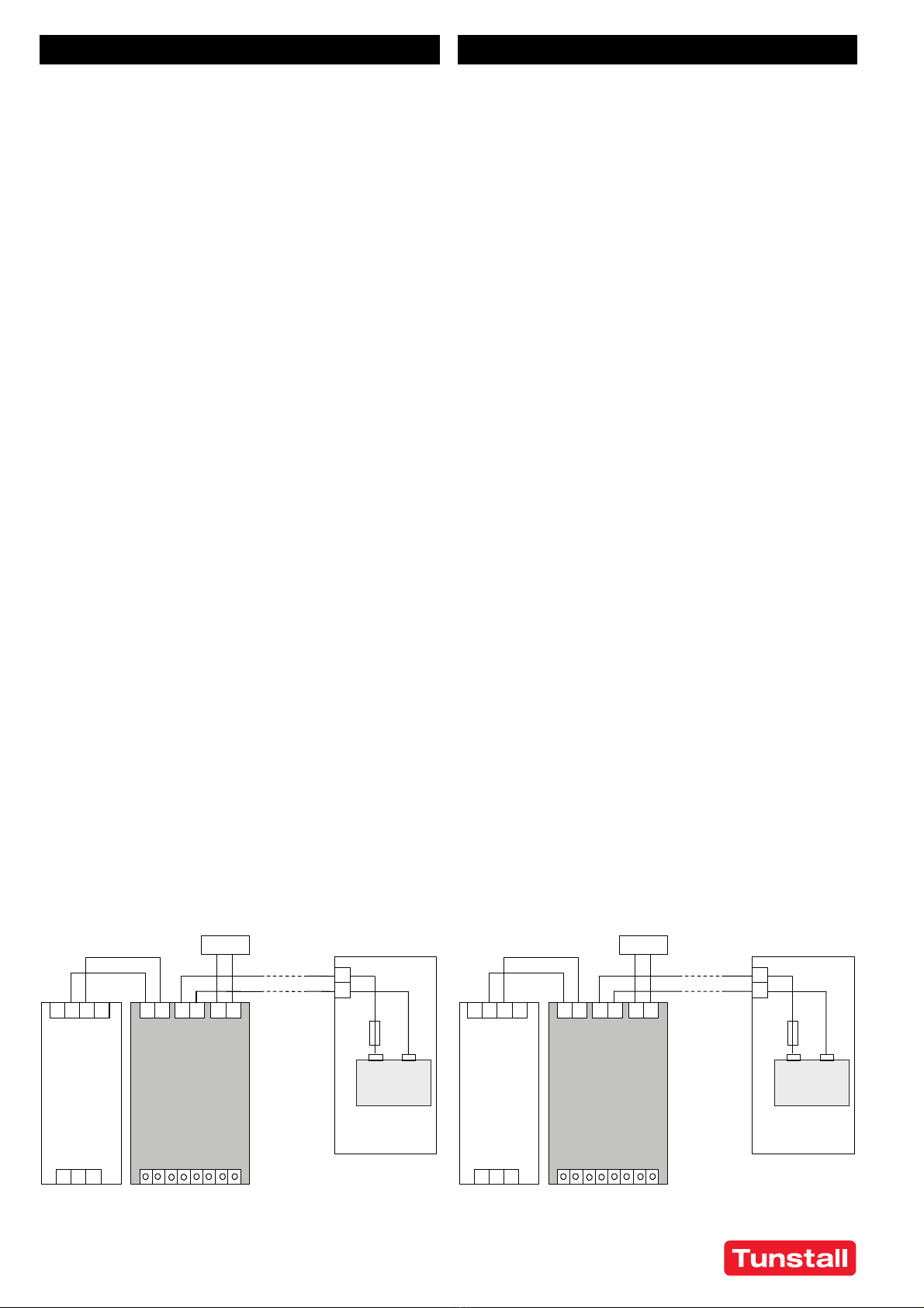
Schéma de branchement Wiring scheme
FR - Mode d'installation EN - Installation Instructions
Signaux
OutputInput
Charge
Sore
Entrée
+
-
+
-
+
-
+
-
Ba.
+
-
L
NL
PE
24V 12V 24V
-
+
-
+
Bloc
d‘alimentaon
p.ex.
77 3410 00
ou
77 3410 50
Baerie 12V
Fusible
30A max.
2x1,5m max.
2,5mm² min.
(12AWG)
Unité de contrôle
ASI
77 3411 00 12V
Module de baerie
p.ex. 77 3412 00
Entrée Sore
Signals
OutputInput
Load
Output
Input
+
-
+
-
+
-
+
-
Ba.
+
-
L
NL
PE
24V 12V 24V
-
+
-
+
Power Supply
e.g.
77 3410 00
or
77 3410 50
12V Baery
Fuse
max. 30A
max. 2x1.5m
min. 2.5mm²
(12AWG)
DC-UPS
77 3411 00
12V
Baery Module
e.g. 77 3412 00

00 8804 48, 05/21 (Rev. 3.0) - 7 -
© Tunstall GmbH, Orkotten 66, 48291 Telgte, Germany, www.tunstall.de
Instructions d'installation pour les zones à risques
d'explosion
L'appareil peut être utilisé dans des endroits de Classe I, Division 2,
Groupes A, B, C, D et dans des environnements du Groupe II, Catégorie
3 (Zone 2). Classification des emplacements dangereux : ATEX: EPS 15
ATEX 1 025 X, II 3G EX ec nC IIC T3 Gc.
AVERTISSEMENT RISQUES D'EXPLOSION !
Le remplacement de composants peut nuire à l’adéquation de l'appa-
reil à cet environnement. Ne pas déconnecter l’appareil et ne pas mo-
difier les réglages de l'appareil à moins que l'alimentation n'ait été
coupée ou que la zone ne soit reconnue comme non dangereuse. Un
boîtier approprié doit être prévu pour le produit final qui a un indice de
protection minimum IP54 et qui est conforme aux exigences de la
norme EN 60079-0.
Installation Instructions for Hazardous Location Areas
The device is suitable for use in Class I Division 2 Groups A, B, C, D loca-
tions and for use in Group II Category 3 (Zone 2) environments.
Hazardous Location Classification: ATEX: EPS 15 ATEX 1 025 X, II 3G EX
ec nC IIC T3 Gc.
WARNING EXPLOSION HAZARDS!
Substitution of components may impair suitability for this environment.
Do not disconnect the device or change unit settings unless power has
been switched off or the area is known to be non-hazardous.
A suitable enclosure must be provided for the end product which has a
minimum protection of IP54 and fulfils the requirements of the EN
60079-0.
Description fonctionnelle
La sortie est protégée électroniquement contre les surcharges et les
court-circuits et peut alimenter tout type de charge, y compris des
charges inductives et capacitives illimitées.
Ne pas appliquer de tensions de retour de la charge aux bornes de sor-
tie supérieures à 35V.
LED d'état verte ( « Status » )
Cette LED s'allume lorsque la batterie est chargée à plus de 85%. Pen-
dant la charge, la LED clignote à une fréquence lente. Un clignotement
rapide indique qu'il s'agit d'un événement buffering.
LED de diagnostic jaune ( « Diagnosis » )
Cette LED indique une situation de surcharge, un temps de buffering
écoulé (clignote pendant 15 minutes), une entrée d’inhibition activée
ou lorsque la batterie doit être remplacée.
LED rouge « Vérifier le câblage » ( « Check wiring » )
Cette LED indique une erreur dans l'installation, telle qu'une tension
d'entrée ou de batterie faible, un câblage incorrect, un fusible de batte-
rie grillé ou manquant.
Functional Description
The output is electronically protected against no-load, overload and
short circuit and can supply any kind of loads, including unlimited induc-
tive loads and capacitive loads.
Do not apply return voltages from the load to the output terminals
higher than 35V.
Green Status LED
This LED is on solid, when the battery is charged more than 85%. During
battery charging, the LED is flashing with a slow frequency and rapid
flashing is an indication of a buffer event.
Yellow Diagnosis LED
This LED reports an overload situation, an expired buffer time (flashes
for 15 minutes), an activated inhibit input or when the battery should
be replaced.
Red Check Wiring LED
This LED indicates a failure in the installation such as too low input or
battery voltage, incorrect wiring, blown or missing battery fuse.
Limiteur de temps de buffering (« Buffer-time Limiter »)
La durée de la période de buffer pendant un événement buffering peut
être réglée sur 10s, 30s, 1min, 3min, 10min ou à infini avec le sélecteur
sur le devant. Cela permet d'économiser l'énergie de la batterie pour
une recharge plus rapide et prolonger la durée de vie de la batterie.
Lorsque le sélecteur est réglé à l'infini, la période de buffer continue
jusqu'à l'arrêt par la protection de décharge profonde de la batterie.
Buffer-time Limiter
The buffer time during a buffer event can be set to 10s, 30s, 1min, 3min,
10min or infinity with the dial on the front. This can save battery energy
for faster recharge and expand the lifetime of the battery. When dial is
set to infinity, buffering continues until stopped by the battery deep-
discharge protection.
Tension de fin de charge (« End-of-charge Voltage »)
La tension de fin de charge doit être réglée en fonction de la tempéra-
ture prévue à l'emplacement de la batterie. Le sélecteur sur le devant
permet de régler la température entre +10°C et +40°C. En cas de doute,
régler le sélecteur à 40°C.
End-of-charge Voltage
The end-of-charge-voltage shall be set according to the expected tem-
perature in which the battery is located. The dial on the front allows a
setting between +10 and +40°C. If in doubt, set the unit to 40°C.
FR - Mode d'installation EN - Installation Instructions
LED d‘état verte :
LED de diagnosc jaune :
LED rouge « Vérifier le câblage » :
Prêt
Chargement
Buffering ( mise en mémoire tampon )
Surcharge de courant
Remplacer la baerie
Temps de buffering écoulé
Inhibion acve
Défaut
Overload
Replace Baery
Buffer Time Expired
Inhibit Acve
Red “Check Wiring” LED:
Fault
Yellow “Diagnosis” LED:
Ready
Charging
Green “Status” LED:
Buffering
Signaux LED LED Signal Paern

00 8804 48, 05/21 (Rev. 3.0) - 8 -
© Tunstall GmbH, Orkotten 66, 48291 Telgte, Germany, www.tunstall.de
L’entrée d’inhibition (« Inhibit »)
L'entrée d'inhibition désactive ou arrête le buffering. En mode alimen-
tation, une entrée continue de 10-30V est nécessaire. En mode buffer,
une impulsion 10-30V d'une longueur minimale de 250ms est néces-
saire pour arrêter le buffering. Le courant de l'entrée d’inhibition est li-
mité à 6mA par l'unité de commande ASI.
Contacts de relais pour « Prêt », « Buffering » et « Remplacer
la batterie »
Le contact « Prêt » (« Ready ») est fermé lorsque la batterie est chargée
à 85% et que l'appareil est prêt pour buffering.
Le contact « Buffering » est fermé lorsque l'appareil est en mode buffer.
Le contact « Remplacer la batterie » (« Replace battery ») est fermé
lorsque le remplacement de la batterie est nécessaire.
Caractéristiques des contacts : 60Vdc 0,3A, 30Vdc 1A, 30Vac 0,5A pour
charges résistives.
Inhibit Input
The inhibit input disables or stops buffering. In power supply mode, a
continuous input of 10-30V is required. During buffering, a short input
of 10-30V for at least 250ms is required to stop buffering. The current
of the inhibit input is limited to 6mA by the DC-UPS control unit.
Ready, Buffering and Replace Battery Relay Contacts
The Ready contact is closed when the battery is 85% charged and the
unit is ready to buffer.
The Buffering contact is closed when the unit is in buffer mode.
The Replace Battery contact is closed when a battery replacement is
necessary.
Contact ratings: 60Vdc 0.3A, 30Vdc 1A, 30Vac 0.5A for resistive loads.
Données techniques
Toutes les valeurs sont des valeurs typiques spécifiées pour une tension
d'entrée de 24Vdc, un courant de sortie de 10A en mode alimentation
à une température 25°C ambiante, pas de chargement et après 5 mi-
nutes de rodage, sauf indication contraire.
Technical data
All values are typical figures specified at 24Vdc input voltage, 10A out-
put current in power supply mode at 25°C ambient, no charging and af-
ter a 5 minutes run-in time unless otherwise noted.
FR - Mode d'installation EN - Installation Instructions
Tension d’entrée DC 24V -20%/+25%
Tension d'entrée mini-
male pour démarrer la
charge et activer le
mode batterie
22,8Vdc
Tension de transfert
pour commuter en
mode batterie
22,5Vdc
Consommation de cou-
rant interne 1,1A Courant de charge inclus
Sortie en mode alimentation :
Perte de tension
d'entrée à la sortie 230mV Pour une charge de sortie
de 10A
330mV Pour une charge de sortie
de 15A
Courant de sortie 15A Inférieure à +60°C
11,3A À +70°C
Diminution linéaire entre +60°C et +70°C
Sortie en mode batterie :
Tension de sortie 22,45V À charge de sortie nulle
22,25V À une charge de sortie de
10A
Courant de sortie 10A Inférieure à +60°C
7,5A À +70°C
Diminution linéaire entre +60°C et +70°C
15A Court terme, jusqu'à 5s
Pertes de puissance 5,5W À charge de sortie de 10A
Plage de température -25°C à +70°C
Section max. du fil
(toron) 4mm² Borniers d’alimentation
Jauge de fil américaine AWG 20-10 Borniers d’alimentation
Diamètre max. du fil 2,8mm Borniers d’alimentation
Longueur de dénudage 10mm Borniers d’alimentation
Section max. du fil
(toron) 1,5mm² Borniers de signalisation
Jauge de fil américaine AWG 22-14 Borniers de signalisation
Diamètre max. du fil 1,5mm Borniers de signalisation
Longueur de dénudage 6mm Borniers de signalisation
Couple de serrage 0,4Nm Borniers de signalisation
Dimensions (HxLxP) 124x49x117
mm Sans rail DIN
Poids 530g
Input voltage DC 24V -20%/+25%
Minimum input volt-
age to start charging
and to enable battery
mode
22.8Vdc
Transfer voltage to
switch into battery
mode
22.5Vdc
Internal current con-
sumption 1.1A Includes charging current
Output in power supply mode:
Input to output voltage
loss 230mV At 10A output load
330mV At 15A output load
Output current 15A Below +60°C
11.3A At +70°C
Derate linearly between +60°C and +70°C
Output in battery mode:
Output voltage 22.45V At no output load
22.25V At 10A output load
Output current 10A Below +60°C
7.5A At +70°C
Derate linearly between +60°C and +70°C
15A Short term, up to 5s
Power losses 5.5W At 10A output load
Temperature range -25°C to +70°C
Max. wire size
(litz wire) 4mm² For power terminals
Wire size AWG AWG 20-10 For power terminals
Max. wire diameter 2.8mm For power terminals
Wire stripping length 10mm/ 0.4inch For power terminals
Max. wire size
(litz wire) 1.5mm² For signal terminals
Wire size AWG AWG 24-16 For signal terminals
Max. wire diameter 1.5mm For signal terminals
Wire stripping length 8mm/ 0.3inch For signal terminals
Tightening torque 0.4Nm/
3.5lb.inch For signal terminals
Size (wxhxd) 49x124x117
mm Without DIN-rail
Weight 530g / 1.17lb
Table of contents
Other Tunstall Control Unit manuals
Popular Control Unit manuals by other brands

Cavotec
Cavotec STD-302N-R user manual

Mitsubishi Electric
Mitsubishi Electric AJ65VBTCE32-16DT user manual

auto maskin
auto maskin DCU 305 R2 user manual

Sony
Sony HDCU2000 Operation manual

Leslie
Leslie K-MAX INSTALLATION, OPERATING, AND MAINTENANCE INSTRUCTIONS PARTS LIST

White Rodgers
White Rodgers 36C03 installation instructions

Anritsu
Anritsu Network Master Pro MT1040A Operation manual

Aprimatic
Aprimatic PV1-N Installation and user instructions

Smartgen
Smartgen HLS300 user manual

Automationdirect.com
Automationdirect.com HX-ECOM Series manual

Supermicro
Supermicro SBA-7121M-T1 user manual

Bosch
Bosch KTS 5a Series Original instructions