Turbosol T7 Guide

ITALIANO
ENGLISH
Serial number
CT. 200.344
INSTRUCTIONS FOR USE AND MAINTENANCE
COMPREHENSIVE CATA LOGUE & SPARE PARTS
PUMPING SYSTEMS FOR THE BUILDING INDUSTRY

1. - General information 5
1.1 - Introduction
1.2 - General information
2. - Description of the machine 6
2.1 - Type of machine 6
Manufacturer’s registration plate
Location of the manufacturer’s registration plate
Location of the machine serial number
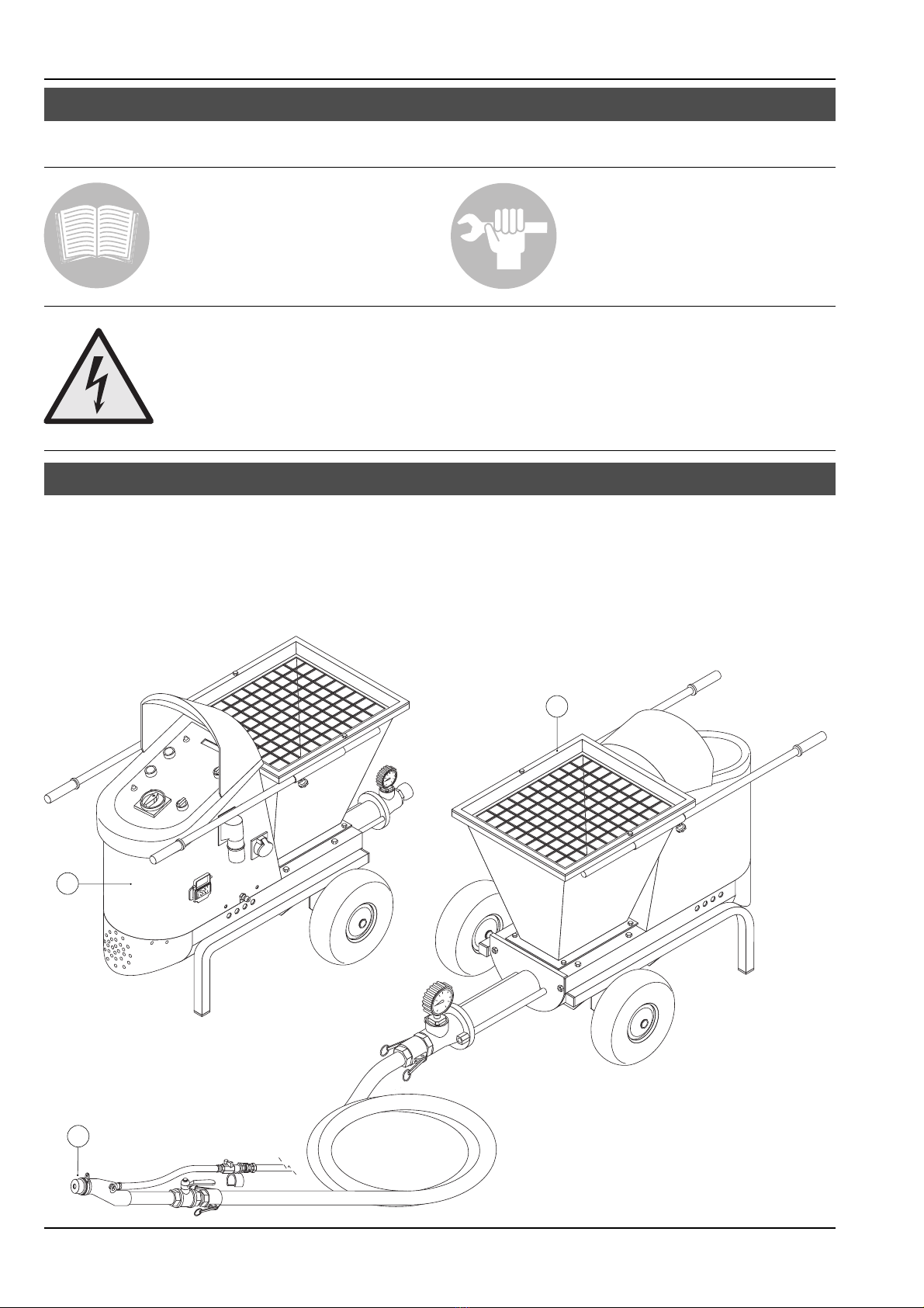
2.2 - Description of the machine 7
2.3 - Size of the machine 8
2.4 - Technical data regarding the machine 8
3. - Transporting the machine 9
3.1 - Transport
4. - Using the machine 9
4.1 - Operating principles 9
4.2 - Pumpable materials 10
Choosing the gun
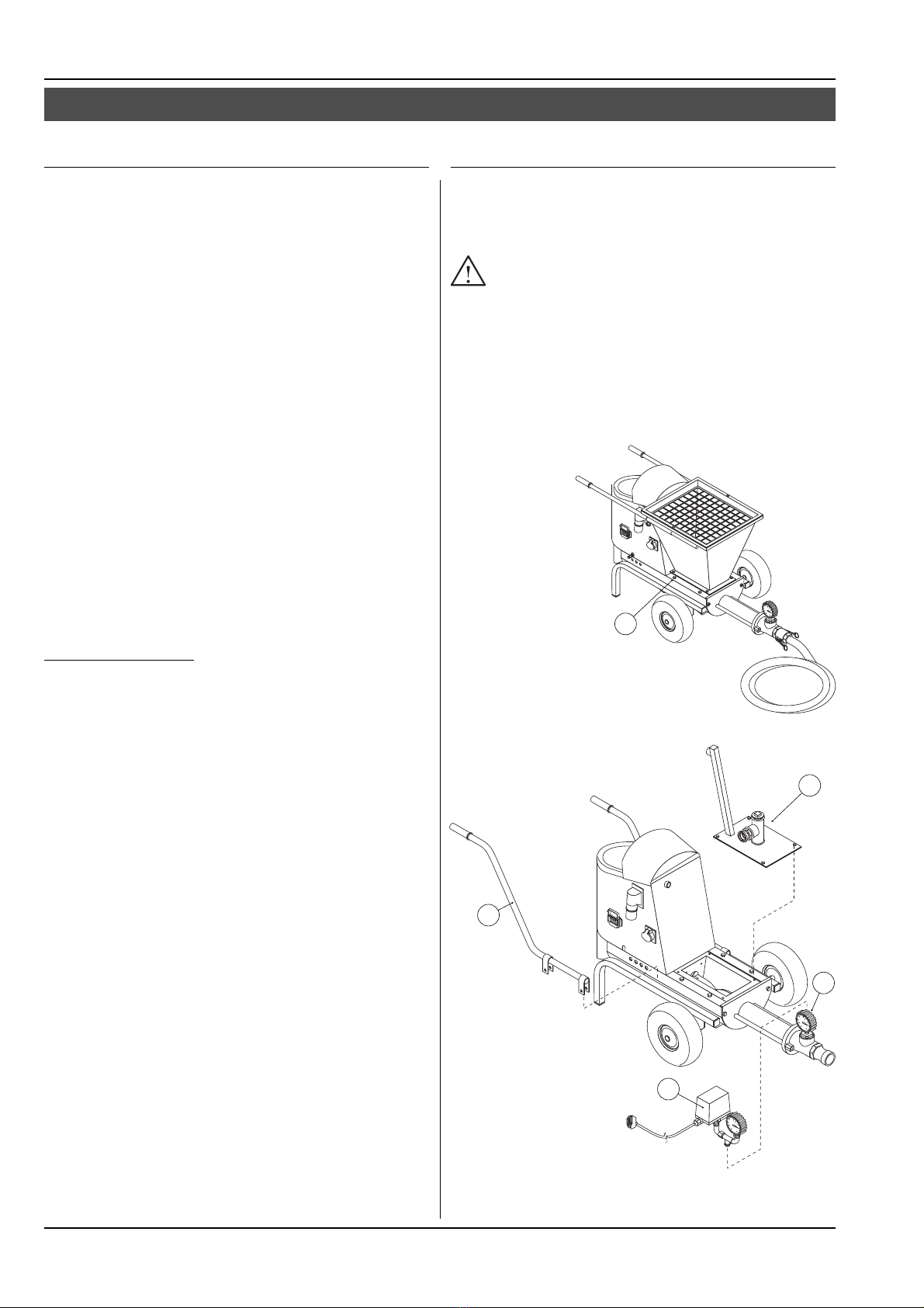
4.2.1 - Conversion kit into admixture dosing pump 10
4.3 - First operations 12
Positioning the machine
Electrical connection
Hoses 13
Couplings
Connections 14
4.4 - Starting the machine 16
Starting the version
4.5 - Washing and stopping the machine 17
4.6 - Pumping group 18
Replacing of the pumping group
5. - Maintenance of the machine 19
5.1 - To be performed by the operator
5.2 - To be performed byauthorized personnel
Operations to be performed every 500 hours
6. - Problems – causes – remedies 20
6.1 - Mortar not flowing from the spray gun 20
6.2 - Operation to be performed by the operator 21
6.3 - Operation to be performed
by authorized personnel
7. - Responsibility of the operator 22
Table 1 - Machine body 24
Table 2 - Transmission - Worm gear pump 26
Table 3 - Switch board - Plugs 28
Table 4 - Remote control 30
Table 5 - Accessory bag DN25 - Hoses DN25 32
Table 6 - Accessory box - cod. 201.131
for ready-mixed plasters 34
DN25 ACCESSORIES
Table 7 - Accessory box- code. 201.136
for skim coats 38
Table 8 - Accessory box
cod. 201.137 e cod. 201.142
for pressure pointing
Delivery tube 40
Table 9 - Injections device 42
Table 9A - Injection pressure shut-down device 44
Table 9B - Pistola iniezioni - Tubazioni 46
Table10 - Pressure gauge – Hoses extensions 48
DN19 ACCESSORIES
Table11 - Accessory bag - Hoses
Pressure gauge 52
Table12 - Accessory box - code 201.116
for ready-mixed plastersi 54
Table13 - Accessory box - code 201.117
for skim coats 56
Table14 - Accessory box
cod. 201.118 e cod. 201.119
for pressure pointing 58
Table15 - Accessory box - cod. 201.120
for finishing coats 60
Table16 - Injections device 62
Table16A - Injection pressure shut-down device 64
ACCESSORI
Table17 - Bag squeezer 68
Table18 - Vibrating Sieve 70
Table19 - Compressor single-phase 170 l/m’ 72
Table20 - Compressor three-phase 592 l/m’ 74
Table21 - Conversion kit into admixture
dosing pump 76
WIRING DIAGRAMM
Table22 - Wiring diagramm 80
USE AND MAINTENANCE SPARE PARTS
CONTENTS

3
MANUALE DI ISTRUZIONE
IMPORTANTE
Read and carefully follow the instructions contained in this
booklet. By doing so, you will thus help prevent accidents,
be fully covered by the manufacturer’s warranty, and have
always available an equipment that is perfectly efficient
and ready to use.
Operation and maintenance of this equipment must be
performed only by skilled personnel who are well aware of
the dangers inherent to the machinery itself.
All standards aimed at the prevention of work accidents
must be rigorously observed, asmust all regulations
covering safety on the jobsite.
The manufacturer shall not be liable in any manner
whatsoever for injury or damage to persons or things
resulting from unauthorized changes in or modification of
this equipment.
CONVEYING AND SPRAYING MACHINE FOR
READY-MIXED MORTARS AND FINISHING COATS
T 7
Machine serial number:
You are strongly advised to enter your machine’s serial
number in the space above which must always be referred
in order to facilitate the work of the personnel in charge,
and itmust likewise be mentioned when requesting service
assistance or spare parts.
We reserve the right to make any technical modification
whatsoever in the interests of improving this machinery,
even if such eventual modifications are not referred to in
this booklet.
Written authorization from Turbosol Produzione SpA must
be obtained for any andall reprinting or reproduction, even
in part, of the information contained in this booklet.

4
It is compulsory to read
the maintenance booklet
prior to operating the machine
SYMBOL KEY
DESCRIPTION
It is compulsory to read
the maintenance booklet
for what regards ordinary
and general maintenance.
Danger:
electrical shock hazard.
BE CAREFUL!
A - Before working, check that the protection grill is well
mounted and fixed on the hopper.
B - The operator must never direct the spray gun towards
other persons.
C - Electric parts, that could be under tension, are present
inside the canopy.
C
B
A

5
The conveying and spraying machine for ready-mixed
mortars and finishing coats model T7 can be supplied in
different versions and with a variety of accessories. As a
result, some of the components described in this booklet
may not be included with your own equipment.
We have taken special care to clearly illustrate the different
variations in order to make it easier for you to select the
use and maintenance instructions applicable to your own
machine.
Please read these instructions carefully prior to turning on
your equipment and follow them carefully.
For whatever other information you might require,
TURBOSOL PRODUZIONE S.P.A.’s customer service is at
your complete service.
TURBOSOL PRODUZIONE S.P.A.
Via Volta, 1
31030 Pero di Breda di Piave (TV) - ITALIA
Tel. 0039 - 0422 - 90.2.51
Fax 0039 - 0422 - 90.44.08
http://www.turbosol.it
e-mail: [email protected]
TURBOSOL Machinery
This machinery is the product of our lengthy experience
and continuous development. The know-how thus
acquired, together with our stringent requirements for high
quality, constitute the basic guarantee for manufacturing
low-wearing machinery which offers total reliability atlow
service costs.
Precautions to take when the machine is operating
Maintenance or repair work must be carried out only when
the machine is turned off. Whatever safety devices that
have been removed in order to complete such work must
be mounted again after maintenance has been carried
out.
Care and maintenance
Care and maintenance are vitally important in making it
possible for the machinery to operate as expected. It is
therefore essential that all maintenance be performed on
schedule and that all required maintenance be carried out
with extreme care.
Safety
This symbol marks every reference to safety in this
booklet, and it must be scrupulously observed.
The personnel in charge must be fully informed about
all safety regulations. Safety andaccident-prevention
regulations currently in effect in your area or country must
likewise be observed.
Training
This symbol indicates that the personnel operating
this machinery must have received special training
in regard to the correct manner in which such operation
must take place.
TURBOSOL SERVICE
For any problem related to trouble with this
machinery or when you need spare parts, contact
your local TURBOSOL dealer.
1.1 - INTRODUCTION
1 - GENERAL INFORMATION
1.2 - GENERAL INFORMATION

6
Location of the Manufacturer’s registration plate
The manufacturer’s registration plate (1) is attached to the
chassis of the machine.
Location of the machine’s serial number
The machine’s serial number (2) is punched on the chassis
as well as on the manufacturer’s registration plate.
2.1 - TYPE OF MACHINE
Manufacturer’s registration plate
The type of machine (A),its serial number (B),and data
on the machine’s operating power are printed on the
manufacturer’s registration plate.
The meaning of the various symbols used is as follows:
(A) = Type of machine: T7
T7 = Worm gear pump for the spraying of
finishing coats, for the pumping and for
stucco.
(B) = Machine serial number: NNNNN/AA
NNNNN = Machine serial number.
/AA = The year of manufacture
2 - DESCRIPTION OF THE MACHINE
E-mail:info@turbosol.it - http://www.turbosol.com/
AB
1
2

7
4
3
6
5
7
8
2.2 - DESCRIPTION OF THE MACHINE
Standard equipment:
•Pump on wheels.
•Stainless steel hopper with cover.
•Electronic output transformer.
•Single-phase electric motor.
•Electric remote control with 33 meter of cable.
•15 meters (10 + 5) of mortar hose Ø 25 x 37 with cam-
lock couplings.
•16 meters of air hose Ø 13 x 19 with quick couplings.
•Bag with usual accessories.
•Accessory box for ready-mixed plasters
•Technical literature.
•The compressor is not included.
Accessories upon request for hoses DN19 and
DN25:
Pressure gauge DN25 and DN19.
Accesory kit for DN19.
Accessory box:
- for ready-mixed DN19
- for finish coats DN19 and DN25
- for pressure pointing without air nozzle DN19 and DN25
- for pressure pointing with air nozzle DN19 and DN25
- for finishing coats DN19.
Delivery tube DN25.
Device for injections at controlled pressure DN19 and
DN25.
Accessories upon request:
Three-phase compressor 592 l/m’ - 3,0 kW - 400 V.
Single-phase compressor 170 l/m’ - 0,75 kW - 230 V.
Bag squeezer.
Vibrating sieve.
Conversion kit into admixture dosing pump.
Control body with 33 meters of cable with output
regulation.
20 metres of electric cable 3 x 4 mm
2with plug and
socket.
Hoses extensions:
10 m of mortar hose complete with couplings Ø 19 x 30
5 m of mortar hose complete with couplings Ø 25 x 37
10 m of mortar hose complete with couplings Ø 25 x 37
10 m of mortar hose complete with couplings Ø 13 x 19
Main components:
The machine is made up primarily of:
a control panel (3),
a gear-box (4),
an hopper (5),
an agitator (6),
a pumping group (7),
a push button electric remote control (8).
a electric remote control with 33 meter of cable (8).

8
N.B.: #The operator must wear acoustic protection earplugs
which guarantee a reduction of al least 20 dB(A).
Version T 7
1.050 mm 640 mm 820 mm 70 kg
2.3 - SIZE OF THE MACHINE
2.4 - TECHNICAL DATA T 7
Here are the machine’s size and its gross weight (ready
for use).
Max. pressure mortar pump 35 bar
Line tension single phase 230 V 10%
Control tension 24 V
Line frequency 60 Hz 1%
Max. currentof circuitbreaker 6kA
Mortar pumpelectricmotor1,5 kW
Absorbedcurrent single phase 230 V 5,2 A
Gearbox oil change (IP DEXRON FLUID II - 0,36 kg) every 1.000 hours
Hopper capacity 50 l
Output 0,5 ÷12 l/m’
Altezza di carico 70 cm
Deliverydistance (approximate) 20 m
Deliveryheight (approximate) 10 m
Deliveryrubber hose for material Ø19 x30
Ø25 x37
Max. pumpable granulometryØ19 x30
Ø25 x37
0÷2mm
0÷5mm
Temperature in the workenvironmentfrom -5° to +35° C
LENGTH WIDTH HEIGHT WEIGHT

9
The T7 ismade up primarily of a hopper with built-
in agitator that receives the mixed material and of a
worm gear pump for conveying that mix to the point of
application. It sprays it on the walls bymeans of a spray
gun (which may differ in nature depending on the type of
material employed). There the mixture combines with air
from an auxiliary compressor.
The pump output is controlled through the two buttons
for the output (9) and (10) which are placed on the control
panel; the output is shown on the display (11).
Turning on and off of the machine is controlled directly by
the spray gun operator through the electric
remote control (12).
Upon request the electric remote control box can be
equipped with output regulation (optional extra): with the
push-button (13) you increase and with the
push-button (14) you decrease
the output.
With the push-button
(15) you start
and stop the
machine.
The machine can be only handly transported.
3.1 - TRANSPORT
3 - TRANSPORTING
4 - USING THE MACHINE
4.1 - OPERATING PRINCIPLES
11
9
10
13
15
14
12

10
The T7 is commonly used for maximum granulometry 5
mm with hoses DN25, and for granulometry 2 mm with
hoses DN19.
Suitable for spraying:
•thin layer coats ;
•finishes;
•orange peel finishes;
•reinforced materials;
•finish coats;
•thermical, acoustic, fireproofing insulations;
•quartz plastic finishes;
•marble coats;
•water-proofs materials;
•protective coats;
•finishing coats;
•adhesive mortars.
For stucco and pressure pointing, for injection of
cementicious slurries at controlled pressure.
Choosing of the gun
The specific gun should be used according to the material
used worked:
DN19
•Gun (code 216.483) for ready-mixed materials
(accessory box code 201.116).
•Gun (code 216.491) for finish coats
(accessory box code 201.117).
•Gun without air nozzle (code 216.493) for pressure
pointing (accessory box code 201.118).
•Gun with air nozzle (code 216.492) for pressure pointing
(accessory box code 201.119).
•Gun (code 216.479) for finishing coats
(accessory box code 201.120).
•Gun (code 216.495) for injections at controlled pressure
(injection device code 216.498).
DN25
•Gun (code 216.241) for ready-mixed materials
(accessory box code 201.132).
•Gun (code 216.266) for finish coats
(accessory box code 201.136).
•Gun without air nozzle (code 216.256) for pressure
pointing (accessory box code 201.137).
•Gun with air nozzle (code 216.496) for pressure pointing
(accessory box code 201.142).
•Gun (code 216.299) for injections at controlled pressure
(injection device code 216.395).
•Delivery tube (code 251.232).
4.2 - PUMPABLE MATERIALS - APPLICATIONS 4.2.1 - CONVERSION KIT into admixture dosing pump
To pump silicate with T7 in conjunction with other machines
such as the POLI T, the PRO H, the TSB 215.
Silicate irritates the eyes and the skin. Use
appropriate protection equipment for your hands
and wear a mask to protect your face.
Handle, in any case, these materials with the
greatest care and stick to the instructions provided
by their manufacturer.
To use the conversion kit into admixture dosing pump itis
necessary to remove the hopper with its cover safety grill
and lifting handles too.
Remove the hopper
by unscrewing
the 4 fixing screws (16).
Secure the silicate cover (17) complete with couplings to
the pump body.
Remove the gauge (18)
fitted onto the delivery
flange.
Connect the pressure
switch group (19) to the
delivery flange.
Secure the lifting handles (20).
16
17
18
19
20

11
Connect the plug box (21) of the pressure switch group to
the plug (22).
Connect the silicate feeding hose to the quick coupling
(23), the other end of the hose must be connected to the
vessel containing the silicate
Make sure that height of suction of the silicate is atleast 50
cm above the coupling (24).
22
21
24
23

12
Positioning the Machine
Place the machine in the most horizontal possible position:
the maximum gradient allowed is 5° both lengthwise and
sidewise.
The machine must be set on the jobsite as close as
possible from the place of application.
Prepare the necessary material for cleaning the machine
(water hose, washing sponges, a.s.o.)
Leave at least 80 cm. of clear space around the
machine and set up a working area free of holes
and dangerously protruding edges..
Electrical connection
Connect the machine to the site electric control panel
or a socket of 16 A bymeans of a neoprene cable
(scratch-resistantrubber)labelled HO7 RN-F and
havinga maximum section:
3 x 4 mm. for distances up to 35 m.
If a cable of inadequate section is used, the machine
does not work properly
The jobsite’s electrical system must have:
•a minimum operating power of 3,3 kW,
•be properly grounded,
•fuses of 16 A (type aM),
•highly sensitive differentials (of 30 mA),
•must meet all the regulations enforced
in the country where the machine is being used.
Connect the machine’s ground terminal to the earth
leakage device by means of a cable having a section equal
to the feeding cable and never lower to 16 mm2.
4.3 - FIRST OPERATIONS

13
Hoses
Lay the hoses down and at the same time check them to
make sure that they are in good conditions.
While pumping isin progress, the first 10 m. of hose will
swing back and forth several centimetres: itisbest to
keep that section of hose raised above the floor in order
to avoid having the hose rubbing on edges or abrasive
surfaces and to prevent fast wear and tear on the hoses
themselves.
Use only those hoses and coupling devices originally
supplied with the machine.
The hoses must be fitted by TURBOSOL
PRODUZIONE S.P.A. or by firms explicitly authorized
by TURBOSOL. In no case whatsoever shall
TURBOSOL PRODUZIONE S.P.A. be held liable for
injury or damage to persons or things resulting from
the use of non-original hoses or coupling devices.
Couplings
Check to be certain that the coupling devices are clean
and in good working order .
•Cam-lock couplings
When you connect the hoses, check that there is the
rubber ring (25),
lock the levers tightly.
Hoses Ø 25 x 37 – length of 15 meters
for a max. pumpable granulometry of 0 - 5 mm.
25

14
Connections
Connect the material hose (26) to the worm gear pump.
Connect the air hose to the auxiliary compressor (27) at
the spray gun.
Then connect the spray gun to the final part of the material
hose (28).
Connect the remote control cable to the machine
connector (29).
The vibrating sieve is not necessary when you use ready-
mixed materials.
The vibrating sieve is necessary with traditional materials
to avoid that aggregates, of non pumpable dimensions,
damage the stator.
Connect the plug of the vibrating sieve to the socket (30).
29
16
28
27
30

15
Various types of spray guns are available depending on the
material sprayed.
Each spray gun is made of:
a coupling to the material delivery hose (31),
a coupling to the air hose (32),
1 air control valve (33),
an air nozzle (34),
with or without possibility of regulation (35)
a deflector (36).
Generally speaking, with deflectors having a smaller
diameter the material is sprayed with a wider pattern and
vice-versa.
31
33
35
32
34
36

16
To start up the machine turn the main switch (39) (red on a
yellow background) clockwise to the I position.
Turn the selector start/stop/reverse (40) on position 1and
check that the machine is pumping normally andmodify
the output according to your necessity through the buttons
that set the output “plus” (41) and “less” (42).
Put the selector (43) on position 2and check that the
rotation direction reverses.
Check that the remote control works properly.
Turn the selector start/stop/reverse (39) and the remote
control selector (44) on position 1andby operating the
remote control, check that the machine starts and stops
normally.
The lamp (45) lights when the inverter interferes to protect
the motor against overload.
If the pilot light (46) is switched on, it shows that the
control panel is energized.
The line socket must always be disconnected when
you operate on the machine and above all on the
electric board.
Before starting the machine, pour some water in the
hopper to avoid that the worm gear runs dry .
Check that the protection grill is well mounted and
fixed on the hopper.
Before turning on the machine, be certain that no
one, except the operators, is standing too close to it.
Be careful: the machine must always run with
material or water in the hopper.
If this is not the case, the pump will wear out
quickly.
Working pressure is indicated by
the gauge (37) positioned in
the pumping group.
The “standard working
pressure” value depends on
the material and hoses used:
it isrecommendable to check
out systematically -on the mortar
hoses pressure gauge- the value indicated in order to
promptly find out any fault.
To ease this procedure, a pressure control device is
available (38) (optional extra) which must be coupled
directly to the gun.
4.4 - OPERATING THE MACHINE
39
43
42
41
44
45
46
37
38

17
If necessary, remove the protection grill (34) in the
hopper, to wash carefully, but before removing the grill,
disconnect the line socket (35) (with main switch on
position 0); then fixit once again correctly,reconnect
the line socket.
Put the cap on the hopper discharge collector and fill the
hopper with water.
Star the machine:
•main switch (39) and selector start/stop/reverse (43) on
position I
•pump water until clean water flows out of the pump.
•Reconnect the hose to the pump .
•Start the machine and pump water until the washing
sponge goes out.
Stop the machine by turning the selector (43) on position
0(stop) and turn the main switch (39) (red on yellow
background) on position 0.
After completing maintenance or repair work, make
sure that all the safety devices have been put back
in place and that no tools have been left inside the
canopy or the hopper.
Once you have pumped your last batch which should be
a little wetter than usual and you begin to see the bottom
of the agitator clearly, stop the pump byusing the selector
start/stop/reverse (43).
Turn the main switch (39) to the 0position.
•Remove the spray gun and wash it carefully, dismantling
the deflector at the same time (36).
•Check to be sure that the nozzle hole (34) is free (if
necessary, clean it ).
•Disconnect the hoses from the
mortar pump hoses and insert
one cleaning sponge into the
hose.
Remove
the discharge
collector cap (47)
on the hopper.
Wash carefully
the hopper with
a stream of water.
Do not direct the water jet onto the control panel or
towards the holes in the lower casing protecting the
electric motor, since it could cause damage to the
actual motor and the electrical equipment inside the
machine.
4.5 - WASHING THE MACHINE AND END OF WORK
48
49
34
36
47

18
4.6 - PUMPING GROUP
Replacing the pumping group
Operate as follows:
Stop the pump, then turn off the motor by using the
main switch (39) before carrying out this operation.
•Raise the protection grill in the hopper;
•Remove the material delivery collector by unscrewing
the braces fixing bolts with the key included in the
equipment.
•Replace the pumping group.
Put the group stator-
worm in a vice, block
the stator, unscrew the rotor
and remove it;
Check to see if the worm
can still be used ( its
diameter must not be more
than 2 mm. smaller than its
original diameter). If this is
not the case, replace the
worm as well as the stator.
To assemble the unit, smear both the worm and the stator
with vaseline (under no circumstances should you use
oil or mineral grease! Such products could cause
irreparable damage to the stator). Then screw the
worm back into the stator. The stator must be mounted
with its countersunk side facing the hopper.
If this procedure makes the re-assembly difficult or even
impossible, pick up the unit with the worm partially inserted
and bang it on the floor several times.

19
Operations to be carried out every 6 months or
every 500 hours
Check:
•The seal of the hopper gaskets.
•The air and material hoses are in good working order.
Listed here below is the essential information
needed for proper maintenance of this machine.
The machine’s operator must read those data before
beginning to operate the machine.
Operations to be carried out daily
•Lubrication
Grease the agitator support in the hopper through the
specific greasing point (50).
In order for this operation to be carried out correctly, the
grease must flow in the hopper.
If you forget to perform this operation, the seals and
supports will be worn out in just a few days’ time.
Read also carefully the instructions booklets about
accessories as compressor, injection group
•Preventive care
Spray demoulding liquid on the hopper.
Check that the seal of the hopper gaskets is good.
5 - MAINTENANCE OF THE MACHINE
5.1 - TO BE PERFORMED BY THE OPERATOR
5.2 - TO BE PERFORMED BYAUTHORIZED PERSONNEL
50

20
6 - PROBLEMS – CAUSES – REMEDIES
6.1 - MORTAR IS NOT FLOWING OUT OF THE SPRAY GUN
The spray gun is blocked
A hardened crust of material, a pebble or a deflector
whose orifice is too small for the material being used may
cause a clogging-up in the spray gun:
•THE MATERIAL DOES NOT FLOW OUT OF THE SPRAY-GUN
In this case:
•Stop the machine by using the main switch.
•Release pressure in the delivery material hoses by turning
the pump reverse for a few seconds.
Release always pressure in the hoses by turning
the pump reverse for a few seconds (5-10) before
disconnecting them.
•Disassemble the deflector and, ifnecessary, the spray
gun so as to remove the cause for clogging.
•Before mounting the deflector and spray gun once again,
be certain that the nozzle is free (and, ifnecessary, clean
it with a piece of wire).
If the mortar is dripping from the spray gun during work,
try to replace the deflector and/or nozzle with one having
a smaller hole
•Start the machine once again and check that the material
flows out normally of the hoses.
Worn out stator
A worn out stator can prevent the material from flowing
out of the gun and mayeven cause blockage due to
overheated material at the beginning of the hose.
It isnecessary to replace the stator and remove the
clogging in case.
Lack of material in the hopper
If, during the work, mortar is flowing in a non-continuous
way, check, at first , that there is material in the hopper.
Mortar hose blocked
A faulty mix or an overly prolonged pause may cause a
clogging up of the material delivery hose:
•material is not flowing out from the spray-gun.
In this case:
•Stop the machine by using the main switch.
•Release pressure in the delivery material hoses by turning
the pump reverse for a few seconds.
Release always pressure in the hoses by turning
the pump reverse for a few seconds (5-10) before
disconnecting them.
Find out just where the mortar delivery line is blocked: the
hose will be hard and stiff at this point.
The worse points are near the couplings.
Disconnect the clogged hose,
hit it with a hammer at the
clogged point so as to break
up the “plug”, andlet the
hardened mix flow out.
•Turn the machine on for several seconds, andmake
certain that the hose has been freed of the “plug”:
the material will flow normally from the hose.
Pour some slurry into the hose before the point where the
blocking occurred (gun direction), connect the hose line
once again, and start over again.
Mortar hose bent
Same as for mortar hose blocking.
Find the bend and straighten the hose.
If the material inside the hopper is not pumpable,
empty the hopper by disconnecting the hose from
the pump and let the material flow out.
Remove, ifnecessary, the discharge cap of the hopper
and wash out all the material with a stream of water.
Prepare the right mix and start again.
Table of contents
Other Turbosol Paint Sprayer manuals
Popular Paint Sprayer manuals by other brands

Graco
Graco VIBRA-FLO 17P002 Operation, parts

Pattfield
Pattfield PE-500 SP manual

Titan
Titan Maxum Elite operating manual

CLAS
CLAS OP 1335 manual

Task Force Tips
Task Force Tips VIT Instructions for installation, safe operation and maintenance

WAGNER
WAGNER 2371053 Translation of the original operating instructions