Turbosol UNI 30 D Specification sheet

ITALIANO
PUMPING SYSTEMS FOR THE BUILDIN G I NDUSTRY
ENGLISH
Serial number
CT. 200.359
ISTRUCTIONS FOR USE AND MAINTENANCE
COMPREHENSIVE CATALOGUE & SPARE PARTS

23
1 - Use and maintenance 5
1.1 - Introduction 5
1.2 - General information 5
2 - Symbol key 6
3 - Caution and other hazards 7
3.1 - Caution and other hazards 7
4 - Description of the machine 8
4.1 - Type of the machine 8
Manufacturer’s registration plate 8
Manufacturer’s registration plate location 8
Machine’s serial number location 8
4.2 - Description of the machine 9
4.3 - Size of the machine 10
4.4 - Technical data 10
5 - Trasport 11
5.1 - Hoisting 11
6 - Use of the machine 12
6.1 - Operating principles 12
6.2 - Pumpable materials 13
6.3 - Preliminary operations 14
Positioning of the machine 14
Hoses 14
Anchoring the hoses 14
Couplings 15
Connections 15
6.4 - Starting the machine 16
Preliminary controls 16
Starting up 18
6.5 - Washing and stopping the machine 20
Stopping the machine 20
Cleaning 20
7 - Maintenance of the machine 22
7.1 - To be performed by the operator 22
Operations to be perfomed daily 22
At start 22
At the end of the working day 23
Every week 23
Machine not at work for long time 24
7.2 - Change of wear and tear parts by qualified
personnel 25
Change of the worn ball valves 25
Replace the gaskets of the inspection plugs 25
Changing the damaged valve’s seats 26
Change of the worn piston 26
Change of the teethed wheel
and the rubber ring of the centrifugal joint 27
7.3 - To be performed by qualified personnel 27
Operations to be performed every year or 100 h 27
Operations to be performed every 200 h 27
Operations to be performed every 6 m or 500 h 27
8 - Trouble shooting 28
8.1 - Mortar does not come out of the gun 28
Blockage of the spraygun. 28
Blockage of the mortar hoses. 28
Blockage of the valve’s group. 29
8.2 - Other inconvenients 29
Loose belt 29
8.3 - Works to be performed by the operator 30
8.4 - Works to be performed by the qualified
personnel 33
9 - Responsability of the operator 34
Tav. 1 - Chassis 36
Tav. 2 - Pump group 38
Tav. 3 - Gearbox group 42
Tav. 4 - Agitator 44
Tav. 5 - -Air system 46
Tav. 6 - Engine 48
Tav. 7 - Compressor 52
Tav. 8 - Mixer 54
Tav. 9 -Towbar - axle 58
Tav. 10 - Tool box cod. 201.145 60
Tav. 10 - Tool box cod. 201.145 62
Tav. 11 - Hoses 64
USE AND MAINTENANCE SPARE PARTS
INDEX

23
IMPORTANT
Read and carefully follow the instructions contained in
this booklet. You will thus help prevent accidents, be fully
covered by the manufacturer’s warranty, and will always
have available an equipment that is perfectly efficient
and ready to use.
Operations and maintenance of this equipment must be
performed only by skilled personnel who are well aware
of the dangers inherent to the machinery itself.
You must follow the regulations concerning the prevention
of work accidents as well current laws regarding safety in
the work place.
The manufacturer shall not be liable in any manner
whatsoever for injury or damage to persons and things,
resulting from unauthorized changes or modifications of
this equipment.
MACHINE FOR CONVEYING AND SPRAYING
TRADITIONAL, STRUCTURAL AND SPECIAL
MORTARS
UNI 30 D
The unit’s serial number:
You are strongly advised to enter your equipment’s
serial number in the space above, which must always be
referred to in order to facilitate the work of the personnel
in charge, and it must likewise be mentioned when
requesting service assistance or spare parts.
We reserve the right to make whatsoever technical
modifications in the interests of improving this
machinery, even if such modifications are not mentioned
in this booklet.
Written authorization from Turbosol must be obtained for
any and all full or partially reprinting or reproduction, of
the information contained in this booklet.
INSTRUCTIONS FOR USE AND MAINTENANCE

4
5

4
5
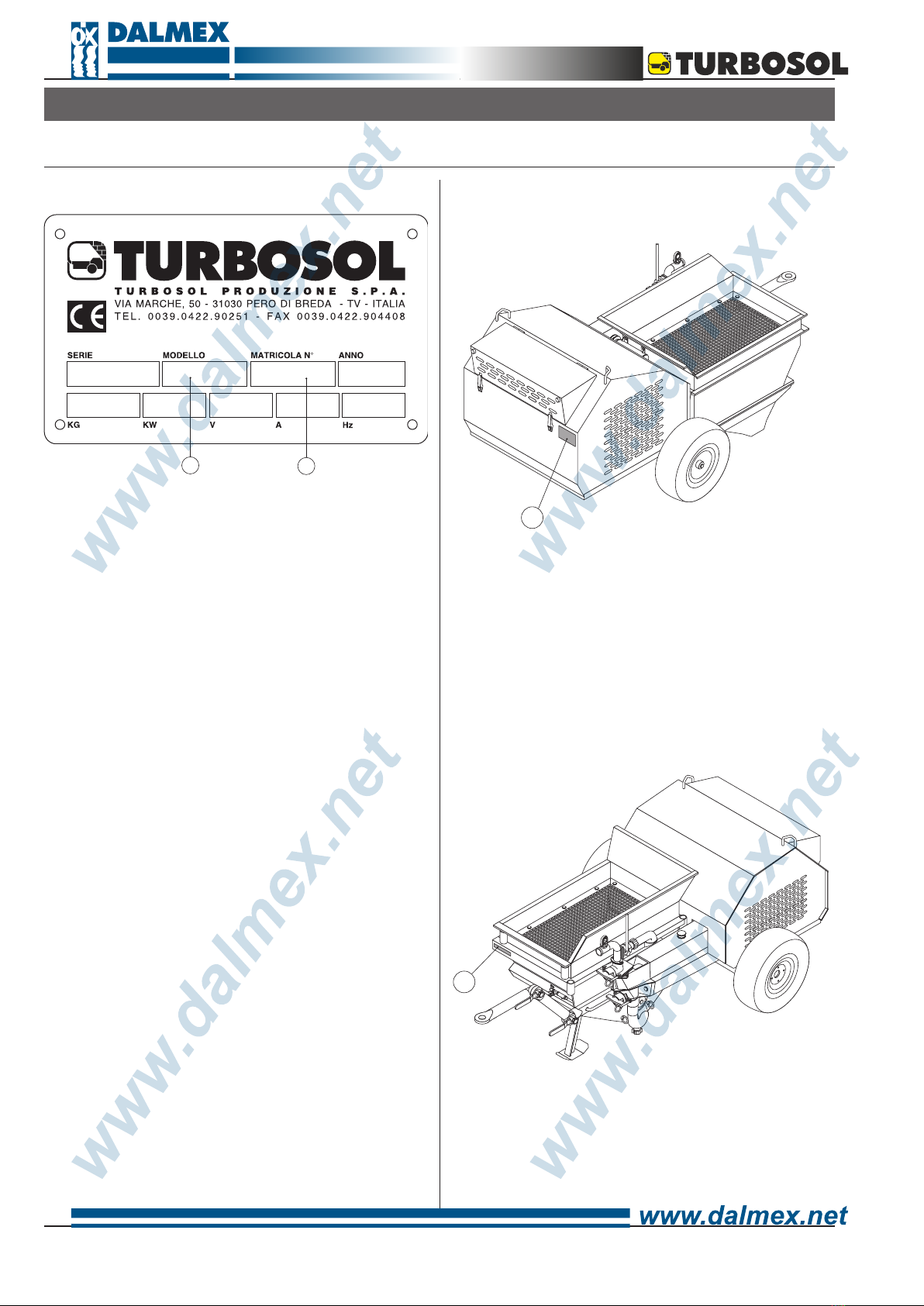
The UNI 30 mortar conveyor and sprayer machine can
be supplied with a variety of accessories. As a result,
some of the components and spare parts described
in this booklet may not be included with your own
equipment.
We have taken special care to clearly illustrate the
different variations in order to make it easier for you
to distinguish the use and maintenance instructions
applicable to your own machine.
Please read these instructions prior to starting up your
equipment and follow the instructions carefully.
For any other information you might require, TURBOSOL
PRODUZIONE S.P.A.’s customer service is at your
complete disposal.
TURBOSOL PRODUZIONE S.P.A.
Via Volta, 1
31030 Pero di Breda di Piave (TV) - ITALIA
Tel. 0039 - 0422 - 90.2.51
Fax 0039 - 0422 - 90.44.08
http://www.turbosol.it
e-mail: [email protected]
TURBOSOL Machinery
This machinery is the product of our lengthy experience
and continuous development. The know-how thus
acquired, together with our stringent requirements
for high quality, constitutes the basic guarantee for
manufacturing low-wearing machinery which offers total
reliability at low servicing costs.
Precautions to be taken when the machine is operating
Maintenance or repair works must be carried out only
when the machine is turned off. Whatever safety devices
have been removed in order to complete such work, they
must be mounted again after maintenance has been
carried out.
Care and maintenance
Care and maintenance are vitally important in making it
possible for the machinery to operate as expected. It is
therefore essential that all maintenance will be performed
on schedule and will be carried out with extreme care.
Safety
This symbol marks each reference to safety in
this booklet, and it must be scrupulously observed.
The personnel in charge must be fully informed about
any safety regulations. Safety and accident-prevention
regulations currently in effect in your area or country
must likewise be observerd.
Training
This symbol indicates that the personnel operating
this machinery must have received special training in
regard to the correct manner in which such operation
must take place.
TURBOSOL SERVICE
For any problem related to trouble with this machinery or
when you need spare parts, contact your local Turbosol
dealer.
1.1 - INTRODUCTION 1.2 - GENERAL INFORMATION
1 - GENERAL INFORMATIONS

6
7
Warning:
machinery in operation
2 - SYMBOL KEY
PROHIBITION
It is compulsory to read this
maintenance booklet prior
to operating the machine
OBLIGATION
It is compulsory to read this
maintenance booklet with regard to
regular and general maintenance
Lifting point It is compulsory to grease the
indicated point

6
7
AB
D
H
G
F
B
H
I
I
C
E
A - Operate the unit only with the bonnet properly
closed.
B - Operate the unit only with the vibrating sieve proper-
ly positioned.
C - Check that the grill on the hopper is properly fixed.
For no reason the machine has to work without this
safety device.
D - The mixer is fixed with safety grill on top.
The opening of the above mentioned grill will
determine the immediate block of the mixer.
E - The machine must never pump material when not
connected to the hoses and to the spray gun.
F - Warning, check that no one is standing too close to
the air group valve.
G - The spray gun should not be directed towards
people. In case of blockage of the gun, no one
should look directly into the hose of the deflector.
The sudden exit of the blocked part or of mortar
under pressure, may cause problems to the sight.
H - Moving parts and hot parts are present inside the
canopy as well as battery acids.
I - Do not remove any protection.
L - Before disconnectiong the material hose couplings
or the spraygun, make sure that the pressure on
the pressure gauge is equal to 0 (zero) and that no
pressure is still present in the hoses.
M - Use gloves in nitrile for protection against cuts
and abrasions, preferably models with CE 940072
certificate and googles that can provide a total
protection to the eyes, with infrangible and
anti-fogging lenses (in policarbonate and vinyl
chloride).
3 - CAUTION AND OTHER HAZARDS
3.1 - CAUTION AND OTHER HAZARDS
L

8
9
Manufacturer’s registration plate location
The manufacturer’s registration plate (1) is attached to
the chassis of the machine.
Machine’s serial number location
The machine’s serial number (2) is printed on the chassis
as well as on the manufacturer’s registration plate.
4.1 - TYPE OF MACHINE
Manufacturer’s registration plate
The type of machine (A), its serial number (B), and
data on machine operating power are printed on the
manufacturer’s registration plate.
The meaning of the various symbols used is as follows.
(A) = Type of machine: UNI 30 D (S) (MF)
UNI 30 D = Machine with piston pump
for pumping, conveying and spraying
traditional, structural, and special
mortars.
S = Standard version.
MF = Version with fixed mixer.
(B) = Machine’s serial number: NNNNNN/AA
NNNNNN = The unit serial number.
/AA = Year of manufacture.
E-mail:[email protected] - http://www.turbosol.com/
AB
1
4 - DESCRIPTION OF THE MACHINE
2

8
9
7
8
5
9
6
3
4.2 - DESCRIPTION OF THE MACHINE
Standard equipment:
• Protection frame for mechanical parts.
• Self-bearing frame with pneumatic wheels and
articulated draw-bar.
• Vibrating sieve with 8 mm mesh.
• Switch board built in accordance to EC norms.
•Piston pump with gravity ball valves.
•Mechanical gearbox with 2 speeds.
•Automatic mechanical safety device against
overpressure.
•Material recycling device
•Built-in air compressor of 270 l/m’ output.
•Positive action mixer of 180 l. (version MF).
•40 m (20+10 Ø 50 +10 Ø 40) of mortar rubber hoses
with cam-lock couplings.
•41 m (31 + 10) of air hose Ø 13 with quick couplings.
• Accessory box with spray gun and a series of nozzles.
• Technical literature.
Accessories upon request:
On line pressure gauge for hoses Ø 50.
Pumping nozzle for hoses Ø 40.
Pumping nozzle for hoses Ø 50.
Cement slurry injection device.
Hose extensions:
- Hose extensions of 10 m mortar/air (Ø 50 x 66 e Ø 13 x
19).
- Hose extensions of 20 m mortar/air (Ø 50 x 66 e Ø 13 x
19).
Main components:
The machine is made up primarily of:
a hopper (3) an agitator (4),
a piston pump group (5),
a diesel engine (6) that operates a gearbox (7) with 2
speeds (7a) a safety device (7b) against overpressure,
a compressor (8),
a vibrating sieve (9) operated by a mechanical gear-
box (10) and for the MF version: a fixed mixer (11).
4
11
9
10
ROD ENGINE STOP
7a
7b
BY-PASS LEVER
MUSHROOM SHAPED LID
FOR CYLINDER
SUCTION COLLECTOR
INSPECTION PLUG FOR THE
SUCTION VALVE
INSPECTION PLUG FOR THE
DELIVERY VALVE
DELIVERY OUTLET WITH
PRESSURE GAUGE

10
11
4.3 - SIZE OF THE MACHINE
LENGTH WIDTH HEIGHT WEIGHT
2150 mm 1500 mm 110 mm 810 kg
LENGTH WIDTH HEIGHT WEIGHT
2150 mm 1500 mm 1600 mm 1020 kg
Version DS Version DMF
4.4 - TECHNICAL DATA
Mortar pump pressure (indicative) 30 bar
Auxiliary circuits voltage 12 V
Engine power 14 kW
R.P.M. max 2.600 R.P.M.
min 1.200 R.P.M.
Pilot valve fixed pressure max 4,5 bar
Compressor relief valve fixed pressure 6,5 bar
Compressor maximum valve pressure 6,5 bar
Compressor oil change (SHELL RIMULA EXTRA D 15W40) every 100 hours
Gearbox oil change (ELF POLYTELIS 100) every 500 hours
Engine oil change (diesel engine oil 15W40) check engine book
Mixer gearbox oil change (ELF Reductelf SP220) every 500 hours
Hopper capacity 200 l
Mixer capacity 180 l
Delivery distance (indicative) 200* m
Delivery height (indicative) 60* m
Delivery hoses
1° Part special Ø 50 x 69** mm
Extensions normal Ø 50 x 66 mm
Final Ø 40 x 53 mm
Maximum pumpable granulometry 8 mm
Temperature in the work environment from 5° to + 40° C
Sound power level (84/533/EEC) <100 dB(A)
N.B.: * Maximum distance and height cannot be reached at the same time.
** Use only hoses made specially for this machine.
For other data regarding the diesel engine please refer also to the attached engine booklet.
Here are the size of the machine and its gross weight (ready for use).

10
11
5 - TRANSPORT
5.1 - HOISTING
In order to lift the machine hook the cables up to the
handles (12) of the bonnet (make sure first that the
hooks are closed) and to the tow bar (13).
• Make sure that the safety screw
(14) that blocks the bonnet is
correctly fixed.
Avoid hoisting the machine with a fork-lift.
Minimum length of the ropes:
- 1,00 m. for the ropes to be connected to the handles.
- 1,30 m. for the ropes to be connected to the tow bar.
12
13
Use only hoisting equipment, hooks and ropes that have
been tested and approved for lifting at least 1000 kg.
Before lifting up the machine, make sure that no one is
standing too close to it.
The mortar mixed separately with whatever kind
of mixer or prepared with the built-in mixer (MF
version), will be discharged on the vibrating sieve of the
machine.
14
13
12
12

12
13
6 - USE OF THE MACHINE
6.1 - OPERATING PRINCIPLES
The sieved mortar falls into the hopper. From here it is
pumped by means of a gravity ball valve pump up to the
place where it is need through rubber hoses and sprayed
with a spraygun (or various type depending of the ma-
terials used) where material is finally pushed by the air
coming from the built-in the machine.
The start and stop of the machine are controlled directly
by the operator at the spraygun, opening and closing the
air cock of the gun itself (15).
Every spraygun is made of:
a material coupling (16),
an air coupling (17),
an air cock (15),
an air nozzle (18),
a deflector (19).
Generally with smaller size deflectors material is sprayed
with a wider spray pattern and vice versa.
Through the by-pass lever (20) it is possible to pump the
material into the hoses (horizontal position) or to recycle
it into the hopper (vertical position).
Therefore it is possible to start the unit without load, or
in case of a blockage in the
hoses or in the spraygun, to
discharge the pressure pre-
sent in the hoses (vertical
postion).
The safety device, a tor-
que limiter, disengage the
trasmission between the en-
gine and the pumping group
in order to avoid dangerous
overpressures on the hoses
and on the pumping group.
15
20
16
15
17
18
19

12
13
Please find some basic concepts on how to make a
pumpable mix-design for the UNI 30:
• the aggregates must have a good proportional
gradient on the granulometric curve: mixed sand
with a grain size of 0-6 mm;
• There must be a sufficient amount of binding agent
(about 350-400 kg/mc) and the proportions must be as
follows:
2/3 hydraulic lime, 1/3 slaked lime;
1/3 hydraulic lime, 2/3 slaked lime;
1/3 cement, 2/3 slaked lime;
2/3 cement, 1/3 slaked lime.
• Do not use plasticized (aerated) lime and, whatever
the case, not in a percentage greater than one -third of
the binding agent. Otherwise the machine’s output will
decline noticeably.
• The mix must have a plastic consistency (i.e. neither
too dry nor too wet).
6.2 - PUMPABLE MATERIALS
% Material left on the sieve
% Material gone throug the sieve

14
15
6.3 - PRELIMINARY OPERATIONS
Positioning of the machine
Place the machine in the most horizontal possible
position: the maximun gradient allowed is 5° both
lengthwise and sidewise.
The machine must be placed at that point on the jobsite
where you can take best advantage of the hoses
operating range.
Leave at least 80 cm. of clear space around the
machine and set up a working area free of hoses
and dangerously protruding edges.
Make sure that the bonnet
is tightly closed with the
safety screw (14).
After completing maintenance or repair work,
make sure that all the safety devices have been
put back in place and that no tools have been left
inside the canopy, the mixer or the hopper.
Hoses
Lay the hoses down and at the same time check them to
make sure they are in good conditions.
While pumping is in progress, the first 10 m of hose will
swing back and forth some centimetres. It is better to
keep that section of hose raised above the floor in order
to avoid the rubbing of the hose on edges or abrasive
surfaces and not to increase the wear and tear on the
hoses themselves.
The following hoses have to be used:
• for the first 20 m special hose Ø 50 x 69 mm.
• for the extension standard hoses Ø 50 x 66 mm.
• terminal of 10 m Ø 40 x 53 mm.
Use always the complete hose length (20 + 10 + 10)
even if exceeding the working needs.
Shorter hose lengths will cause discontinuous spraying.
Use only original hoses and couplings.
The connection between hoses and couplings
must be done by TURBOSOL PRODUZIONE
S.P.A. or by companies directly authorized.
For no reason TURBOSOL PRODUZIONE S.P.A.
shall be liable for whatsoever injury or damage to
persons and things resulting from the use of non-
original hoses and couplings.
Use only hoses supplied by TURBOSOL
PRODUZIONE S.P.A., specific for this type of machine.
With non-original hoses the unit will not perform
correctly.
Anchoring the hoses
The hose line must be properly anchored: use the hoses-
belts which are supplied with the machine to anchor the
vertical parts and eventually the appropiate hose-bend at
the floor.
Make sure that the
air hose is not bent
at anchoring point.
The before mentio-
ned hose has to be
anchored separa-
tely from the mortar
hose.
Make sure that the
coupling of the mor-
tar and air hose
are locked tightly.
14

14
15
Make sure that the mortar hoses are correctly anchored
at the building in order to avoid dangerous shaking due
to the strokes.
Couplings
Check that couplings are clean and in good working
conditions.
• Cam-lock couplings
When you connect the hoses, check that there is the
rubber gasket (21),
lock the levers of the cam-lock coupling tightly;
21
The longer hoses (20 m) are always connected together
to the machine and then the shorter hoses until the
connection to the gun.
Connections
Connect the mortar hoses to the pump group (22) and
the air hose to the quick coupling of the air group (23).
Then connect the spraygun to the final material hose
(24), and to the air hose (25), locking the couplings
tightly.
In the version with mixer (MF) connect the water hose to
the rubber holder (26).
23
22 25
24
26

16
17
6.4 - STARTING THE MACHINE
Preliminary controls
Make the following checking:
• Compressor oil level:
The level must be on MAX notch printed on the dip
stick.
Eventually add some oil with SHELL RIMULA EXTRA
D 15W40
• Gearbox oil level:
Check the level observatory (27) and
eventually add (28) oil - ELF Polytelis
100
• Engine oil level:
Remove the dip stick
(29) and check that the
level is close to maximum.
Eventually add (30) diesel
engine oil 15W40
• Diesel level:
Remove the tank tap (31),
pour in clean diesel and
close tightly.
• Lubrication water
Check that piston by lubrication tank is full with water.
Restore the level adding clean water in the proper
opening (32) situated on top of the cylinder.
In winter add anti-freeze in order to avoid the forming
of ice or discharge the
water whenever the ma-
chine is not working.
In any case, the water has
to be changed every 5
working days.
• Gear lever
Check that the gear lever (33) is placed in even position
(the machine features a gearbox with 2 speeds).
• Grill on hopper
Check that the grill on
the hopper is properly
fixed.
For no reason what-
soever the machine
has to work without
this safety device.
• Safety screw
28
27
29
30
31
32
33

16
17
Check that the safety screw (14) that blocks the
bonnet is properly fixed.
• Inspection plugs
Make sure that the inspection plugs (34) on the ma-
chine are tightly closed.
Make sure to use the proper key supplied w i t h
the machine (35) in order to
close the ring nuts tightly.
Version with mixer (MF version)
• Grill on mixer
Check that the grill on the mixer
is properly positioned.
While lifting the grill on the mixer, the machine stops
automatically. This is due to a device that switches off
the diesel engine.
In order to start the ma-
chine again set back the
grill in the right position
and start again the en-
gine.
• Control lever
Stop the motion of the
mixer using the indicated
control lever (36).
After eventual repair or
maintenance works make
sure that all the safety
devices are mounted
back and that no tool
is left inside the engine
compartment or the material hopper.
14
Tools or wipers left in the engine compartment may as
well cause the brake down of the cooling fan.
Before starting the machine,
prepare the desired mix in
a site or built-in mixer and
separately prepare 15 ÷ 20
liters of slurry (50% water
+ 50% cement or hydrated
lime) and pour it into the
hopper.
Before starting the machine make sure that no one
apart from the authorized personnel is standing
close to it.
Use gloves in nitrile for protection against cuts and
abrasions, preferably models with CE 940072 certificate
and googles that can provide a total protection to
the eyes, with infrangible and anti-fogging lenses (in
policarbonate, and vinyl chloride).
Starting up
Check that the air delivery cock (37) is open, that the
discharge cock (38) is closed and that the air cock to the
gun (15) is open.
34
35
36

18
19
When the engine has warmed up for some minutes,
switch it off pulling the indicated head (40).
Set the gear lever (33) in position
1 or 2.
Start again
the engine.
Make sure that the machine works correctly:
• Open and
close two
or three
times the
delivery
air cock
(37), to
make
sure
that the
pneuma-
tic remote control works properly. The engine goes
to a minimum re-
volution and the
centrifuge joint cuts
the transmission to
the pumping group.
Start the machine
opening the delivery
air cock (37): the pump starts to push the slurry previou-
sly poured in the hopper.
With the by-pass lever (20) always in vertical position
(recycle of material into the hopper), check that the pump
is engaged.
If this does not happen switch off the machine
Make sure that the by-pass lever (20) is in vertical
position (recycle of material into the hopper).
Caution: the machine must always work with
material or water in the hopper.
Failing to do so the wear and tear of the piston will
increase dramatically.
In order to start the engine turn the key (39) in
position 1.
As soon as the engine has started close the air delivery
cock (37): the machine engine will set at minimum rpm.
38
37
15
37
20
40
39
33

18
19
open the tie-rod, remove the inspec-
tion plugs of the delivery valve
(41), remove the rubber
ball valve (42), and pour
some slurry in the valve
body (43).
Then place back the ball
valve and the inspection
plug, finally close tight the
tie-rod and start again.
Put the by-pass lever (20)
in horizontal position: the
machine starts to pump
slurry into the hoses.
Before the slurry is over
pour some prepared
mortar from the mixer to
the vibrating sieve. (S version)
Version with fixed mixer (MF)
Activate the mixer using the control lever (36) and
prepare the mortar.
Load the mixer with sand, cement/
lime and water.
Discharge the mix
on the vibrating
sieve opening the
discharge door with the indicated
lever (44).
The slurry starts coming out of the
spraygun and soonafter the mortar will follow.
Now the machine is in working conditions and can be
stopped using the air cock on the spraygun (15).
Usually, when the machine is
on stand-by, the operator
has to move the by-pass
lever (20) in recycling position (vertical).
At the next start up the before mentioned lever has to be
placed in pumping position (horizontal).
In case of long stops, open the discharge cock (38) and
place the by-pass lever in vertical position so that
the mortar can be recycled into the hopper.
Make sure that the mortar in the hopper is always
at such a level to cover the agitator. If the level is not
sufficient the pumping piston (rubber) will suffer a very
fast wear and tear due to the lack of lubrication.
The operator on the spraygun does not have to point the
spraygun towards other people.
During pumping operations the operator at the machine
should check that the
pressure gauge (45)
(positioned on top of the
pumping group) never
exceeds 20 ÷ 25 bar.
A higher pressure may
indicate a blockage in the
mortar hoses or in the
spraygun. If this happens,
stop the machine and
discharge the pressure in
the hoses turning the by-
pass lever (20) in vertical
position then remove the
blockage (page 28).
In case of blockage of the spraygun, for no reason
whatsoever you should look directly in the hole of
the deflector. The sudden exit of the blocked part
or of mortar under pressure may cause problems
to the sight.
20
36
44
20
38
15
45
42
41
43

20
21
During all these operations the air cocks must
remain completely closed or open. The partial
opening will cause the stop of the machine.
In the event of an overpressure in the pumping pressure
the safety device will intervene inside the gearbox.
Take the by-pass lever (20) in recycle position (vertical)
and verify that the pressure gauge (45) shows a pressure
of 0 (zero) bar.
Stop the machine (move the key to position 0), remove
the cause of the blockage (improper mix, blockage of
the hoses or of the spraygun), and then insert again the
safety device using the proper lever (46).
Stopping the machine
While pumping the last mix, which should be more fluid,
the machine should be stopped only when the agitator
can be seen in the hopper.
At this stage close the de-
livery air cock, move the
by-pass lever to a vertical
position (20) and make
sure that the pressure
gauge (45) shows 0 bar.
Switch off the engine by
pulling the indicated head
(40) then turn the key (39)
to position 0.
Before opening a coupling of the
mortar hose or disconnecting
the spraygun, make sure that
the pressure gauge indicates a
pressure of
0 (zero) bar
and that no
pressure is
remaining in
the hoses.
The operator must be properly trained in order
to perform this operation.
Before opening any couplings, make sure that there is no
remaining pressure in the hoses and that people are not
standing close to the machine.
Only trained people can carry out the above
procedure, which may be dangerous at times.
Cleaning
• Remove the spraygun and wash it carefully, taking the
deflector apart (19).
• Make sure that the hose on the nozzle (18) is free (if
necessary clean it)
46 40
39
20
45
6.5 - WASHING AND STOPPING THE MACHINE
18 19
Table of contents
Other Turbosol Paint Sprayer manuals
Popular Paint Sprayer manuals by other brands

Graco
Graco VIBRA-FLO 17P002 Operation, parts

Pattfield
Pattfield PE-500 SP manual

Titan
Titan Maxum Elite operating manual

CLAS
CLAS OP 1335 manual

Task Force Tips
Task Force Tips VIT Instructions for installation, safe operation and maintenance

WAGNER
WAGNER 2371053 Translation of the original operating instructions