turck TW-R10-M-B146 User manual

Your Global Automation Partner
Operating Instructions
TW-R…-M-B146
RFID Tags with a Password
Function

2
Hans Turck GmbH & Co. KG | T +49 208 4952-0 | F +49 208 4952-264 | [email protected] | www.turck.com
Contents

3
2018/04
1 About These Instructions 5
1.1 Target groups 5
1.2 Explanation of symbols 5
1.3 Other documents 5
1.4 Naming convention 5
1.5 Feedback about these instructions 6
2 Notes on the Product 6
2.1 Product identication 6
2.2 Scope of delivery 6
2.3 Legal requirements 6
2.4 Manufacturer and service 6
3 For Your Safety 7
3.1 Intended use 7
3.2 Obvious misuse 7
3.3 General safety notes 7
4 Product Description 8
4.1 Device overview 8
4.2 Properties and features 8
4.3 Operating principle 9
4.4 Functions and operating modes 9
4.5 Technical accessories 9
5 Mounting 10
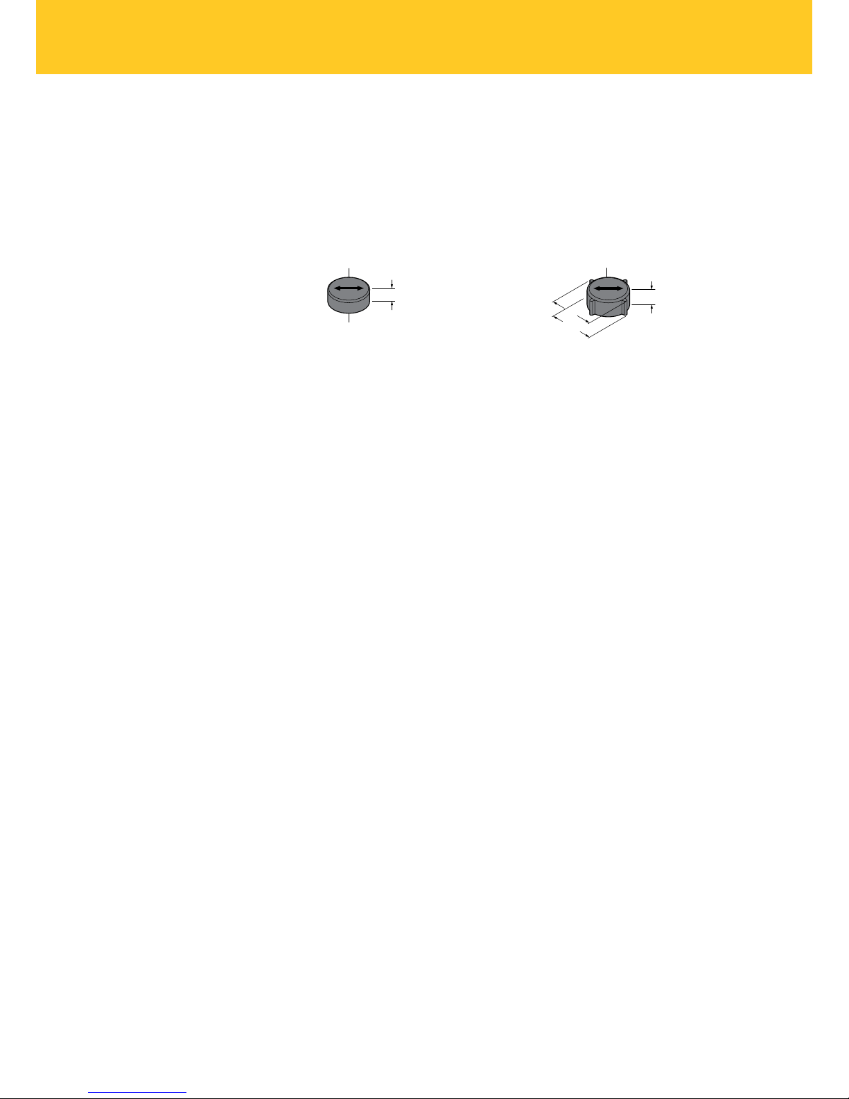
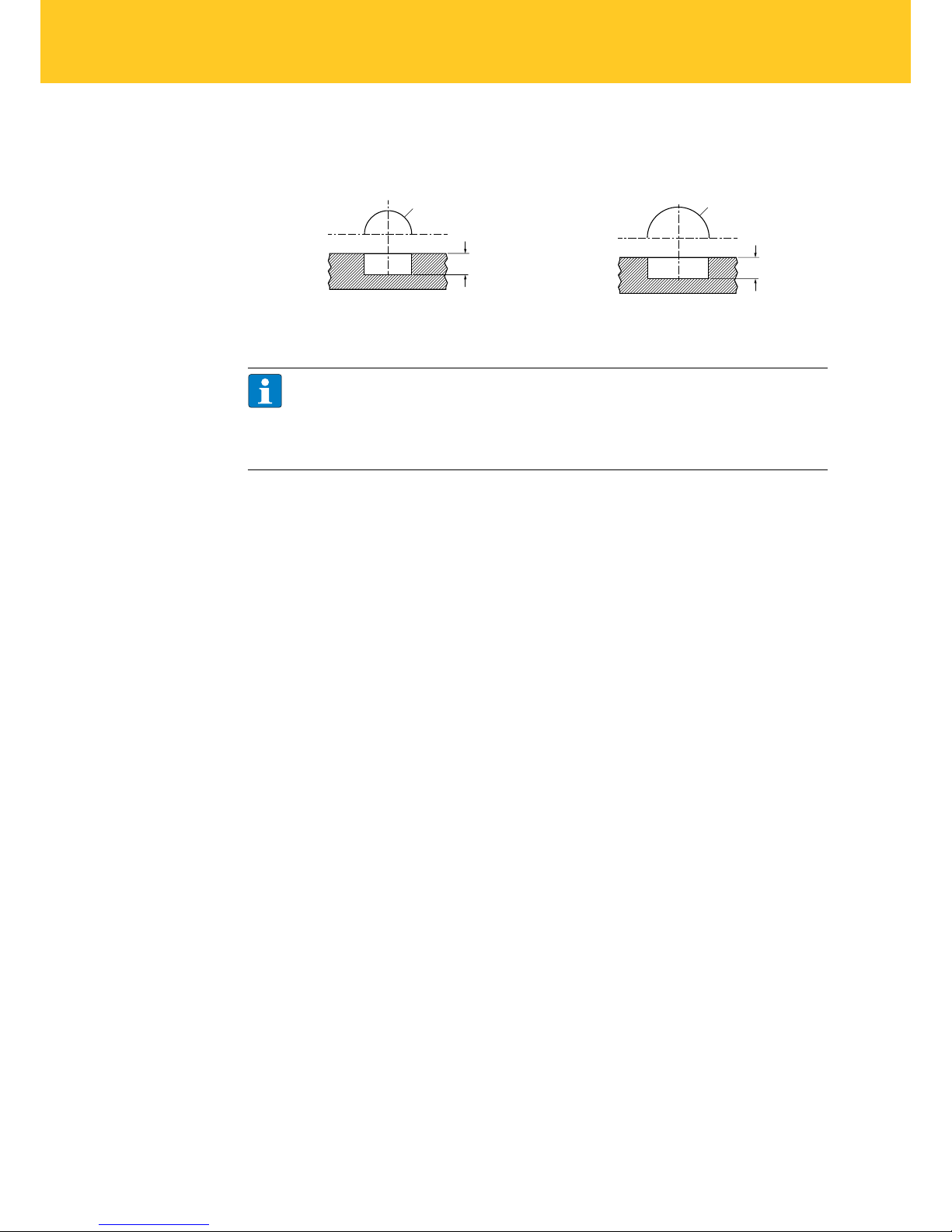
5.1 Aligning tags to the read/write head 10
5.2 Fastening tags to the object 11
6 Operation 12
7 Setting – Protecting Tags with a Password 12
7.1 Component and rmware version 12
7.2 BLxx-2RFID-A module – Overview of commands 14
7.2.1 Set Transceiver PWD command 14
7.2.2 Set Tag PWD command 16
7.2.3 Set Tag Protection command 18
7.2.4 Get Tag Protection Status command 20
7.2.5 Resetting the password in the read/write head 21
7.3 BLxx-2RFID-S module – Overview of commands 22
7.3.1 BLxx-2RFID-S module – Process output data 22
7.3.2 Set Transceiver PWD command 23
7.3.3 Set Tag PWD command 25
7.3.4 Set Tag Protection command 27
7.3.5 Get Tag Protection Status command 29
7.3.6 Resetting the password in the read/write head 31
7.4 Setting password protection for tags 32
7.4.1 Multiple tags with the same password in an application (example) 32
7.4.2 Multiple tags with dierent passwords in an application (example) 33
Contents

4
Hans Turck GmbH & Co. KG | T +49 208 4952-0 | F +49 208 4952-264 | [email protected] | www.turck.com
7.4.3 Setting password protection via FDT/DTM 35
7.5 Addressing password protected areas of a tag 39
8 Troubleshooting 40
9 Maintenance 40
10 Repair 40
10.1 Returning devices 40
11 Disposal 40
12 Technical Data 41
13 Appendix: EU conformity declaration 42

5
2018/04
1 About These Instructions
These instructions describe the setup, the functions and use of the product and help you to op-
erate the product for its intended use. Read the instructions carefully prior to using the product.
This will prevent the risk of personal injury and damage to property. Keep these instructions
safe during the service life of the product. If the product is passed on, pass on these instructions
as well.
1.1 Target groups
These instructions are written for suitably qualified and trained personnel and must be read by
anyone entrusted with the mounting, commissioning, operation, maintenance, disassembly or
disposal of the device.
1.2 Explanation of symbols
The following symbols are used in these instructions:
DANGER
DANGER indicates an immediate hazardous situation, which, if not avoided, will result
in death or serious injury.
WARNING
WARNING indicates a possible hazardous situation with the risk of death or serious
injury if it is not prevented.
NOTICE
NOTICE indicates a situation that may cause possible damage to property if it is not
prevented.
NOTE
NOTE indicates tips, recommendations and important information. The notes contain
information, particular operating steps that facilitate work and possibly help to avoid
additional work resulting from incorrect procedures.
MANDATORY ACTION
This symbol denotes actions that the user must carry out.
RESULT OF ACTION
This symbol denotes the relevant results of actions and procedures.
1.3 Other documents
Besides this document the following material can be found on the Internet at www.turck.com:
■Data sheet
■Device approvals
■RFID engineering manual
■Startup manuals
1.4 Naming convention
Common synonyms for “tags”are“data carriers”,“transponders”and “mobile data memory”.

6
Hans Turck GmbH & Co. KG | T +49 208 4952-0 | F +49 208 4952-264 | [email protected] | www.turck.com
Notes on the Product
1.5 Feedback about these instructions
We make every effort to ensure that these instructions are as informative and as clear as pos-
sible. If you have any suggestions for improving the design or if some information is missing in
2 Notes on the Product
2.1 Product identication
These instructions apply to the following tags:
■TW-R10-M-B146
■TW-R12-M-B146
2.2 Scope of delivery
The delivery consists of the tag.
2.3 Legal requirements
The device is subject to the following EU directive:
■2014/35/EU (R&TTE Directive)
This directive stipulates the following requirements related to health and safety as well as elec-
tromagnetic compatibility:
■Health and safety: Compliance with the objectives of safety requirements from directive
2014/35/EU (Low Voltage Directive), however, without the application of the voltage limits
■Electromagnetic compatibility: Compliance with the special requirements of directive
2014/30/EU (EMC Directive)
2.4 Manufacturer and service
Turck supports you in your projects – from the initial analysis right through to the commission-
ing of your application. The Turck product database offers you several software tools for pro-
gramming, configuring or commissioning, as well as data sheets and CAD files in many export
formats. You can access the Product Database directly via the following address: www.turck.de/
produkte
For further inquiries in Germany contact the Sales and Service Team on:
Sales: +49 208 4952-380
Technical: +49 (0) 208 4952-390
For overseas inquiries contact your national Turck representative.
Hans Turck GmbH & Co. KG
Witzlebenstraße 7
45472 Mülheim an der Ruhr
Germany

7
2018/04
3 For Your Safety
The product is designed according to state of the art technology. Residual hazards, however,
still exist. Observe the following warnings and safety regulations in order to prevent danger to
persons and property. Turck accepts no liability for damage caused by failure to observe these
warnings and safety instructions.
3.1 Intended use
The devices are designed only for use in industrial areas.
The passive BL ident® tags are designed for contactless write and read operations from several
BL ident® HF read/write heads with an operating frequency of 13.56 MHz. The tags are suitable
for mounting in metal. The achievable read/write distances may vary according to factors such
as component tolerances, mounting locations, ambient conditions and the effect of materials.
For this reason, the application must be tested in all cases under real conditions (particularly
with read and write operations in motion).
The device must only be used as described in these instructions. Any other use is not in accor-
dance with the intended use; Turck accepts no liability for any resulting damage.
3.2 Obvious misuse
The devices are not safety components and must not be used for the protection of persons and
property.
3.3 General safety notes
■The device must only be fitted, installed, set, operated and maintained by trained personnel.
■Only use the device in compliance with the applicable national and international regulations,
standards and laws.
■The device only fulfills the EMC requirements for industrial applications and is not suitable for
use in residential areas.

8
Hans Turck GmbH & Co. KG | T +49 208 4952-0 | F +49 208 4952-264 | [email protected] | www.turck.com
Product Description
4 Product Description
The TW-R…-M-B146 tags have 146 bytes of EEPROM memory and can be read or written with
BL ident read/write heads as well as Turck handhelds. The tags are available with a diameter of
10 mm or 12 mm.
4.1 Device overview
4.5
ø 10
ø 9.9
ø 10
4.5
12
11.8
Fig. 1: Dimensions – TW-R10-M-B146 Fig. 2: Dimensions – TW-R12-M-B146
4.2 Properties and features
■Tags for direct mounting on and in metal
■EEPROM memory
■128 bytes of user data memory
4.3 Operating principle
BL ident tags are passive, i.e. they operate without the use of a battery and are powered by
the magnetic or electromagnetic field generated by the read/write head. If the tag enters the
transmission field of the read/write head, it is activated for writing and reading the data. The
tag does not generate its own field for this, but the field of the read/write head simply changes
through load modulation. For this, a load resistor is switched on and off in the cycle of the trans-
ferred data and the mutual inductance of the HF tag is consequently changed. These changes
are detected by the read/write head and evaluated.
4.4 Functions and operating modes
The passive BL ident HF tags can be written and read by HF read/write heads at an operating
frequency of 13.56 MHz. The tags have a 146 byte EEPROM memory. Refer to the data sheets for
the maximum achievable read/write distances. The memory areas of the tag can be password
protected from write and read access.
4.5 Technical accessories
The tags can only be written or read with the appropriate read/write heads and handhelds.
Information about compatible devices is provided in the relevant product data sheet.
An overview of other RFID system components is provided in the RFID engineering manual.

9
2018/04
5 Mounting
The tags can be fitted flush to the mounting environment. An undermount installation (1 mm
in metal) will reduce the read/write distance by approx. 30 %.
5.1 Aligning tags to the read/write head
Align tags to the read/write head as shown in Fig. 3.
Fig. 3: Aligning tags to the read/write head (example: TNSLR-Q42TWD-H1147)
Take read/write distances into account. Refer to the product data sheet for the values for
recommended distance (A), maximum distance (B) and the length of the transmission zone
(C) at the recommended distance.
Position the tag so that it moves past the edges of the read/write head housing during a read
or write operation (see Fig. 4, green areas).
Fig. 4: Highlighting of usable transmission zone (example: TNSLR-Q42TWD-H1147)
AB
C

10
Hans Turck GmbH & Co. KG | T +49 208 4952-0 | F +49 208 4952-264 | [email protected] | www.turck.com
Mounting
5.2 Fastening tags to the object
Cut hole as shown in Fig. 5.
4,5
ø 10
4,5
ø 12
Fig. 5: Hole dimensions for inserting the tag in metal (left: TW-R10…, right: TW-R12…)
Fill the hole with an adequate quantity of adhesive material or potting material.
NOTE
Turck can provide on request a recommendation for adhesives that meet FDA and EU
requirements for accidental contact with food. This recommendation does not release
the user from an examination regarding the suitability of a particular adhesive for the
relevant application.
Push the tag correctly aligned in the hole. The tags cannot be correctly aligned in the hole at
a later time.
Let the adhesive cure in order prevent the tags from turning.
Optional: Fill any recess or cavity with adhesive.
Optional: Spread the adhesive to produce a flush surface.

11
2018/04
6 Operation
NOTE
The achievable read/write distances may vary according to factors such as component
tolerances, mounting locations, ambient conditions and the effect of materials. For this
reason, the application must be tested in all cases under real conditions (particularly
with read and write operations in motion).
7 Setting – Protecting Tags with a Password
NOTE
The following describes the password function with the BL…-2RFID-A and BL…2RFID-
S RFID electronic modules. The use of the password function with the TBEN… compact
RFID interfaces is described in the operating instructions of the relevant interfaces.
The password function enables the memory areas of the tags to be protected from write and
read access.
The password function consists of different commands that are executed via a Get command.
The password must consist of 4 bytes. Information on the individual commands are provided in
this chapter.
The assignment of a password is only possible in Standard access mode.
NOTE
The password function only offers basic access protection. The function contains no
encryption and does not meet the requirements of increased access protection. The
password function is not suitable for safety-related applications.
7.1 Component and rmware version
In order to use the password function, the RFID components used must have at least the follow-
ing firmware versions:
Read/write heads – Firmware version
Read/write head Ident-No. FW version
TB-M18-H1147 7030001 1v85
TN-M18-H1147 7030002 1v85
TB-M30-H1147 7030003 1v85
TN-M30-H1147 7030004 1v85
TN-CK40-H1147 7030006 1v85
TN-Q80-H1147 7030007 1v85
7v85_TN_TNLR-Q80
TN-S32XL-H1147 7030008 1v85
TN-Q14-0.15-RS4.47T 7030235 1v85
TNLR-Q80-H1147 7030230 3v85
7v85_TN_TNLR-Q80
TB-EM18WD-H1147 7030224 1v85

12
Hans Turck GmbH & Co. KG | T +49 208 4952-0 | F +49 208 4952-264 | [email protected] | www.turck.com
Setting – Protecting Tags with a Password
Read/write head Ident-No. FW version
TN-EM18WD-H1147 7030223 1v85
TB-EM30WD-H1147 7030221 1v85
TN-EM30WD-H1147 7030222 1v85
TB-Q08-0.15-RS4.47T 7030553 1v85
TNLR-Q350-H1147 7030220 5v85
TNLR-Q80L400-H1147 7030204 5v85
7v85_SLR-Q350_Q80L
TNLR-Q80L400-H1147L 7030234 5v85
7v85_SLR-Q350_Q80L
TNLR-Q80L800-H1147 7030522 7v85_SLR-Q350_Q80L
TNSLR-Q80WD-H1147 7030418 7v85_SLR-Q42_Q80
TNSLR-Q42TWD-H1147 7030424 7v85_SLR-Q42_Q80
TNSLR-Q350-H1147 7030454 7v85_SLR-Q350_Q80L
HT-IDENT-H1147 7030236 1v85
TN-Q80-H1147-EX 7030302 1v85
TNLR-Q80-H1147-EX 7030303 3v85
TB-EM18WD-H1147-EX 7030381 1v85
TN-EM18WD-H1147-EX 7030382 1v85
TB-EM30WD-H1147-EX 7030385 1v85
TN-EM30WD-H1147-EX 7030386 1v85
RFID electronic modules – Firmware version
Read/write head Ident-No. FW version
BL20-2RFID-A 6827233 SR49
BL67-2RFID-A 6827225 SR49
BL20-2RFID-S 6827306 SR49
BL67-2RFID-S 6827305 SR49

13
2018/04
7.2 BLxx-2RFID-A module – Overview of commands
The commands required for the password function are sent to the BLxx-2RFID-A module via a
Get command.
For this the following entries must be made with all commands:
■CMDREF[x].CMD = 0x62
■Refer to the descriptions of the individual commands for the values for CMDREF[x].length.
7.2.1 Set Transceiver PWD command
The Set Transceiver PWD command sets a password in the read/write head via a Get command.
The password is stored temporarily in the memory of the read/write head. After the power sup-
ply of the read/write head is reset, the password must be set again in the read/write head.
If an incorrect password is sent, this causes a timeout (unknown error, error code E1FE8100).
Fig. 6: Flow diagram for Set Transceiver PWD command
Execute command
TXBUF[1] = 5
TXBUF[2]
… }= password
TXBUF[5]
Error?
Error?
Ready?
(UIN0 = true)
DONE = true?
„GET“ active
(DONE = false)
(BUSY = true)
Waiting for
next command
Basic status
no
no
„GET“ successful
yes
yes
yes
ERROR = true
Ready and
successful?
(DONE = true)
(BUSY = false)
no ERROR = true

14
Hans Turck GmbH & Co. KG | T +49 208 4952-0 | F +49 208 4952-264 | [email protected] | www.turck.com
Setting – Protecting Tags with a Password
Get.request
TXBUF[1] 5
TXBUF[2] Password byte [0]
TXBUF[3] Password byte [1]
TXBUF[4] Password byte [2]
TXBUF[5] Password byte [3]
Get.response
RXBUF[1] 5

15
2018/04
7.2.2 Set Tag PWD command
The Set Tag PWD command sets a password in the tag via a Get command. After the password
is sent, other commands (e.g. Set_Tag_Protection) can be sent to the tag.
Fig. 7: Flow diagram for Set Tag PWD command
yes
yes
yes
yes
Basic status
Waiting for next command
Ready?
(XIN0 = true)
DONE = true?
„GET“ active?
(DONE = false)
(BUSY = true)
no
no
ERROR = true
Execute command
TXBUF[1] = 4
TXBUF[2]
… }= password
TXBUF[5]
„GET“ successful
Tag present?
(TP = true)
no
Ready and
successful?
(DONE = true)
(BUSY = false)
Error?
no ERROR = true Error?

16
Hans Turck GmbH & Co. KG | T +49 208 4952-0 | F +49 208 4952-264 | [email protected] | www.turck.com
Setting – Protecting Tags with a Password
Get.request
TXBUF[1] 4
TXBUF[2] Password byte [0]
TXBUF[3] Password byte [1]
TXBUF[4] Password byte [2]
TXBUF[5] Password byte [3]
Get.response
RXBUF[1] 4

17
2018/04
7.2.3 Set Tag Protection command
The Set Tag Protection command defines the password protection for the tag via a Get com-
mand. For this it has to be specified whether a write protection or a read protection should be
set and the area of the tag to which the password applies. Protection for all areas is defined
with one command.
Write protection is always also contained in a read protection.
The tags with the EM4233-SLIC chip have 8 pages. One page consists of 4 blocks of 4 bytes
each.
Page Block Byte
0 0…3 0…15
1 4…7 16…31
2 8…11 32…47
3 12…15 48…63
4 16…19 64…79
5 20…23 90…95
6 24…27 96…111
7 28…31 112…127
16 bytes can be write protected with a flag. A second flag must be set in order to set additional
read protection.
The flags for the password protection are described in the following table:
Page Write protection Read protection
0 Write, bit 0 Read, bit 0
1 Write, bit 1 Read, bit 1
2 Write, bit 2 Read, bit 2
3 Write, bit 3 Read, bit 3
4 Write, bit 4 Read, bit 4
5 Write, bit 5 Read, bit 5
6 Write, bit 6 Read, bit 6
7 Write, bit 7 Read, bit 7

18
Hans Turck GmbH & Co. KG | T +49 208 4952-0 | F +49 208 4952-264 | [email protected] | www.turck.com
Setting – Protecting Tags with a Password
Fig. 8: Flow diagram for Set Tag Protection command
Get.request
TXBUF[1] 7
TXBUF[2] Write, bit 0…7
TXBUF[3…5] 0
TXBUF[6] Read, bit 0…7
Get.response
RXBUF[1] 7
yes
yes
yes
yes
Basic status
Waiting for next command
Ready?
(UIN0 = true)
DONE = true?
„GET“ active?
(DONE = false)
(BUSY = true)
no
no
ERROR = true
Execute command
TXBUF[1] = 7
TXBUF[2] = write, bit 0…7
TXBUF[6] = read, bit 0…7
„GET“ successful
Tag present?
(TP = true)
no
Ready and
successful?
(DONE = true)
(BUSY = false)
Error?
no ERROR = true Error?

19
2018/04
7.2.4 Get Tag Protection Status command
The Get Tag Protection Status command scans whether a specific area of the tag is password
protected.
Fig. 9: Flow diagram for Get Tag Protection Status command
Get.request
TXBUF[1] 8
Get.response
RXBUF[1] 8
RXBUF[2] Write, bit 0…7
RXBUF[3…5] 0
RXBUF[6] Read, bit 0…7
yes
yes
yes
yes
Basic status
Waiting for next command
Ready?
(UIN0 = true)
DONE = true?
„GET“ active?
(DONE = false)
(BUSY = true)
no
no
ERROR = true
Execute command
TXBUF[1] = 8
„GET“ successful
TXBUF[2] = write, bit 0…7
TXBUF[6] = read, bit 0…7
Tag present?
(TP = true)
no
Ready and
successful?
(DONE = true)
(BUSY = false)
Error?
no ERROR = true Error?

20
Hans Turck GmbH & Co. KG | T +49 208 4952-0 | F +49 208 4952-264 | [email protected] | www.turck.com
Setting – Protecting Tags with a Password
7.2.5 Resetting the password in the read/write head
The Reset Password in the Read/Write Head command deletes the password in the read/write
head via a Get command.
Fig. 10: Flow diagram for resetting the password in the read/write head
Get.request
TXBUF[1] 6
Get.response
TXBUF[1] 6
yes
yes
yes
yes
Basic status
Waiting for next command
Ready?
(XIN0 = true)
DONE = true?
„GET“ active?
(DONE = false)
(BUSY = true)
no
no
ERROR = true
Execute command
TXBUF[6]
„GET“ successful
Tag present?
(TP = true)
no
Ready and
successful?
(DONE = true)
(BUSY = false)
Error?
no ERROR = true Error?
This manual suits for next models
2
Table of contents