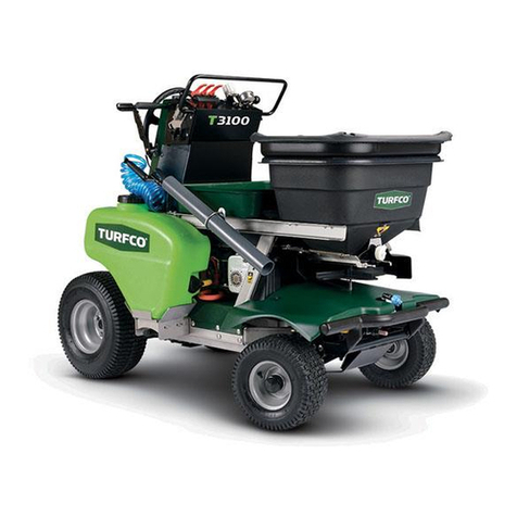
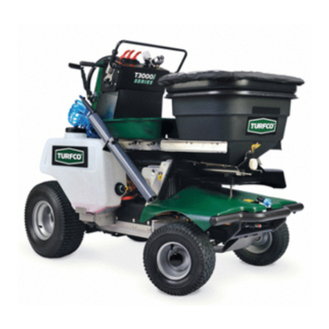
TURFCO T3000i Series User manual

®
OPERATOR’S MANUAL
MAINTENANCE MANUAL
PARTS LIST
TURFCO
®
T3000i™Series
Applicator
Spreader Sprayer
Product Number 85874
Starting Serial Number T00521
Product Number 85875
Starting Serial Number T00801
US Patent Number 8,056,828
Additional Patents Pending
Manual Number 668767 Rev C
DANGER - IF INCORRECTLY USED THIS MACHINE CAN CAUSE SEVERE
INJURY. THOSE WHO USE AND MAINTAIN THIS MACHINE SHOULD BE
TRAINED IN ITS PROPER USE, WARNED OF ITS DANGERS, AND SHOULD
READ THE ENTIRE MANUAL BEFORE ATTEMPTING TO SET-UP, OPERATE
OR SERVICE THE MACHINE.
TURFCO MFG. INC.
1655 101st Avenue NE • Minneapolis, Minnesota 55449-4420 USA
Phone (763) 785-1000 • FAX (763) 785-0556
2014 Turfco Mfg., Inc.
T3000iLOGO
T3000i Series
Applicator

285874 & 85875 Rev C
TURFCO T3000i SERIES APPLICATOR
All specications, information, illustrations or photos in this manual are
based on the latest information at the time of printing. The right is reserved to make changes without notice.
Table of Contents
Product Records........................................................................................................................................... 2
Specications ............................................................................................................................................... 3
Registered Trademarks and Patents............................................................................................................ 3
General Safety Practices.............................................................................................................................. 4
Recognizing Safety Warnings and Chemical Hazards ................................................................................. 6
Intended Use ................................................................................................................................................ 6
Description.................................................................................................................................................... 7
Operation -
Driving Operation -
Check List ....................................................................................................................................... 8
Operator Driving Controls ............................................................................................................... 8
Starting the Engine ......................................................................................................................... 9
Driving the Machine ...................................................................................................................... 10
Spreader -
Spreader Controls and Components ............................................................................................ 14
Operation for Trimming ................................................................................................................. 16
Spreading Operation on the Lawn ................................................................................................ 17
Sprayer -
Sprayer Controls and Components............................................................................................... 18
Spraying Operation....................................................................................................................... 20
Transporting the Machine to the Worksite.................................................................................................. 21
Troubleshooting Tables............................................................................................................................... 22
Calibration -
Spreader Calibration............................................................................................................................ 24
Sprayer Calibration.............................................................................................................................. 32
Service and Maintenance -
Inspection and Cleaning ...................................................................................................................... 36
Storage and Winter Storage Freeze Protection................................................................................... 37
Lubrication ........................................................................................................................................... 38
Recommended Service Schedule ....................................................................................................... 39
Location of Spray System Shutoff Valve and Strainer Screen ............................................................ 40
Adjusting Steering Cables ................................................................................................................... 40
V-Belt Identication.............................................................................................................................. 41
Electric Start Wiring Diagram .............................................................................................................. 41
Electrical Power Supply Connection........................................................................................................... 42
How To Obtain Parts and Service............................................................................................................... 42
Parts Lists................................................................................................................................................... 43
Decals ...................................................................................................................................................... 75
SS85874-01RevA
PRODUCT NUMBER
TURFCO MFG., INC.
1655 101st Avenue NE
Minneapolis, Minnesota
USA 55449-4420 www.turfco.com
(763) 785-1000 FAX (763) 785-0556
PRODUCT SERIAL
SERIAL NUMBER
Model Designation
T3000i Series Applicator Product Number
Date Purchased
Serial Number Engine Serial Number
Purchased From
IMPORTANT: Record the information from the serial number plate of your Turfco 3000i Series Applicator.
It will be necessary to furnish your Product Number and Serial Number when ordering parts.
Product Records
85874 - T3000i Series Applicator
85875 - T3000i Series Applicator
With Factory Installed
Electric Start Kit
TABLE OF CONTENTS

3
85874 & 85875 Rev C
TURFCO T3000i SERIES APPLICATOR SPECIFICATIONS
Registered Trade Mark and Patents
US Patent 8,056,828 - Additional Patent Pending
TURFCO® is a registered trademarks of Turfco Manufacturing, Inc.
T3000i™ and VARI-RATE™ are trademarks of Turfco Manufacturing, Inc.
SPYKER, ACCUWAY, and BORDER PATROL trademarks of Spyker Spreaders, Brinly-Hardy, Inc.
DELAVAN® is a trademark of Delavan Pumps Inc. - AQUATEC™ is a trademark of AquaTec International, Inc.
BRIGGS AND STRATTON® is a registered trademark of Briggs and Stratton Corporation. Inc.
THE ENGINE EXHAUST FROM THIS PRODUCT CONTAINS CHEMICALS KNOWN TO THE STATE OF
CALIFORNIA TO CAUSE CANCER, BIRTH DEFECTS OR OTHER REPRODUCTIVE HARM.
WARNING
Specications
Dimensions:
Width .......................................................... 35.5” Inches (0.90 Meter)
Height......................................................... 50” Inches (1.27 Meter)
Length ........................................................ 65” Inches (1.65 Meter)
Weight Empty................................................... 500 Pounds (227 Kg)
Weight Loaded
Spreader Full, Sprayer Tanks Empty.......... 675 Pounds (306 Kg) With Hopper Extension
Spreader Empty, Sprayer Tanks Full.......... 635 Pounds (288 Kg)
Spreader Full, Sprayer Tanks Full.............. 810 Pounds (367 Kg) With Hopper Extension
Operator Controls
Steering and Drive...........................Forward/Reverse Speed Control, Engine Throttle, Forward
Speed Control Pedal, Parking Brake and Freewheel Lever
Spreader..........................................Spreader Gate Open/Close, Vari-Rate Adjuster, Spinner
Speed Wide/Narrow, Trim Spread Border Control, Accuway
Spread Pattern Adjuster, and Gate Calibration Dial.
Sprayer............................................Full Width On/Off, Trim Width On/Off, Hand
Gun On/Off, and Spray Pressure Adjustment.
Production Rates
Spreading and/or Spraying..................4,000 Sq. Ft./Minute - 240,000 Sq. Ft./Hour
(371.6 Sq. Meters/Minute - 22,296 Sq. Meters/Hour)
Spreader Hopper Capacity ......................Approximately 2.9 Cubic Feet - 175 Pounds
(0.08 Cubic Meter - 79.4 Kg.) with Hopper Extension
Minimum/Maximum Spread Width
Full Spread..........................................18’ to 22’ Feet (5.49 to 6.7 Meter)
Trim Spread.........................................12’ to 14 Feet (3.66 to 4.27 Meter)
Sprayer Tank Capacity .............................16 US Gallons - 135 Pounds (8 gallons per tank)
(60.57 Liter - 61.3 Kg)
Minimum/Maximum Spray Width
Full Spray ............................................9’ to 11’ Feet (2.74 to 3.35 Meter) 9’ Effective
Trim Spray...........................................3’ to 4’ Feet (0.91 to 1.22 Meter)
Engine........................................................Briggs and Stratton INTEK 10.5 HP (7.8 kW), with 16 amp
Electric Voltage Regulator. Optional Electric Start Kit For
85874, Electric Start Standard For 85875.
Fuel Tank Capacity ................................... 2 Gallons (7.57 liters)
Transaxle................................................... Variable Speed with Brake and Freewheel Control
Tires ........................................................ Front - 13 x 6.50-6 Rear - 18 x 6.50-8
Maximum Transport or Operating Ground Speed.......... 5 MPH (8.04 Km/h)
Turning (Steering).............................................................. 9 Foot Circle (4.5 ft radius)
Maximum Slope Angle of Operation ............................... 15° Degrees
OPERATE ONLY IN AREAS WITH ADEQUATE VENTILATION. DO NOT OPERATE ENGINE IN ENCLOSED AREAS.

485874 & 85875 Rev C
TURFCO T3000i SERIES APPLICATOR
Safety on the job should always be a top priority.
Training and experience are important factors in the
safe operation of equipment. Please consider the
following information and realize that safe operation is
a matter of using common sense as it relates to the
machine, its maintenance, the operator, the training,
and the operating conditions. These are general
safety instructions that apply to most turf maintenance
equipment.
This list includes many, but not all, general
safety instructions as they relate to turf
equipment. Common sense must always be
used to determine the safest way to operate
a machine under specic conditions.
TRAINING:
● Always read the manual and view the
training video before operating a machine
for the rst time.
● Always read the warning decals before
operating a machine for the rst time.
● Always check the location and use of each
control before operating a machine for the rst time.
● Practice operating the machine in a safe area with no
obstructions until becoming familiar with the controls.
If you have questions, ask your supervisor or call the
factory.
CLOTHING:
● Clothes should be snug t. Loose tting clothing
is hazardous because it may get caught in the
mechanism during service or operation.
● Remove jewelry before operation. Again, jewelry may
get caught in the mechanism.
● Wear shoes that will protect your feet. Steel toed safety
shoes should be considered for many situations.
● Hard Hat: The use of a hard hat should be considered
when using equipment on a golf course. The danger
of being hit by a golf ball should be a major concern
as well as protection while operating under trees .
● Respirators: When
operating in dusty,
windy conditions,
wear a respirator. This
is also an important
consideration if
operating equipment
while spreading or
spraying chemicals and fertilizers.
● Eye Protection: Safety glasses and/or face shields
should be considered when operating, as well as
working in close proximity to high speed rotary
equipment. Watch for rotary mowers, edgers, brush
and string trimmers. Rotary mowers can throw debris
at speed up to 200 MPH.
● Hearing: If the noise level of the equipment is too
loud, consider the use of ear protection. Do not use
stereo headsets during operation. This is a distraction
that may lead to an accident. Headsets also make
it difcult to hear other people and equipment while
operating in the work area.
● Gloves: Use gloves when handling sharp or hazardous
objects, chemicals and fertilizers.
THE OPERATOR:
● The operator should never use a machine while under
the inuence of alcohol or drugs. The operator should
be aware of the hazards of working in the sun and
should take proper precautions to avoid heat stress
and dehydration. Use sun screen products when
necessary.
● The operator should never attempt to ride a machine
that is not designed for that propose. Do not allow
others to ride a machine that is not designed for
passengers.
● Care should always be taken when mounting and
dismounting a riding machine. Prevent injuries and
falls by making sure the operator does not slip. Unless
it is an emergency, do not jump off a machine. Injury
may result when an operator’s foot slips trying to jump
from a machine.
● Keep hands and feet away
from the spinner wheel,
hopper mixing devices and
drive components. Shut
off the engine and remove
ignition wire when servicing
the spinner wheel, hopper
mixing devices and drive components.
● Do not operate any equipment at unsafe speeds.
Speeds should be reduced when turning or operating
on slopes. The operator must use common sense to
determine a safe speed based on the equipment, the
load, the slope, the surface, and other conditions that
may affect safe operation.
● The operator must be aware of the conditions around
the area. Be careful to observe other people and
machines.
General Safety Practices
safe85870-3
safe85870-1
WEAR APPROPRIATE
PROTECTIVE EQUIPMENT (PPE)
safe85872-4
SAFETY

5
85874 & 85875 Rev C
TURFCO T3000i SERIES APPLICATOR
● Beware of slippery conditions. Wet turf can be
encountered on slopes, when turning or stopping, or
at higher speeds.
● If required to lift, an operator should ask for help if the
object is too heavy. The operator should lift with his or
her legs instead of the back. Care should be taken to
avoid twisting the back while lifting a heavy load.
● Never allow children to operate the machine.
THE MACHINE:
● Do not modify the machine in any manner. Always
check the machine to make sure it is in good working
order.
● Do not place hands or feet near
moving or rotating parts. Inspect to
insure that all guards are in place.
Do not operate a machine without
all guards in place. Be aware of
thrown objects from the spinner
wheel.
● Check to assure that all controls are in good operating
condition. Make sure the brakes are operating
properly.
● Do not overload machinery. The components
are designed for certain weights and capacities.
Overloading machine will cause unsafe conditions.
● Shut off the engine before servicing the machine.
Check machines on a level area. Machines on a slope
may roll when the engine is off.
● Refer unfamiliar repairs and adjustments to mechanics
that have been trained to do them properly.
● Replace decals that have become damaged or
illegible.
ENGINES:
● Prevent accidental starting by removing the spark plug
wire when servicing the engine or the equipment.
● Do not strike the ywheel with a hammer or any
hard object. This may cause the ywheel to shatter
in operation. Use the correct tools to service the
machine.
● Pull the starter cord slowly until resistance is felt. Then
pull the cord rapidly to avoid kickback and to prevent
hand or arm injury.
● Do not run the engine in an enclosed area. The
exhaust gases contain carbon monoxide, an odorless
and deadly poison.
Engine Exhaust Contains Chemicals Known to
the State of California to Cause Cancer, Birth
Defects or Other Reproductive Harm.
● Do not store, spill, or use gasoline near an open ame,
nor near an appliance like a stove, furnace, or water
heater that uses a pilot light or can create a spark.
● Do not refuel indoors or in an unventilated area. Check
the fuel level. Do not over ll. Do not add fuel while the
machine is hot because spilled fuel may cause a re.
Use fresh gasoline. Stale fuel can gum the carburetor
and can cause leakage. Check the fuel lines and
ttings frequently for cracks and leaks. Replace if
necessary.
● Do not remove the fuel tank cap or ll fuel tank while
the engine is hot or running. Allow the engine to cool
before refueling.
● Do not operate the engine if gasoline is spilled or when
the smell of gasoline is present or other explosive
conditions exist. Move the equipment away from
the spill and avoid any ignition until the gasoline has
evaporated.
● Do not transport the engine with fuel in the tank.
● Do not start the engine with the air cleaner and/or the
air cleaner cover removed.
● Do not choke the carburetor to stop the engine.
Whenever possible, gradually reduce the engine
speed before stopping.
● Do not tamper with the governor springs, links or other
parts to increase the engine speed. Run the engine at
the speed set by the equipment manufacture.
● Do not check for a spark with the spark plug removed.
Use an approved tester. Do not crank the engine with
the spark plug removed. If the engine is ooded, place
the throttle in fast and crank until the engine starts.
● Keep the cylinder ns and the governor parts free of
dirt, grass, and other debris which can affect engine
speed.
● Do not operate the machine without a
mufer. Inspect the mufer periodically
and replace it if it is leaking or worn. If
necessary, replace it with correct mufer.
Do not touch a hot mufer, cylinder, or n.
It may cause burns.
● Do not operate the engine with an accumulation of
grass, leaves, or other combustible material in the
mufer area.
● Do not use the engine on any forest covered, brush
covered, or grass covered unimproved land unless
a spark arrester is installed in the mufer. The spark
arrester must be maintained in working order by
the operator. In the State of California, the above is
required by law (Section 4442 of the California Public
Resources Code). Other state may have similar laws.
Federal laws apply on federal lands.
safe85870-2
safe85870-5
SAFETY
WARNING

685874 & 85875 Rev C
TURFCO T3000i SERIES APPLICATOR
Recognizing Safety Warnings Used In Manual
LOOK FOR THE SAFETY HAZARD WARNING SYMBOLS
The symbol is used to alert the operator of safety hazards.
It is used in conjunction with the words DANGER, WARNING, and CAUTION.
“DANGER” identifies immediate hazards which will result in serious injury or death.
“WARNING” identifies potential hazards which could result in serious injury or death.
“CAUTION” identifies hazardous situations which may result in minor injury and/or could result in
damage or destruction of equipment.
WARNING CAUTION
DANGER
safe-04
Safety
READ ALL CHEMICAL WARNING LABELS.
PROTECT YOURSELF FROM CONTACT
OR INHALATION OF CHEMICALS.
safe-77
WEAR APPROPRIATE
PROTECTIVE EQUIPMENT (PPE)
BE AWARE OF THE HAZARDS OF THE CHEMICALS THAT ARE BEING USED AND APPLIED.
ALWAYS WEAR PERSONAL SAFETY EQUIPMENT TO PROTECT FROM ALL HAZARDS.
REFER TO THE CHEMICAL MANUFACTURES SAFETY WARNINGS FOR THE PRODUCT BEING
APPLIED, MIXED, TRANSPORTED, OR STORED.
CHEMICALS CAN BE POISONOUS, CAUSE BURNS, CAUSE SERIOUS ILLNESS OR DEATH.
PROTECT YOURSELF FROM CONTACT, INHALATION, EXPOSURE AND/OR OVEREXPOSURE
READ THE LABELS FROM THE PRODUCT.
THE TURFCO T3000i DOES NOT PROTECT THE OPERATOR OR BYSTANDERS FROM
THE HAZARDS OF EXPOSURE OR OVEREXPOSURE TO CHEMICALS.
THE TURFCO T3000i DOES NOT PROTECT THE OPERATOR OR BYSTANDERS FROM
THE HAZARDS OF CHEMICALS BEING USED DURING APPLICATION OR AFTER
APPLICATION.
THE TURFCO T3000i DOES NOT PROTECT THE OPERATOR OR BYSTANDERS FROM
THE HAZARDS OF CHEMICALS DURING MIXING, DURING STORAGE, OPERATION, OR
DURING TRANSPORTATION OF THE MACHINE.
DANGER
DANGER
SAFETY
PROTECT YOURSELF!
Read, Understand and Follow the Chemical
Manufacturers Warning Labels and
Instructions.
Read and Follow the Material Safety Data
Sheet (MSDS) For All Chemicals Being Used.
Wear the Appropriate Personal Protective
Equipment (PPE) To Protect Yourself In
Accordance With the MSDS Sheet and the
Chemical Manufacturers Labels, Handling
Instructions and Application Instructions.

7
85874 & 85875 Rev C
TURFCO T3000i SERIES APPLICATOR
Description
The Turfco T3000i Applicator is an easy to operate,
comfortable, high production lawn applicator for dry
and spray products. The lawn applicator is capable
of spreading fertilizer or spraying at the rate of 4000
square feet per minute (371 square meters per
minute). The T3000i Applicator is a 4 wheel machine
using standard automotive style steering for directional
control and operator comfort. The front wheels are
the steering wheels and the rear wheels are the drive
wheels.
DS85874-01RevA
SPREADER
HOPPER
SPRAY
NOZZLES
OPERATOR
CONTROLS
OPERATOR
POSITION AND
PLATFORM FIGURE 1
Welcome
Welcome to the Turfco T3000i Series Applicator. This manual will describe the machine, give correct
operating procedures, and help you learn and understand correct operation. Operation of this
machine without training can result in injury to the operator or damage to the machine.
The operators position is standing on a vibration
isolated platform on the rear of the machine. The
forward and reverse speeds are controlled by using a
simple directional hand control allowing the operator
total control of the speeds from 0 to 5 MPH (0 to 8.04
Km/h). Braking is provided by a dynamic braking
system within the hydrostatic transmission and a hand
operated parking brake. Releasing the speed control
(and the foot operated forward speed control pedal)
will stop the machine. The machine is designed so
that it will stop movement if the operator dismounts
and releases the speed control.
DESCRIPTION
The Turfco T3000i™ Applicator is a self-powered ride-on spreader/sprayer. The T3000i is intended
to be used for the application of properly prepared turf care liquid spray products and turf care granular
products. The T3000i is NOT intended to be used for any purpose other than the application of properly
prepared turf care products to the turf. Operation is intended to be at properly prepared worksites only.
Intended Use
Product Number 85874 - T3000i Series Applicator
Product Number 85875 - T3000i Series Applicator with Factory Installed Electric Start Kit

885874 & 85875 Rev C
TURFCO T3000i SERIES APPLICATOR
Turfco T3000i Applicator Operator Driving Controls (See Figure 2)
Before driving the applicator become familiar with the operator controls.
A. PARKING BRAKE LEVER
B. FREEWHEEL LEVER
C. ENGINE THROTTLE CONTROL
D. FORWARD/REVERSE SPEED CONTROL
E. FORWARD SPEED CONTROL PEDAL
F. STEERING WHEEL
G. OPTIONAL ELECTRIC START
Take time to become
familiar with all the
controls before you
attempt to drive this
machine.
Become comfortable with
the reach and movement
of the Speed controls, the
Steering Wheel and the
locations of the Engine
Throttle, Freewheel Lever,
and Parking Brake.
FREEWHEEL
LEVER
PARKING
BRAKE
LEVER
ENGINE
THROTTLE
CONTROL
STEERING
WHEEL
FORWARD
SPEED
CONTROL
PEDAL
FORWARD/REVERSE
SPEED CONTROL
OP85872-02
FIGURE 2
OPTIONAL
ELECTRIC
START
OPERATION
Before Operating the T3000i Series Applicator and Before Starting the Engine,
1. Read the Operators Manual and Watch the Operation CD.
2. Check the oil in the engine.
3. Check air pressure in the front and rear tires. Inate to PSI shown on tire.
3. Fill the machine with fresh approved gasoline.
4. Inspect the machine for any loose nuts, bolts or hardware or anything that does not look normal.
5. Check all guards and covers to make sure they are secure.
6. Become familiar with the controls. Stand on the operators platform and test operate all the driving
controls.
7. Do not start the engine - you are not ready yet.
safe-06
WARNING
Warning: Driving the T3000i
Applicator without training and
practice can cause damage to the
machine and injure the operator.
OPERATION
It may take several hours
of practice before one has
the skill level required to
properly applicate a lawn.
Operation of the T3000i
Applicator before one has
developed the proper skill
level can cause damage
to the machine, operator
or the lawn.

9
85874 & 85875 Rev C
TURFCO T3000i SERIES APPLICATOR
DRIVING CONTROLS
1 . Locate the Parking Brake. Test the movement of the lever to the ON and OFF positions. The brake
should always be set in the ON position when the operator is not present on the machine.
2 . Locate the Freewheel Lever. This lever puts the transaxle in a “neutral” state allowing the machine
to be pushed by hand when the engine is not running. The lever must be in normal position (to the
left) during operation.
3 . Locate the Engine Throttle Control. Test the movement of the lever. Note the range of movement
- from Stop, Slow, Fast and Choke. The throttle should be set at “Fast” during operation to maintain
a constant and even ground speed.
4 . Locate and test the movement of the Forward/Reverse Speed Control. Make sure your hands can
reach as needed for full movement of the control (either right or left hand control). The control operates
by Slowly squeezing the control forward for forward movement, pull back for reverse movement, or
releasing to stop movement.
5 . Locate and test the Forward Speed Control Pedal. This is the pedal by your right foot. By Slowly
pressing the pedal with your foot, you can move the Forward/Reverse Speed Control handle forward
without using your hands. As long as you have the pedal depressed with your foot the speed lever
control will remain in a forward position. Remove your foot from the Forward Speed Control Pedal
and the speed control will return to the neutral position. Operation is for forward movement only, the
pedal is not used for reverse movement.
6. Test the full movement of the Steering Wheel. The steering uses standard automotive style of steering the front
wheels.
After you are totally comfortable with the location and movement of the operator controls,
you are now ready to start the engine.
STARTING THE ENGINE
Before starting the engine, check that the fuel tank shut-off valve (located on fuel line before lter) is open.
1. Set the parking brake before starting the engine. Check the Freewheel lever.
2. Make sure Forward/Reverse Speed Controls are in the neutral (not engaged) position. Make sure
Forward Speed Control Pedal is not depressed.
3. Move the throttle control lever upward to the choke (start) position.
4. Operator must be off the machine before starting.
5. Start the engine by pulling on the Starting rope on the right side of the console. NOTE: If equipped
with the optional electric start, use key (ignition switch) to start engine. If the electric start battery is
dead, the engine can still be started with the rope (key must be in the ON position).
6. Allow engine to run on choke for a very short time and then move the throttle lever to slow run
position. Allow to machine to run a few minutes to warm up.
FREEWHEEL
ON
OFF
PARKING
BRAKE FORWARD
SPEED
CONTROL
ON
CHOKE
STOP STOP
SLOW
FAST
FORWARD
REVERSE
FREEWHEEL
ON
OFF
PARKING
BRAKE
FORWARD
SPEED
CONTROL
ON
CHOKE
STOP STOP
SLOW
FAST FORWARD
REVERSE
FREEWHEEL
ON
OFF
PARKING
BRAKE FORWARD
SPEED
CONTROL
ON
CHOKE
STOP STOP
SLOW
FAST FORWARD
REVERSE
FREEWHEEL
ON
OFF
PARKING
BRAKE
FORWARD
SPEED
CONTROL
ON
CHOKE
STOP STOP
SLOW
FAST FORWARD
REVERSE
FREEWHEEL
ON
OFF
PARKING
BRAKE FORWARD
SPEED
CONTROL
ON
CHOKE
STOP STOP
SLOW
FAST
FORWARD
REVERSE
FREEWHEEL
ON
OFF
PARKING
BRAKE FORWARD
SPEED
CONTROL
ON
CHOKE
STOP STOP
SLOW
FAST
FORWARD
REVERSE
OPERATION
Take Care Of Your Pump.
The pump will start operating as soon as the engine is started. When not spraying, the tanks should be at least 50%
full of water to keep the pump running cool. While the pump is designed to be able to withstand being operated dry,
running the pump for extended periods with tanks empty could cause damage to the pump or lead to early failure.
IGNITION
ON
OFF
START

10 85874 & 85875 Rev C
TURFCO T3000i SERIES APPLICATOR
DRIVING THE MACHINE
(See Figures 3, 4 and 5)
To begin your driving lesson you will
need a large smooth paved level area
like a parking lot.
Forward and Reverse Operation
(See Figure 3)
1. Stand on the operators platform
before touching anything. Do Not
stand on the yellow pedal.
2. Place one hand on the support bar
and grip the steering wheel with the
other hand.
3. Release the Parking Brake.
4. Using the hand on the support
bar, move the speed control lever
slowly towards the support bar.
The machine should move ahead
slowly. Slowly moving the speed
control bar closer to the support bar
will increase the forward speed.
5. The machine has a braking system in
the transmission that automatically
stops the machine when the speed
control is released. Let go of the speed control and it will
go to neutral applying the brake. The machine will quickly
come to a full stop in just a few feet of travel. Try this
many times to get used to the braking action.
● Go ahead slowly and release the speed control lever.
The control will return to the neutral position and the
machine will stop. The machine will stop quickly.
● You may speed up a little as you become more
accustomed to the start and stop characteristics of the
machine. Continue this for several minutes gradually
getting more speed and becoming used to the stopping
motion.
● Also try the same movement using the reverse lever on
the left side.
6. The reverse speed control is under the left side support
bar. Move the reverse speed control upward toward
the support bar slowly. The machine will slowly start
moving in reverse. Try this a few times to get used to the
movement and control.
Using Forward Speed Control Pedal (See Figure 4)
The T3000i Applicator has a “Forward Speed Control Pedal”.
This pedal can be used to control forward speed, the same as
the forward speed control handles. This allows the operator
to use his hand to operate the other spreader and sprayer
controls on the machine.
FORWARD/REVERSE
SPEED CONTROLS
FORWARD
REVERSE
REVERSE
OP85872-09
SUPPORT BAR
FIGURE 3
PARKING
BRAKE
ON
OFF
YELLOW
FORWARD
SPEED
CONTROL
PEDAL
FORWARD/REVERSE
SPEED CONTROLS
FIGURE 4
OP85872-07
FORWARD
SPEED
CONTROL
ON
FORWARD
REVERSE
OPERATION

11
85874 & 85875 Rev C
TURFCO T3000i SERIES APPLICATOR
Steering the Machine
Now you are ready to try the steering and driving the machine on the parking lot. Like your car, the Turfco T3000i
Applicator steers uses a steering wheel. A full spin to the right will give you a full right turn and a full spin to the left
give you a full left turn.. The steering wheel is equipped with a wheel spinner knob to make this easier.
Drive the machine in all modes; fast, slow, turns, gure 8’s and reverse backing. One thing you must get accustomed
to is steering and stopping of the machine. Do this for at least 10 minutes
before we move on to the other controls.
● Drive the T3000i Applicator ahead slowly 10 feet and make a 180º degree
turn using the steering wheel. Continue doing this several times gradually
increasing the speed. Do not try to make a full 180º degree turn at full speed
until you are well accustomed to the machine.
● Continue with other driving maneuvers such as gure “8’s”, circles, 90º
degree turns and many 180º degree turns. The machine is designed to do a
full 180º degree turn in 9 feet, to match the effective operation width of the
spread and spray. Therefore the operator must practice this turn until they
have it mastered.
To operate the Forward Speed Control Pedal, step on the
yellow colored pedal (located on the operators platform)
and slowly press down. Notice that as you press the pedal
the forward speed control handles are moving forward. The
further you press the pedal, the further the speed control
handles move. As long as pressure is applied on the pedal,
the speed control will remain in forward position.
● Try this operation a number of times so you become
very familiar with the operation of the Forward Speed
Control Pedal. You will need to know this for later
operation of the machine.
Note: The pedal is for forward movement only, the pedal
is not for reverse.
Using 3-1/2 MPH Speed Lever (See Figure 5)
The T3000i Applicator has a 3-1/2 mph speed lever
mounted on the right hand forward/reverse speed control
handle to provide a slower ground speed. The lever limits
the amount of forward movement of the speed control
handle. Ground speed will be approximately 3-1/2 mph
(5.6 Km/h). THE 3-1/2 MPH SPEED LEVER IS FOR
SPREADING ONLY - DO NOT USE WHEN SPRAYING.
● To operate the 3-1/2 MPH speed lever, simply move the
lever in a forward position and set. When the forward
speed control handle is moved forward, the lever will
touch the support bar and stop any further speed
increase. You will be going at a slower 3-1/2 mph
speed. Refer to the 3-1/2 mph spreader calibration.
● To return to full speed operation, return the lever in the
off position and set.
The 3-1/2 mph speed lever can be used with or without the
speed control pedal.
9 FOOT
TURNING
CIRCLE
OP85874-06
OPERATION
FIGURE 5
3-1/2 MPH
SPEED
CONTROL
LEVER
OP85872-14RevC
SPEED
LEVER
ON
SPEED
LEVER
OFF
RIGHT HAND
SPEED
CONTROL
HANDLE
SPREADING ONLY!
DO NOT USE WHEN
SPRAYING.

12 85874 & 85875 Rev C
TURFCO T3000i SERIES APPLICATOR
Climbing Curbs
(See Figure 6)
Now that you are familiar with driving the T3000i Applicator, you are ready to try all the same turns and
maneuvers you learned in the parking lot on the lawn. Now you are ready to move up into the lawn and
practice turns, trimming, getting close around trees and obstacles.
You should always use curb cuts or driveways when ever possible. But, in the case they are not
available you should know how to climb a curb with the machine. You should always dismount when
climbing curbs or other obstacles with the machine. Hold the steering wheel rmly and advance the
machine slowly until the entire machine is on the lawn. Stop and remount the machine.
1. Approach the curb at a 45º degree angle. Stop the machine a few inches from the curb.
2. Dismount the machine keeping your hands on the support bar and steering wheel
3. Hold the steering wheel rmly and slowly advance the speed of the machine.
4. The machine should slowly climb over the curb. The operator may remount as soon as the machine
is on top of the curb.
5. The same technique is used for going down over a curb.
The Turfco T3000i Applicator is not designed to be operated on any incline
or slope exceeding 15º Degrees. Operation on inclines of more than 15º
degrees can result in injury and/or damage to the machine.
Operation on inclines exceeding the 15º degree limit can cause spillage of
materials
CURB
APPROACH
CURBS AT
45° DEGREES
OP85872-04
FIGURE 6
WARNING
OPERATION

13
85874 & 85875 Rev C
TURFCO T3000i SERIES APPLICATOR
15° MAXIMUM 15° MAXIMUM
OP85872-05
FIGURE 7
15° MAXIMUM 15° MAXIMUM
Operation on Slopes, Inclines or Hills
(See Figure 7)
For safety reasons, the best way to drive up or down a slope is at a 45º degree angle to the slope. This will
keep you from being directly above or under the mass of the machine. This machine is only rated to go on
slopes of 15º degrees or less. Slopes of more than 15º degrees could cause injury to the operator or damage
to the machine. Roll overs can occur, using the machine to traverse along a slope of more than 15º degrees
is not recommended. You should always use walking applicators on slopes more than 15º degrees.
● Do not turn the machine while on a slope or incline.
● If one must operate across a slope, angle the machine 45º degrees to the direction of the incline no
matter if you are going up or down the slope.
● Do not operate the machine across the face of a slope or at 90º degree angles to the slope.
The Turfco T3000i Applicator is not designed to be operated
on any incline or slope exceeding 15º Degrees.
Operation on inclines of more than 15º degrees can result in
injury and/or damage to the machine.
Operation on inclines exceeding the 15º degree limit can cause spillage of materials
WARNING
OPERATION

14 85874 & 85875 Rev C
TURFCO T3000i SERIES APPLICATOR
THE SPREADER
The spreader has several components and controls you should be familiar with before operating the machine.
1. HOPPER (See Figure 8) - The spreader hopper size is 2.9 cubic feet and holds 175 pounds (0.08 Cubic Meter/
79.4 Kg.) of material.
2. SPREADER GATE (See
Figure 8) - The Spreader
Gate opens allowing the
material from the hopper
to fall onto the spinner
wheel for spreading. The
gate is operated from
Spreader Gate Open/
Close Control lever on
the right side of the
operators control.
3. SPREADER GATE RATE
ADJUSTER DIAL (See
Figure 9) - The Spreader
Gate Rate Adjuster Dial,
is a round white plastic
cam on the front of the
spreader hopper. This
cam sets the exact
opening of the spreader
gate. The exact setting
for the gate dial should
only be set by licensed
persons.
4. “ACCUWAY” SPREAD
PATTERN ADJUSTER
(See Figure 9) - The Spread Pattern Adjuster moves the position of a black plastic wedge that is under the
hopper gate opening. When the gate is opened, the wedge controls where the material lands on the spinner
wheel. This affects how fast the material exits the spinner wheel and changes the throw of the material. The
wedge can be adjusted to throw more material to the right, more to the left, or an equal right to left pattern.
More detailed information about
the adjuster can be found in the
spreader calibration section of
this manual
The Accuway Spread Pattern
Adjuster must be readjusted if
the Spreader Gate Rate Adjuster
Dial has been changed or when
a different product is being used.
Consult the calibration section
in this manual for proper
adjustment.
“ACCUWAY”
SPREAD PATTERN
ADJUSTER
SPREADER
GATE RATE
ADJUSTER
DIAL
TRIM SPREAD
BOARDER
PATROL
DEFLECTOR
OP85872-21
SPREADER
SPINNER
WHEEL
FIGURE 9
SPREADER SPINNER
WHEEL AND SHAFT
PULL PINS
OPERATION
TRIM
SPREAD
BOARDER
PATROL
CONTROL
TRIM
SPREAD
BOARDER
PATROL
DEFLECTOR
SPREADER
HOPPER
SPREADER GATE
OPEN/CLOSE CONTROL
OP85872-13
SPINNER SPEED
CONTROL
SPREADER
SPINNER
WHEEL
FIGURE 8
SPREADER
GATE

15
85874 & 85875 Rev C
TURFCO T3000i SERIES APPLICATOR
LOCKING KNOB
SPREADER GATE
OPEN/CLOSE CONTROL HANDLE
VARI-RATE
ADJUSTABLE
GATE STOP
FIGURE 10
SPREAD TRIM BORDER PATROL
ON
SPREADER SPINNER
WHEEL SPEED
CONTROL
OP85872-14
OFF
NARROW
WIDE
OPEN
CLOSE
60%
FULL
4
3
OPERATION
5. SPINNER WHEEL (See Figure 8 and 9) - The
Spinner Wheel broadcasts the material from
the hopper. The speed of the spinner wheel is
controlled by the Spinner Speed Control.
6. SPINNER SPEED CONTROL (See Figure 8 and
10) - The Spinner Speed Control lever allows the
operator to speed up or slow down the spinner
wheel to vary the spread pattern width. Push the
Spinner Speed Control lever full ahead for full
application width and pull back for the narrow or
trim width. A slower spinner wheel speed results
in a narrower spread width (about 7 foot wide)
for use in narrow spots, trimming, and to avoid
putting product where it is not wanted.
Note: The Spinner Speed Control lever should
only be moved when the engine is running. No
damage will occur if the lever is moved while the
engine is not running, it is just better for the belts
and pulley to be moving when activated.
7. SPREADER GATE OPEN/CLOSE CONTROL
(See Figure 10) - The Spreader Gate Open/
Close Control handle controls the opening of
the spreader gate. Push forward to the open the
gate or pull back to close.
8. VARI-RATE ADJUSTABLE GATE STOP (See
Figure 10) - Vari-Rate Adjustable Gate Stop is
located next to the spreader gate handle. The
stop will limit the movement of the spreader
gate control handle. This causes the spreader
gate to stop at a preset opening size that is less
than 100% open (opening must be preset during
calibration). To use the Vari-Rate stop, simply
push the lever in as you open the gate. The lever
will snap in to a more vertical position and stop at
the gate stop. To bypass the stop, tip the control
out as you move it forward to open the gate and
the handle will miss the stop allowing the gate to
fully open.
The Vari-Rate Adjustment Gate Stop should only
be set by the person calibrating the spreader.
This should never be done in the eld and
should be changed whenever the calibrated
rate is changed. The exact setting for the Vari-
Rate should only be set by licensed persons.
Refer to the spreader calibration section in this
manual.
9. SPREAD TRIM BORDER PATROL (See Figure
8 and 10) - The Spread Trim Border Patrol
deector is on the left side of the hopper and
is operated by a lever on the left side of the
operators panel. The Border Patrol deector is
operated by pushing the lever down for trim and
up for full width application.

16 85874 & 85875 Rev C
TURFCO T3000i SERIES APPLICATOR
OPERATION
OPERATION FOR TRIMMING
To get clean trimming with little off target fertilizer on
sidewalks and curbs use these tips.
● Place the Trim Guard Handle in the down
position.
● Move the Spread Width to the Narrow position.
● Open the Gate Opening Handle to the left and
forward against the Vari-Rate Stop.
Note: When trimming drive the unit with the left front
tire approximately 6 inches away from the area
you are trimming i.e. sidewalks, curbs, ower beds
and etc. Prills coming off the front cover and left
front tire will cover this area.
Also when you make your rst full spread pass,
make sure you are throwing fertilizer to the center
of your trim tire tracks so you get 100% coverage.
Trimming to Right with Full Width Spread
When trimming to the right, you only need 60% of
the full gate opening. Use all the Spreader controls
together for a very accurate trim along a side walk
and curb area.
1. Adjust the Vari-Rate Adjustable Gate Stop so it is
at 60% of full open setting for your product (Licensed
Operator Adjustment Only).
2. Place the Trim Spread
Border Patrol handle down
in the trim position.
3. Open the Spreader
Gate Open/Close Control
handle. Handle should be
positioned to stop at Vari-
Rate stop - See Position
“B” in Figure 11. This way
you will be spreading only
to the right and the rate will
be at 60% of the full rate.
The spread pattern will
start approximately 2” to
3” inches to the left of the
front tire and spread out to
the far right.
Trimming to Right with
Narrow Width Spread
This is used for the narrow
strip between sidewalks
and the street.
1. Adjust the Vari-Rate
Adjustable Gate Stop so
it is at 60% of full open
setting for your product (Licensed Operator Adjustment
Only).
2. Move the Spinner Speed Control handle to the narrow
position. This will reduce the spinner speed and narrow
spread width.
3. Place the Trim Spread Border Patrol handle down in
the trim position.
4. Open the Spreader Gate Open/Close Control handle.
Handle should be positioned to stop at Vari-Rate stop
- See Position “B” in Figure 11. This way you will be
spreading a narrow pattern (approximate 5 to 6 foot) at
60% of the full rate and it will only be going to the right
(See Figure 12).
Reducing Spread Pattern 60% To Go Thru a Narrow
Area.
1. Adjust the Vari-Rate Adjustable Gate Stop so it is
at 60% of full open setting for your product (Licensed
Operator Adjustment Only).
2. Move the Spinner Speed Control handle to the narrow
position. This will reduce the spinner speed and narrow
spread width.
4. Open the Spreader Gate Open/Close Control handle.
Handle should be positioned to stop at Vari-Rate stop
- See Position “B” in Figure 11. This way you will be
spreading a narrow pattern (approximate 9 foot or less)
at 60% of the full rate.
SPINNER
SPEED
WIDE
NARROW
VARI-RATE
ADJUSTABLE
GATE STOP
HANDLE TIPPED
OUT TO BYPASS
VARI-RATE STOP
HANDLE PUSHED
FULLY FORWARD
FOR 100%
GATE OPENING
HANDLE PUSHED
FORWARD TO
VARI-RATE 60%
STOP SETTING
HANDLE PULLED
FULLY BACK
TO CLOSE
GATE
OP85874-30RevC
FIGURE 11
SPREADER GATE
OPEN/CLOSE
CONTROL
HANDLE
SPREADER
SPEED
CONTROL HANDLE
TRIM SPREAD
BORDER PATROL
CONTROL
HANDLE
A B C D
3-1/2 MPH
SPEED LEVER
SPREADER GATE
OPEN
CLOSE
ON
OFF
TRIM
SPREAD

17
85874 & 85875 Rev C
TURFCO T3000i SERIES APPLICATOR OPERATION
Trimming to Right Using the 3-1/2 MPH Speed Lever
1. Set the 3-1/2 mph Speed Lever (on the right speed control handle) in the forward
position. This will maintain your forward speed at 3-1/2 mph.
2. Place the Trim Spread Border Patrol handle down in the trim position.
3. Set the white cam dial on the front of the hopper so it lines up with the setting
determined by your calibration at 3-1/2 mph.
4. Open the Spreader Gate Open/Close Control handle. Put the handle in the far
right forward position or away from the machine - See Position “D” in Figure 11.
This is the position normally used for spreading an 18 foot swath.
5. Put the Spreader Speed Control Handle in the Narrow Position. This is the
position normally used for spreading an 12/6 foot spread swath.
SPREADING OPERATION ON THE LAWN
All lawns are different. Most accidents happen when operators are not familiar with
either the machine or the terrain on which they will be using the machine.
1. Practice with the T3000i before you try to operate it on a lawn. Practice in all
kinds of conditions for at least 30 minutes. Simulate close quarter operation (i.e.
between a fence and AC unit) before you actually try it. Climb curbs, get used to
operation on mild slopes and making turns. Be totally familiar with your machine
before you every try to apply products to a lawn. You will need practice before you
become good at the controls and driving at the same time.
2. BEFORE YOU GO ON THE LAWN, Place the screen in the hopper, ll the hopper
with the material you are going to spread.
3. BEFORE YOU APPLICATE ANYTHING, go on the property to be treated and
drive slowly around the entire perimeter. Note or mark all obstacles, holes, rocks
or anything that can be a hazard, harmed by the machine or cause damage to the
machine.
4. Trim out the property to be treated. Set the Border Patrol Deector in the down or Trim position. You will be going
around the property clockwise doing a trim strip around the outer edge of the property. Keep your left side wheels
about 6 inches inside any walks or drives you do not want product on. As you start ahead open the spreader gate
to the 60% setting as you are only spreading to the right. The Border Patrol Deector will keep the fertilizer from
going “off target” to the left.
5. Stop after going around the entire edge of the property. With the settings in the same trim positions, you will want
to make a counterclockwise pass around all objects on the property.
6. Stop. Put the Border Patrol up. You will now make
another pass around the property exactly 6 feet out
from the last pass tire track. The Spreader gate will be
in the full open position. When you have nished this
pass you will have a 13 foot band around the entire
property to be used for turning. You are now ready to
applicate the lawn.
7. To applicate go straight across the lawn, with the
spreader gate in the full open position. As your spread
hits the 13 foot turning band on the side of the lawn,
turn off the spread and make a 180º degree turn. The
machine will come straight at 6 foot from your last tire
track. Turn on the spread, keeping the T3000i 6 foot
from your last tire track all the way across the lawn.
Continue this procedure until you are done with the
lawn.
OP85872-17
TRIM
SPREAD
FIGURE 12
FULL
SPREAD
SPINNER
SPEED
WIDE
SPINNER
SPEED
NARROW
18 TO 19 FEET
SPINNER
SPEED
WIDE
SPINNER
SPEED
NARROW
9 FOOT
OP85872-31
TRIM
SPREAD
9 FEET
9 FEET
6 FEET
FULL
SPREAD

18 85874 & 85875 Rev C
TURFCO T3000i SERIES APPLICATOR
The Sprayer
The sprayer has several components and controls you should be familiar with before operating the machine.
1. PUMP (See Figure 15) - The pump is located under the machine. The pump will start operating as soon as the
engine is started. The only control for the pump is the pump pressure control.
Take Care Of Your Pump.
When not spraying, the tanks should be at least 50% full of water to keep the pump running cool.
While the pump is designed to be able to withstand being operated dry, running the pump for extended
periods with tanks empty could cause damage to the pump or lead to early failure.
2. PUMP PRESSURE CONTROL AND GAUGE (See Figure 14) - The Turfco T3000i Applicator has an adjustable
pressure spray system. The gray knob adjusts the pressure and the pressure is indicated on the gauge. The amount
of pressure in the system controls the amount of product being sprayed. Calibration, set-up and adjustment of
this control can only be done by licensed personnel. The pump pressure should never be adjusted by the
operator in the eld. Consult the sprayer calibration adjustments in this manual. Watch the pressure gauge during
operation. The gauge should read 40 PSI when spraying. Note: If the tanks are empty, the gauge will read zero.
3. TANKS (See Figure 14) - The Turfco T3000i Applicator has two liquid tanks. Each Tank has a capacity of 8
gallons for a total of 16 gallons (60.56 liters). The tanks are connected to maintain an equal balance in both tanks.
The product being sprayed is equally pumped from both tanks and any bypass of product is equally returned to both
tanks. The by-pass ow back to the tanks is the agitation in the tanks to maintain product mix. Liquid solutions are
all that are supposed to be used in these tanks. Wettable (soluble) powders may plug the system and should not
be used. PROPERLY MIX THE PRODUCT BEING SPRAYED
OUTSIDE OF THE TANKS BEFORE FILLING THE TANKS.
TOAVOID CONTAMINATION OF WATER SUPPLIES, NEVER
PLACE A HOSE DOWN IN THE TANK.
4. SPRAY CONTROLS (See Figure 14) - There are three
spray controls.
● The right control turns on the full (wide) spray nozzle.
● The center control turns on the spray (hand) gun.
● The left control turns on the trim spray nozzle.
5. SPRAY NOZZLES (See Figures 13 and 15) - There are two
nozzles, one wide spray nozzle and one trim spray nozzle. The
Full and Trim nozzles will apply 1 quart per thousand sq. ft. at
40 psi and 5 mph (8.04 Km/h) when properly calibrated.
See Page 32 for Sprayer Calibration
● The full (wide) spray nozzle is located above the front
cover and is centered on the machine. This nozzle must
be angled 15º to 25º degrees down towards the turf to
provide the correct spray pattern. The nozzle produces 9
foot wide “Effective Spray Pattern” combined with a “Next
Pass” overlap on both sides resulting in a 12 foot wide spray
pattern. Note that the 9 foot turning radius of the machine will
place you back in line with the overlap “Next Pass” spray for
your next pass.
● The trim spray nozzle is located under the front bumper
and placed off to the right side of the machine. The trim nozzle should be level with the ground. This nozzle
produces a 3’ to 4’ foot wide “Effective Spray Pattern”. The left edge of the spray pattern is 2” to 3” inches to the
left edge of the left front tire for close trimming.
6. SPRAY GUN (See Figure 14) - The hand spray gun allows the operator to spot spray product in small areas.
When the center spray control is in the on position, the trigger on the gun allows the operator control the guns spray.
All other spray controls should be off when using the spray gun.
TRIM
SPRAY
OP85872-19
FIGURE 13
EFFECTIVE SPRAY PATTERN
“NEXT PASS”
OVERLAP
SPRAY AREA
WIDE
SPRAY
EFFECTIVE SPRAY PATTERN
9' FEET
SPRAYS
2” TO 3”
INCHES
FROM LEFT
TIRE EDGE
OPERATION

19
85874 & 85875 Rev C
TURFCO T3000i SERIES APPLICATOR
SPRAY CONTROL
SPRAY GUN
TRIM SPRAY FULL SPRAY
FORWARD
REVERSE
FORWARD
REVERSE
SPRAY
PRESSURE
+
-
OFF
ON
PSI (KPA)
I
N
C
R
E
A
S
E
D
E
C
R
E
A
S
E
OFF
ON
OFF
ON
OP85872-16
PUMP
PRESSURE
GAUGE
SPRAY GUN
CONTROL
PUMP
PRESSURE
CONTROL
KNOB
WIDE SPRAY
CONTROL
NARROW TRIM
SPRAY CONTROL
SPRAY
GUN
SPRAY
GUN
TRIGGER
PUMP PRESSURE
CONTROL KNOB
SHOULD ONLY BE
ADJUSTED BY
LICENSED
PERSONS!
SPRAY CONTROL
SPRAY GUN
TRIM SPRAY FULL SPRAY
FORWARD
REVERSE
FORWARD
REVERSE
SPRAY
PRESSURE
+
-
OFF
ON
PSI (KPA)
I
N
C
R
E
A
S
E
D
E
C
R
E
A
S
E
OFF
ON
OFF
ON
FIGURE 14
OPERATION
OP85872-20
FIGURE 15
FULL
SPRAY
TRIM
SPRAY
POINT DOWN TOWARDS
TURF 15º TO 25º DEGREES
FULL (WIDE)
SPRAY NOZZLE
TRIM SPRAY
NOZZLE
SET LEVEL WITH TURF
TANKS
PUMP
FRONT COVER

20 85874 & 85875 Rev C
TURFCO T3000i SERIES APPLICATOR
Keep your left side tire about 2 to 3 inches away
from any walks or drives you do not want product
on. As you start moving ahead, open the trim spray
handle. The trim spray nozzle will spray 3’ to 4’ feet
wide. The spray will start 2” to 3” inches to the left of
the left front tire.
4. Stop after trimming around the entire edge of the
property. Using the same “Trim Spray”, you will want
to make a counterclockwise pass around all objects
on the property.
5. Stop. You will now make another pass around the
property exactly 6 feet out from the trim pass tire
track. Use the “Full Spray” control. When you have
nished this pass you will have a 13 foot band around
the entire property to be used for turning. You are
now ready to spray the lawn.
6. To applicate go straight across the lawn using the full
spray control. As your spray hits the 13 foot turning
band on the side of the lawn, turn off the spray and
make a 180º degree turn. The machine will come
straight at 6 foot from your last tire track. Turn on
the spray, keeping the T3000i 6 foot from your last
tire track all the way across the lawn. Continue this
procedure until you are done with the lawn.
SPRAY OPERATION ON THE LAWN
All lawns are different. Most accidents happen when
operators are not familiar with either the machine or
the terrain on which they will be using the machine.
Practice with the T3000i before you try to operate it on
a lawn. Practice in all kinds of conditions for at least
30 minutes. Simulate close quarter operation (i.e.
between a fence and AC unit) before you actually try
it. Climb curbs, get used to operation on mild slopes
and making turns. Be totally familiar with your machine
before you every try to spray product to a lawn. You will
need practice before you become good at the controls
and driving at the same time.
1. BEFORE YOU GO ON THE LAWN, ll the tanks
with the product you are going to spray.
2. BEFORE YOU SPRAY ANYTHING, go on the
property to be treated and drive slowly around the
entire perimeter. Note or mark all obstacles, holes,
rocks or anything that can be a hazard, harmed by
the machine or cause damage to the machine.
3. Trim out the property to be treated. Use the “Trim
Spray” control handle to operate the trim nozzle. You
will be going around the property clockwise doing
a trim strip around the outer edge of the property.
OPERATION
OP85870-28REVD
FIGURE 16
END
TRIM
AROUND
EDGE
FIRST
START
NO
SPRAY
DURING
180°
TURNS
9 FEET
SPRAY - 9 FOOT EFFECTIVE
OP85872-28
FIGURE 16
TRIM
AROUND
EDGE
FIRST
START
NO SPRAY
DURING
180° TURNS
9 FEET
SPRAY - 9 FOOT EFFECTIVE
END
9’
OVERLAP
Other manuals for T3000i Series
1
This manual suits for next models
4
Table of contents
Other TURFCO Paint Sprayer manuals