Tuthill FILL-RITE TT10A Use and care manual

Operation and Safety Manual
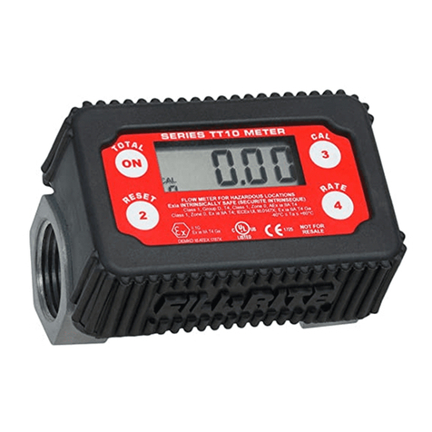
TT10A In-line Turbine Meter

1
1
Dear Tuthill Customer,
Thank you for buying a Tuthill product. Tuthill
represents a new age in transfer and measuring
equipment. This manual contains valuable
information about your new equipment and its
operating and service requirements. Please take
a few minutes to review this material carefully.
Tuthill’s mission is to provide fl uid handling systems
that deliver the most accurate, safe, convenient,
and economical transfer systems for users of
fuels.
If, for any reason, any of the products do not meet
your performance expectations,we want to hear
from you.
Your comments and suggestions are requested
and appreciated. Thank you again for buying a
Tuthill product. We look forward to serving you in
the future.
The Tuthill Team 1-800-634-2695
To ensure safe and effi cient operation, it is essential
to read and follow each of the following warnings
and precautions.
1. Fuels and Chemicals fl owing through the meter
may be harmful to your health. Use and disposal
of these products is controlled by federal, state,
or local laws and procedures.
2. Conform to fl uid manufacturer’s recommended
handling procedures when using product and
when cleaning meter.
3. Do not exceed an internal meter pressure of
50 PSI (3.5 Bar) for the TT10A models and
125 PSI (8.6 Bar) for the TT10P models.
4. Improper use or installation of this product can
cause serious bodily injury or death.
5. Ensure the piping and hoses connected to the
meter are properly grounded when metering or
using near fl ammable fl uids.
6. DO NOT install additional foot or check valves
without use of a pressure relief valve; otherwise
the meter may rupture.
7. To avoid build up of electrostatic discharge,
please clean with damp cloth only.
8. The meter body is made of aluminum alloy.
Avoid impact or fraction on meter body.
Safety Instructions
CAUTION!
Wear proper safety equipment when handling
hazardous fl uids.
TT10A (Fuels) Technical Information
Flow Ports 1" NPT or BSPP female inlet and
outlet ports
Flow Range 2 to 35 U.S. GPM / 7.6 to 132.5 LPM
Working 50 PSI (3.4 Bar)MAX UL
Pressure 300 PSI (20.7 Bar) Burst
Storage -40°F to 176°F (-40°C to 60°C)
Temperature (No Liquids)
Operating -40°F to 176°F (-40°C to 60°C)
Temperature
Measurement ±1.0% (After fi eld calibration)
Accuracy
Measurement ±0.30% (Batch sizes ≥ 2 Gallons)
Repeatability
Measurement Ounce, Pint, Quart, Liter, Gallon
Units
Totalizer 0 - 90,000,000 Units
Range
Batch Range 0.00 - 9999 Units (Blinks when Batch
exceeds 9999)
Wetted 304/316 Stainless Steel,
Materials Aluminum Acetal, Gold
Display -40°F to 176°F (-40°C to 60°C)
Power 2 approved alkaline batteries.
See battery replacement section
of the manual
Memory Meter totals and calibration are
preserved when replacing batteries
Safety Intrinsically safe electronics for use
in hazardous locations.

2
General Description
The TT10 Series Meters are electronic turbine meters
suitable for use in Hazardous Locations and extreme
temperatures.
The TT10 Meters feature advanced electronics that
eliminate false counts in high vibration and mobile
applications without sacrifi cing the ability to meter at
low fl ows.
The meter can store and display the current metered
amount (batch total), or cumulative metered amount
(totalizer) in any of fi ve user selectable units (ounces,
pints, quarts, liters, and gallons).
The meter may be easily adjusted for different fl uids by
selecting a calibration factor from one of 20 settings.
Power is supplied by two replaceable AA alkaline batteries.
Fluid / Viscosity Compatibility
The TT10A Series meters will handle most fuels with
viscosities in the range of 0.4 cSt to 79 cSt.
You may meter fl uids that exceed a viscosity of 79 cSt, but
accuracy will be limited to the calibration fl ow rate. Set the
meter for CAL 19 and follow the calibration described in
this manual.
If in doubt about compatibility of a specifi c fl uid, contact
the supplier of the fl uid to check for any adverse reactions
to the listed materials in the Technical Information section
of this manual.
Approved Fluids:
• Gasoline • Heptane
• Diesel • Mineral Spirits
• Kerosene • Non-potable
• Hexane fresh water
Installation
Installation Hints
Excess sealant tape or thread compound upstream
of the meter can break free and jam or impair the
rotor and cause meter failure. Use of an appropriate
amount of thread compound is the preferred
method of installation.
Use a compatible sealant tape or thread compound on all
threaded joints.
1. Determine correct direction for fl uid fl ow and point the
arrow on the underside of the meter body in that
direction. Installing the meter in the wrong direction
of fl ow will signifi cantly impact the performance of
the meter.
2
2. Thread the hose or pipe into ports until snug.
Be careful not to cross thread when starting
threads or over-tighten the meter.
Electronic Module Orientation
The Display can be oriented for right-to-left or
left-to-right fl ow.
1. Peel off the protective rubber boot and set aside.
2. Remove the 4 screws holding on the electronic
module using a T-20 Torx driver.
3. Remove the module and rotate 180°. Ensure that the
foam pad under the batteries is reinstalled correctly if
it falls out. This is critical to ensure the batteries are not
dislodged if the meter is exposed to rough handling.
4. Reinstall the 4 screws. They should be tight enough to
fully seat the module. The recommended installation
torque is 5-10 in-lb (0.6-1.1 Nm). Over-tightening may
crack the module.
5. Reinstall the protective rubber boot.
CAUTION!
When reinstalling the screws for the electronic
module, ensure the grounding tabs are captured
under the heads of the screws. This ensures proper
ground and protection against static discharge
when handling the meter.

3
Operational Functions
• Turns meter on.
• Displays accumulated total while pressed.
If the accumulated total is larger than
9999, the numbers will scroll across the
screen in groups of 4 digits.
When held for 3 seconds, it resets the current
total to zero. Also reverts to normal operating
mode when in CAL or FLSH mode.
When held for 3 seconds, it allows changes
to the calibration/fl uid factor displayed in
the bottom left corner. Repeated activation
will increment the number up to 19 and
then back to zero. When the desired number
is displayed, press button 2 to lock in the
new number and return to normal operation.
Please reference Table 1 for specifi cs.
When held for 3 seconds, the RATE icon is
displayed. The active fl ow rate will be dis-
played. Press button 4 again to resume
normal operation. The meter will continue
to count volume while fl ow rate is displayed.
NOTE
The meter display will automatically turn off after
30 seconds of inactivity to conserve batteries. It will
turn on when fl ow resumes or any button is pushed.
No data is lost during periods of inactivity.
Changing Units of Measure
The units of measure can be changed to ounces (OZ),
pints (PT), quarts (QT), gallons (GAL), or liters (LITER)
without recalibrating the meter.
1. Hold buttons 2 and 4 for three seconds. The display
will show the fi rmware version.
2. Press button 3 . The display will show the current unit.
3. To change units, press the ON button repeatedly until
the desired unit is displayed.
4. Press button 2 to lock in the selection. The display will
show the fi rmware version.
5. To return to normal operating mode press button 2
again.
6. The units selected will be displayed. Current or
accumulated total will be updated to refl ect the new
unit of measure.
3
The TT10 Series Meters provide 20 preset factors for
different fl uid types/viscosities.
Use of calibration factors is intended to provide the most
accurate metering solution for a specifi c fl uid. A CAL factor
of 0 is for use with the thinnest fl uids and increases for
higher viscosity fl uids.
1. Press and hold button 3 for 3 seconds. The current
dispensed count value will disappear and only the CAL
icon and the current value will be displayed.
2. Repeatedly pushing button 3 will increment the
number up to 19 and then back to zero.
3. After the desired fl uid factor has been selected, press
button 2 to lock in the fl uid factor and return the meter
to normal operating mode.
CAL Factors and viscosities shown in the table below are
for fl uids at 70°F / 21°C.
Cal 0 1 2 3 4 5 6 7 8 9
cSt
0.36
0.48
0.63
0.84
1.12
1.48
1.98
2.62
3.48
4.62
Fluid
Heptane
Gasoline
Water / DEF
Mineral Spirits
Kerosene
Diesel
B100
Cal 10 11 12 13 14 15 16 17 18 19
cSt
6.15
8.16
10.8
14.4
19.1
25.4
33.7
44.8
59.5
79.0
Fluid
Jet Fuel
Ethylene Glycol
Propylene glycol
10W-30 Oil / ATF
NOTE
Use of the CAL/Fluid factor is independent from
performing a calibration against a known volume.
The meter is calibrated at the factory, but
performing a fi eld calibration may further improve
meter accuracy.
Table 1: CAL Factor Table
Press Calibration/Fluid Type Factor (CAL)

4
Fluid Calibration
Fluid calibration requires a container of a known volume
at least 5 gallons or larger that is compatible with the fl uid
being metered.
A larger volume may be used and may improve calibration
accuracy, but do not exceed 99.99 units of measure.
NOTE
Before performing a fl uid calibration, ensure you
have selected the closest matching CAL/Fluid factor
to ensure the best meter accuracy.
1. Press the 2 & 4 buttons at the same time and hold
for 3 seconds. The display will show the fi rmware
version.
2. Press button 3 to enter calibration mode. The unit of
measure will be displayed.
3. Press button 3 . The display will read "FILL".
4. Now dispense fl uid into your container. "FILL" will blink
on the display when fl ow is detected.
5. After dispensing fl uid, press the ON button. The left
digit of the display will blink. ("00.00")
6. Press button 4 to increment the digit to the amount
of fl uid dispensed (example: "05.00"). Press the ON
button to move to the right. If you make a mistake,
press button 2 to start back at the left-most digit.
7. After number is loaded, press the ON button again
to accept the entered volume.
8. Display now shows the confi gured CAL factor.
9. Press the ON button again and the fi rmware version
will be displayed.
10. Press the 2 button again to return to normal
operating mode.
NOTE
If the value entered is out of an acceptable range,
the display will read "Err0" and the meter will revert
to the previous settings. See Troubleshooting Guide
for more information.
TIP
If you are metering in ounces, pints, or quarts, it
may be easier to switch the meter to a larger unit of
measure such as gallons or liters for the calibration
process and then change back to the desired unit of
measure.
Flush Mode (FLSH)
Use of Flush mode allows you to fl ush the meter without
adding volume to the meter totals. This is useful when
fl ushing the meter for storage or switching between
different liquids and you want to maintain accurate totals.
1. Hold buttons 3 and 4 for 3 seconds. The Meter will
display "FLSH".
2. Press button 2 to return to normal operating mode.
Reset Accumulated Total
1. Press and hold buttons 2 and 4 for 3 seconds.
The current fi rmware version will be displayed.
2. Press the ON button to display the accumulated total.
If over 9999 units, the accumulated total will scroll
across the display.
3. Hold buttons ON and 4 together for 5 seconds to
reset the accumulated total.
4. Press the 2 button twice to return to normal operating
mode.
K-Factor Check
You can check the internal calibration factor for the meter.
The displayed value is the number of sensor counts per
selected unit of measure and CAL/Fluid factor. The factory
may ask you for this value if troubleshooting the Meter.
1. Hold buttons 3 and 4 for 3 seconds. The Meter will
display "FLSH".
2. Press and hold buttons ON and 3 together. The
number of counts per unit of measure will be displayed.
3. Press button 2 to return to normal operating mode.
Battery Replacement
Batteries should be replaced when the LOW battery
icon begins to blink on the display. The meter totals,
confi guration, and calibration are preserved while the
batteries are being replaced, so there is no need to
recalibrate afterwards.
WARNING!
When replacing batteries, make the area safe of
explosive vapors, or move the meter electronics to
a safe area before replacing them.
4

5
The batteries are accessed by removing the display as
described in the section showing how to rotate the display.
The Battery Foam may be stuck to the batteries. Carefully
remove it and reinstall at assembly. The Battery Foam
protects the batteries and prevents them from becoming
dislodged if the meter is handled roughly.
Pay attention to the polarity of the batteries as marked
inside the battery holder. The meter will not operate if the
batteries are installed incorrectly and damage may occur.
5
WARNING!
To reduce the risk of explosion DO NOT mix old
batteries with new batteries, or mix batteries of
different manufacturers.
Batteries may ONLY be replaced with the following:
• Duracell MN1500 • Energizer E91
• Duracell QU1500
Maintenance and Storage
If the meter will be stored for an extended period of time
without use and is being used with a fl uid that may leave
a residue, it should be fl ushed with a compatible fl uid to
prevent sticking and binding of the turbine assembly.
The exterior of the meter may be wiped down with a mild
water based detergent and damp cloth to clean the display.
Do not use a power washer to clean the meter.
IMPORTANT!
Use of compressed air WILL cause permanent
damage to the meter. Always use a gentle stream
of compatible fl uid to rinse the interior of the meter.
Regulatory
Safety Testing Approvals
The Fill-Rite TT10 Series meters have been tested
for compliance to the standards set forth by
Underwriters Laboratories (UL), UL Canada, ATEX,
and other testing organizations. To determine which
specifi c compliances apply to your particular
meter, refer to the faceplate for information and
compliance logos.
FLOW METER FOR HAZARDOUS LOCATIONS
Exia INTRINSICALLY SAFE (SECURITE
INTRINSEQUE)
Class I, Group D, T4; Class I, Zone 0, AEx ia IIA T4
Ex ia IIA T4; IECEx UL 16.0147X; Ex ia IIA T4 Ga;
-40°C < Ta < +60°C
CE Certifi cation Information
The TT10 Series meters bearing the CE mark
have been certifi ed to the following European
directives:
2011/65/EU: Restriction of the use of certain
hazardous substances in electrical and electronic
equipment. 2014/30/EU: Electromagnetic
Compatibility
The following standards were used to test and
show compliance:
Emissions
EN 55011:2009/A1:2010 Group 1, Class B, Industrial,
Scientifi c, and Medical (ISM) Equipment
Immunity
IEC 61000-4-8: 2010 Magnetic Field
EN 60079-0: 2012 + A11:2013
IEC 60079 Edition 6
EN 60079-11: 2012
IEC 60079-11 Edition 6
UL60079-0 Sixth Edition
UL60079-11 Sixth Edition
CAN/CSA - C22.2 No 157-92
CAN/CSA - C22.2 No 60079-0:2014
CAN/CSA - C22.2 No 60079-11:2015
UL 25
ULC/ORD-C25
II 1G
Ex ia IIA T4 Ga
DEMKO 16 ATEX 1787X

6
6
Table 2: Troubleshooting Guide
Problem Possible Cause Solution
• Dead batteries • Replace batteries Seal to electronics is
Meter won't turn on • Damaged electronics • Replace the meter broken if the display is
removed or punctured.
Counter has exceeded Reset display to zero by Meter will continue to
Flashing decimals 9999 units pressing and holding button operate normally.
2
Flashing BAT Icon Low batteries Replace batteries See battery
replacement section
Leaking fl uid at the • Need thread sealant • Add sealant to the joint
inlet / outlet port • Cross-threaded port • Replace the meter
Fluid fl ows; meter • Turbine is jammed • Flush the meter
won’t count • Meter failure • Replace the meter
• Air is in system • Ensure meter is full of Meter will count air. Fluid
liquid at all times viscosities will change
Meter reading is • Meter is installed backwards • Correct fl ow direction with temperature
not correct of the meter
• Fluid viscosity changed
• Wrong CAL/fl uid factor • Use correct CAL/factor
• Poor calibration • Recalibrate
• Air is in the system • Ensure meter is full of 40 mesh minimum inlet
liquid at all times screen
• Meter is installed backwards • Correct fl ow direction
Meter is not of the meter
consistent / repeatable • Particulates in the fl uid • Flush the meter
• Turbine is gummed up • Put a screen in front of meter
• Operating outside fl ow • Operate within fl ow range
range of meter of meter
• Calibration Error • Recalibrate with a more Indicates fl uid calibration
accurate container is out of acceptable
• Meter may have • Replace the meter range. Volumetric
Err0 excessive wear container may not be
accurate or there is air
in the system. Meter may
have excessive wear
Damaged electronics or • Press and hold button
Software error 2 to reset counter and
Err1 then recalibrate meter
• Replace the meter
Bad eeprom Replace the meter Meter still functions but
Err2 totals and calibration
will be lost if batteries
are removed.

7
LIMITED WARRANTY POLICY
Revision Date: August 1, 2014
Fill-Rite and Sotera Products
Tuthill Transfer Systems ("Manufacturer") warrants each consumer buyer of its products ("Buyer")
from date of sale that goods of its manufacture ("Goods") shall be free from defects of materials
and workmanship.
The duration of the warranty is as follows:
End users must contact the place where they purchased the product to process a warranty. “Place
of purchase” is defi ned as any authorized TTS Distributor, including any and all retail stores, mail
order houses, catalogue houses, on-line stores, commercial distributors.
Manufacturer’s sole obligation under the foregoing warranties will be limited to either – at
Manufacturer’s option – replacing defective goods (subject to limitations hereinafter provided)
or refunding the purchase price for such Goods theretofore paid by the buyer, and Buyers
exclusive remedy for breach of any such warranties will be enforcement of such obligations of
the Manufacturer. If the Manufacturer so requests the return of such Goods, the Goods will be
redelivered to the manufacturer in accordance with Manufacturer’s instructions FOB Factory.
The remedies contained herein shall constitute the sole recourse of the Buyer against the
Manufacturer for breach of warranty. IN NO EVENT SHALL THE MANUFACTURER'S LIABILITY
FOR ANY CLAIM FOR DAMAGES ARISING OUT OF THE MANUFACTURE, SALE, DELIVERY,
OR USE OF THE GOODS EXCEED THE PURCHASE PRICE.
The foregoing warranties will not extend to goods subject to misuse, neglect, accident, improper
installation or maintenance, or have been repaired by anyone other than the Manufacturer or
its authorized representative. THE FOREGOING WARRANTIES ARE EXCLUSIVE AND IN
LIEU OF ALL OTHER WARRANTIES OF MERCHANTABILITY, FITNESS FOR PURPOSE OF
ANY OTHER TYPE, WHETHER EXPRESSED OR IMPLIED. No person may vary the forgoing
warranties or remedies, except in writing signed by a duly authorized offi cer of the Manufacturer.
The Buyer's acceptance of delivery of the Goods constitutes acceptance of the foregoing warranties
and remedies, and all conditions and limitations thereof.
From Date
of Sale
Not to Exceed the Following
Period from Date of
Manufacture
Product Series
Five Years 60 Months SP100 Series Pumps 400 Series Pumps
Two Years 27 Months Heavy Duty Pumps and
Meters,
820, 825, and 850 Meters
Cabinet Pumps,
Cabinet Meters, TN
Meters, TM Meters,
TS Meters
One Year 15 Months Standard Duty Pumps and
Meters, 1600 Pumps
Accessories
Parts
* proof of purchase should be presented to place of purchase
** see Appendix for defi nition of “Heavy Duty” and “Standard Duty” products
7

Other manuals for FILL-RITE TT10A
2
Table of contents
Other Tuthill Measuring Instrument manuals

Tuthill
Tuthill Sotera TS06AS83 Guide

Tuthill
Tuthill TT10P Use and care manual

Tuthill
Tuthill Fill-Rite 900 Series Use and care manual

Tuthill
Tuthill FILL-RITE 900DB Use and care manual

Tuthill
Tuthill Fill-Rite 900 Series Use and care manual

Tuthill
Tuthill FILL-RITE TT10A Use and care manual

Tuthill
Tuthill Sotera 900 Series Use and care manual

Tuthill
Tuthill FILL-RITE 820 Operating manual

Tuthill
Tuthill FILL-RITE TN700 Series Use and care manual

Tuthill
Tuthill FILL-RITE TT10A Use and care manual