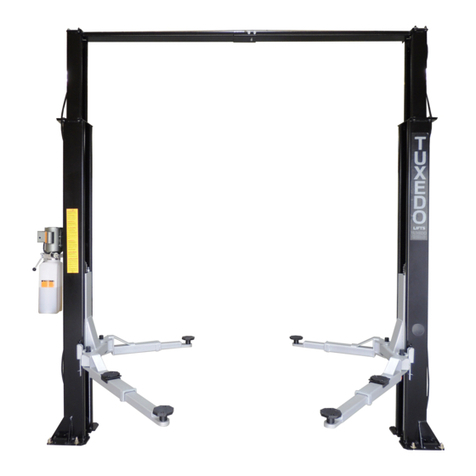
Tuxedo PL6K User manual

PL6K
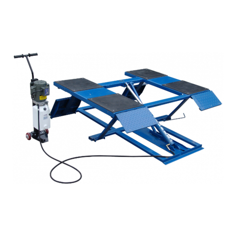
6600 POUND CAPACITY LOW RISE PIT
Installation and Operation Manual
REV A-062813


2
6,000 POUND CAPACITY LOW RISE PIT LIFT
This instruction manual has been prepared especially for you. Your new lift is the product of over
20 years of continuous research, testing and development; it is one of the most technically
advanced liftson the market today.
READ THIS ENTIRE MANUAL BEFORE INSTALLATION & OPERATION
BEGINS.
RECORD HERE THE LIFT AND POWER UNIT INFORMATION WHICH IS LOCATED ON THE
SERIAL NUMBER DATA PLATES ON THE LIFT AND ON THE POWER UNIT
Power Unit Model # _____________
Power Unit Date Of Mfg. _____________
Power Unit Serial # _____________
This information is required when calling for parts or warranty issues.

1905 N Main St Suite C, Cleburne, TX 76033
Ph 817-558-9337 Fax 817-558-9740
TUXEDO DISTRIBUTORS LIMITED WARRANTY
Structural Warranty:
The following parts and structural components carry a five year warranty:
Columns Top Rails Beams Uprights Arms Swivel Pins
Legs Carriages Trac s Cross Rails Overhead Beams
Limited One-Year Warranty:
Tuxedo Distributors, LLC (“Tuxedo”) offers a limited one-year warranty to the original purchaser of Tuxedo Lifts
and Wheel Service in the United States and Canada. Tuxedo will replace, without charge, any part found defective
in materials or wor manship under normal use, for a period of one year after purchase. The purchaser is
responsible for all shipping charges. This warranty does not apply to equipment that has been improperly installed
or altered or that has not been operated or maintained according to specifications.
Other Limitations:
This warranty does not cover:
1. Parts needed for normal maintenance
2. Wear parts, including but not limited to cables, rub bloc s, chains, rubber pads and pulleys
3. Replacement of lift and tire changer cylinders after the first 30 days. A seal it and installation
instructions will be sent for repairs thereafter.
4. On-site labor
Upon receipt, the customer must visually inspect the equipment for any potential freight damage before signing
clear on the shipping receipt. Freight damage is not considered a warranty issue and therefore must be noted for
any potential recovery with the shipping company.
The customer is required to notify Tuxedo of any missing parts within 72 hours. Timely notification must be
received to be covered under warranty.
Tuxedo will replace any defective part under warranty at no charge as soon as such parts become available from
the manufacturer. No guarantee is given as to the immediate availability of replacement parts.
Tuxedo reserves the right to ma e improvements and/or design changes to its without any obligation to previously
sold, assembled or fabricated equipment.
There is no other express warranty on the Tuxedo lifts and this warranty is exclusive of and in lieu of all other
warranties, expressed or implied, including all warranties of merchantability and fitness for a particular purpose.
To the fullest extent allowed by law, Tuxedo shall not be liable for loss of use, cost of cover, lost profits,
inconvenience, lost time, commercial loss or other incidental or consequential damages.
This Limited Warranty is granted to the original purchaser only and is not transferable or assignable.
Some states do not allow exclusion or limitation of consequential damages or how long an implied warranty lasts,
so the above limitations and exclusions may not apply. This warranty gives you specific legal rights and you may
have other rights, which may vary from state to state

6
IMPORTANT NOTICE
Do not attempt to install this lift if you have never been
trained on basic automotive lift installation procedures.
Never attempt to lift components without proper lifting
tools such as forklift or cranes. Stay clear of any moving
parts that can fall and cause injury. These instructions
must be followed to insure proper installation and
operation of your lift. Failure to comply with these
instructions can result in serious bodily harm and void
product warranty. Manufacturer will assume no liability
for loss or damage of any kind, expressed or implied
resulting from improper installation or use of this
product.
PLEASE READ ENTIRE MANUAL
PRIOR TO INSTALLATION.
DEFINITIONS OF HAZARD LEVELS
Identify the hazard levels used in this manual with the
following definitions and signal words:
DANGER!
Watch for this symbol: It Means: Immediate hazards
which will result in severe personal injury or death.
WARNING!
Watch for this symbol: It Means: Hazards or unsafe
practices which could result in severe personal injury or
death.
CAUTION!
Watch for this symbol: It Means: Hazards or unsafe
practices which may result in minor personal injury or
product or property damage.
OWNER’S RESPONSIBILITY
To maintain the lift and user safety, the responsibility of
the owner is to read and follow these instructions
Follow all installation and operation instructions.
Make sure installation conforms to all applicable Local,
State, and Federal Codes, Rules, and Regulations;
such as State and Federal OSHA Regulations and
Electrical Codes.
Carefully check the lift for correct initial function.
Read and follow the safety instructions. Keep them
readily available for machine operators.
Make certain all operators are properly trained, know
how to safely and correctly operate the unit, and are
properly supervised.
Allow unit operation only with all parts in place and
operating safely.
Carefully inspect the unit on a regular basis and
perform all maintenance as required.
Service and maintain the unit only with authorized or
approved replacement parts.
Keep all instructions permanently with the unit and all
decal’s on the unit clean and visible.
BEFORE YOU BEGIN
NOTIFY THE CARRIER AT ONCE if any hidden loss or
damage is discovered after receipt and request the carrier
to make an inspection. If the carrier will not do so, prepare
a signed statement to the effect that you have notified the
carrier (on a specific date) and that the carrier has failed to
comply with your request.
IT IS DIFFICULT TO COLLECT FOR LOSS OR
DAMAGE AFTER YOU HAVE GIVEN THE CARRIER A
CLEAR RECEIPT. Support claim with copies of the bill of
lading, freight bill, invoice, and photographs, if available.
Our willingness to assist in helping you process your claim
does not make us responsible for collection of claims or
replacement of lost or damaged materials.

7
TABLE OF CONTENTS
Contents Page No.
Serial Number . . . . . . . . . . . . . . . . . . . . . . . . . . .. . . . . . . . . . . . . . . . . . . . . . . . . . . . . . . . . . .. . . . . .. . . . . . . . .2
Warranty . . . . . . . . . . . . . . . . . . . . . . . . . . . . . . . . . . . . . . . . . . . . . . . . . . . . . . . . . . . . . . . .. . . . . .. . . . . . . . .3
Definitions of Hazard Levels. . . . . . . . . . . . . . . . . . . . . . . . . . . . . . . . . . . . . . . . . . . . . . . .. . . . . . .. . . . . . . . . . 6
Owner’s Responsibility . . . . . . . . . . . . . . . . . . . . . . . . . . . . . . . . . . . . . . . . . . . .. . . . . . . . . . . . . . . . . . . . . . . . 6
Before You Begin. . . . . . . . . . . . . . . . . . . . . . . . . . . .. . . . . . . . . . . . . . . . . . . . . . . . . . . . . . . . . . . . . . . . . . . . . 6
Installer / Operator Agreement/ Protective Equipment. . . . . . . . . . . . . . . . . . . . . . . . . . . . . .. . . . . . . . . . . . . . . 8
Introduction. . . . . . . . . . . . . . . . . . . . . . . . . . . . . . . . . . . . . . . . . . . . . . . . . . . . . . . . . . .. . . . . . . . . . . . . . . . . . 9
Safety / Warning Instructions . . . . . . . . . . . . . . . . . . . . . . . . . . . . .. . . . . . . . . . . . . . . . . . . . . . . . . . . . . . . . . . 9
Tools Required. . . . . . . . . . . . . . . . . . . . . . . . . . . . . . . . . . . . . . . . . . . .. . . . . . . . . . . . . . . . . . . . . . . . . . . . . . . 10
Step 1 / Selecting Site . . . . . . . . . . . . . . . . . . . . . . . . . . . . . . . . . . . . . . .. . . . . . . . . . . . . . . . . . . . . . . . . . . . . . 10
Step 2 / Floor Requirements . . . . . . . . . . . . . . . . . . . . . . . . . . . . . . . . . . . . . . . . . . . . . . . . . . . . . . . . . . . . . . . .10
Concrete Specifications. . . . . . . . . . . . . . . . . . . . . . . . . . . . . . . . . . . . . . . . . . . . . . . . . . . . . . . . . . . . . . . . . . . .10
Packing List . . . . . . . . . . . . . . . . . . . . . . . . . . . . . . . . . . . . . . . . . . . . . . . . . . . . . . . . . . . . . . . . . . . . . . . . . . . .11
Main Assembly View / Description of Parts . . . . . . . . . . . . . . . . . . . . . . . . . . . . . . . . . . . . . . . .. . . . . . . . . . . . .12
Floor Plan / Specifications . . . . . . . . . . . . . . . . . . . . . . . . . . . . . . . . . . . . . . . . . . . . . . . . . . . . . . .. . . . . . . . . . .12
Step 3 / Locating Lift . . . . . . . . . . . . . . . . . . . . . . . . . . . . . . . . . . . . . . . . . . . . . . . . . . . . . . . . . . . . .. . . . . . . . . 14
Step 4 / Power Unit Location. . . . . . . . . . . . .. . . . . . . . . . . . . . . . . . . . . . . . . . . . . . . . . . . . . . . . . . . . . . . . . . . 15
Step 5 / Flow Divider/ Hydraulic Hose Installation. . . . . . . . . . . . . . . . . . . . . . . . . . . . . . . . . . . . . . . . . . . . .15-16
Step 6 / Power Unit Installation . . . . . . . . . . . . . . . . . . . . . . . . . . . . . . . . . . . . . . . . . . . . . . . . . .. . . . . . . . .16-17
Step 7 / Routing Air Lines . . . . . . . . . . . . . . . . . . . . . . . . . . . . . . . . . . . . . . . . . . . . . . . . . . . . . . . . . . . . . . . . . .18
Step 8 / Anchoring Lift Assemblies . . . . . . . . . . . . . . . . . . . . . . . . . . . . . . . . . . . . . . . . . . . . . . . . . . . . . . . . . . .19
Step 9 / Bleeding . . . . . . . . . . . . . . . . . . . . . . . . . . . . . . . . . . . . . . . . . . . . . . . . . . . . . . . . . . . . .. . . . . . . . . . . .19
Step 10 / Lift Start Up / Final Adjustments . . . . . . . . . . . . . . . . . . . . . . . . . . . . . . . . . . . . . . . . . . . . . . . . . . . . .20
Step 11 / Operation/ Maintenance . . . . . . . . . . . . . . . . . . . . . . . . . . . . . . . . . . . . . . . . . . . . . . . . . . . . .. . . .21-26
Troubleshooting Guide . . . . . . . . . . . . . . . . .. . . . . . . . . . . . . . . . . . . . . . . . . . . . . . . . . . . . . . . . . . . . ... . . 27-30
Main Parts Listing . . . . . . . . . . . . . . . . . . . . . . . . . . . . . . . . . . . . . . . . . . . . . . . . . . . . . . . . . . . . . . . . . . . . 31-33
Maintenance Records. . . . . . . . . . . . . . . . . . . . . . . . . . . . . . . . . . . . . . . . . . . . . . . . . . . . . . . . . . . . . . . . .. 34
Installation Agreement . . . . . . . . . . . . . . . . . . . . . . . . . . . . . . . . . . . . . . . . . . . . . . . . . . . . . . . . . . . . . . . . . . . .35

8
INSTALLER / OPERATOR PLEASE
READ AND FULLY UNDERSTAND. BY
PROCEEDING YOU AGREE TO THE
FOLLOWING.
I have visually inspected the site where the lift is to
be installed and verified the concrete to be in good
condition and free of cracks or other defects. I understand
that installing a lift on cracked or defective concrete could
cause lift failure resulting in personal injury or death.
I understand that a level floor is required for proper
installation and level lifting.
I understand that I am responsible if my floor is of
questionable slope and that I will be responsible for all
charges related to pouring a new level concrete slab if
required and any charges.
I understand that the lifts are supplied with concrete
fasteners meeting the criteria of the American National
Standard “Automotive Lifts - Safety Requirements for
Construction, Testing, and Validation” ANSI/ALI ALCTV-
2006, and that I will be responsible for all charges related to
any special regional structural and/or seismic anchoring
requirements specified by any other agencies and/or codes
such as the Uniform Building Code (UBC) and/or
International Building Code (IBC).
I will assume full responsibility for the concrete floor
and condition thereof, now or later, where the above
equipment model(s) are to be installed. Failure to follow
danger, warning, and caution instructions may lead to
serious personal injury or death to operator or bystander or
damage to property.
I understand that this lift is designed to be installed
in indoor locations only. Failure to follow installation
instructions may lead to serious personal injury or death to
operator or bystander or damage to property or lift.
Failure to follow danger, warning, and caution instructions
may lead to serious personal injury or death to operator or
bystander or damage to property.
Please read entire manual prior to installation. Do not
operate this machine until you read and understand all the
dangers, warnings and cautions in this manual. For
additional copies or further information, contact your
distributor.
INSTALLER / OPERATOR PROTECTIVE
EQUIPMENT
Personal protective equipment helps make installation and
operation safer, however, does not take the place of safe
operating practices. Always wear durable work clothing
during any installation and/or service activity. Shop aprons
or shop coats may also be worn, however loose fitting
clothing should be avoided. Tight fitting leather gloves are
recommended to protect technician hands when handling
parts. Sturdy leather work shoes with steel toes and oil
resistant soles should be used by all service personnel to
help prevent injury during typical installation and operation
activities.
Eye protection is essential during
installation and operation activities. Safety
glasses with side shields, goggles, or face
shields are acceptable. Back belts provide
support during lifting activities and are also
helpful in providing worker protection.
Consideration should also be given to the use of hearing
protection if service activity is performed in an enclosed
area, or if noise levels are high.
THIS SYMBOL POINTS OUT IMPORTANT SAFETY INSTRUCTIONS WHICH IF NOT FOLLOWED
COULD ENDANGER THE PERSONAL SAFETY AND/OR PROPERTY OR YOURSELF AND OTHERS
AND CAN CAUSE PERSONAL INJURY OR DEATH. READ AND FOLLOW ALL INSTRUCTIONS IN
THIS MANUAL BEFORE ATTEMPTING TO OPERATE THIS MACHINE.
9
INTRODUCTION
1. Carefully remove the crating and packing materials.
CAUTION! Be careful when cutting steel banding
material as items may become loose and fall causing
personal harm or injury.
2. Check the voltage, phase and proper amperage
requirements for the motor shown on the motor plate.
Wiring should be performed by a certified electrician
only.
IMPORTANT SAFETY INSTRUCTIONS
Read these safety instructions entirely!
IMPORTANT NOTICE!
Do not attempt to install this lift if you have never been trained on basic automotive lift installation procedures.
Never attempt to lift components without proper lifting tools such as forklift or cranes. Stay clear of any moving
parts that can fall and cause injury.
1. READ AND UNDERSTAND all safety warning
procedures before operating lift.
2. KEEP HANDS AND FEET CLEAR. Remove hands
and feet from any moving parts. Keep feet clear of
lift when lowering. Avoid pinch points.
3. KEEP WORK AREA CLEAN. Cluttered work areas
invite injuries.
4. Consider work area environment. Do not expose
equipment to rain. DO NOT use in damp or wet
locations. Keep area well lighted.
5. ONLY TRAINED OPERATORS should operate this
lift. All non-trained personnel should be kept away
from work area. Never let non-trained personnel
come in contact with, or operate lift.
6. USE LIFT CORRECTLY. Use lift in the proper
manner. Never use lifting adapters other than what
is approved by the manufacturer.
7. DO NOT override self-closing lift controls.
8. REMAIN CLEAR of lift when raising or lowering
vehicle.
9. CLEAR AREA if vehicle is in danger of falling.
10. ALWAYS INSURE that the safeties are engaged
before any attempt is made to work on or near
vehicle.
11. DRESS PROPERLY. Non-skid steel-toe
footwear is recommended when operating lift.
12. GUARD AGAINST ELECTRIC SHOCK.
This lift must be grounded while in
use to protect the operator from
electric shock. Never connect the
green power cord wire to a live
terminal. This is for ground only.
13.DANGER! The power unit used on
this lift contains high voltage.
Disconnect power at the receptacle
before performing any electrical
repairs. Secure plug so that it cannot
be accidentally plugged in during
service.
14. WARNING! RISK OF EXPLOSION.
This equipment has internal arcing
or sparking parts which should not
be exposed to flammable vapors.
This machine should not be located
in a recessed area or below floor
level.
15. MAINTAIN WITH CARE. Keep lift clean for
better and safer performance. Follow manual for
proper lubrication and maintenance instructions.
Keep control handles and/or buttons dry, clean
and free from grease and oil.
16. STAY ALERT. Watch what you are doing. Use
common sense. Be aware.
17. CHECK FOR DAMAGED PARTS. Check for
alignment of moving parts, breakage of parts or any
condition that may affect its operation. Do not use lift if
any component is broken or damaged.
18. NEVER remove safety related components from the
lift. Do not use lift if safety related components are
damaged or missing.

10
TOOLS REQUIRED
Rotary Hammer Drill Or Similar
3/4” ; 1 1/4” Masonry Bits
Hammer
4 Foot Level
Open-End Wrench Set: 1/2””,15/16” - 1-1/8”
Socket And Ratchet Set: 1-1/8”
Medium Crescent Wrench
Crow Bar
Chalk Line
Medium Flat Screwdriver
Tape Measure: 25 Foot Suggested
NOTE: An air supply (30 PSI Min / 3 CFM Min.) will be required for the safety-lock mechanisms. See Step 11.
IMPORTANT NOTICE!
These instructions must be followed to insure proper installation and operation of your lift.
Failure to comply with these instructions can result in serious bodily harm and void product warranty.
Manufacturer will assume no liability for loss or damage of any kind, expressed or implied resulting
from improper installation or use of this product.
PLEASE READ ENTIRE MANUAL PRIOR TO INSTALLATION!
STEP 1
(Selecting Site)
Before installing your new lift, check the following.
1. LIFT LOCATION: Always use architects plans when
available. Check layout dimension against floor plan
requirements making sure that adequate space is
available.
2. OVERHEAD OBSTRUCTIONS: The area where the lift
will be located should be free of overhead obstructions
such as heaters, building supports, electrical lines etc.
3. DEFECTIVE FLOOR: Visually inspect the site where
the lift is to be installed and check for cracked or
defective concrete.
4. OPERATING TEMPERATURE. Operate lift only
between temperatures of 5° -40°C (41° -104° F.)
5. Lift is designed for INDOOR INSTALLATION ONLY.
STEP 2
(Floor Requirements)
This lift must be installed on a solid level concrete floor with
no more than 3-degrees of slope. Failure to do so could
cause personal injury or death.
A level floor is suggested for proper use and installation
and level lifting. If a floor is of questionable slope,
consider a survey of the site and/or the possibility of
pouring a new level concrete slab.
DO NOT install or use this lift on any asphalt
surface or any surface other than concrete.
DO NOT install or use this lift on expansion seams
or on cracked or defective concrete.
DO NOT install or use this lift on a second/elevated
floor without first consulting building architect.
DO NOT install or use this lift outdoors.
CONCRETE SPECIFICATIONS
The min. thickness of the concrete is 4” for this lift.
DANGER
This lift MUST be installed on 3000PSI concrete only
conforming to the minimum requirements shown above.
New concrete must be adequately cured by at least
28daysminimum.
!IMPORTANT NOTE:
This lift is supplied with installation instructions and concrete fasteners meeting the criteria as prescribed by the
American National Standard "Automotive Lifts - Safety Requirements for Construction, Testing, and Validation"
ANSI/ALI ALCTV-2006. Lift buyers are responsible for any special regional structural and/or seismic anchoring
requirements specified by any other agencies and/or codes such as the Uniform Building Code (UBC)and/or
International Building Code (IBC).
CAUTION!

11
PACKING LIST
When removing the lift from shipping pallet / angles pay close attention as
the lift assemblies can slide and can cause injury.
Prior to removing any strapping or shipping bolts make sure the lift is held
securely by a fork lift or some other heavy lifting devise.
CAUTION!
This lift should be installed by qualified lift installers only who are familiar with this
particular lift model and the requirements thereof. The frame on this lift MUST NOT
be twisted, bent or misaligned by un-level floors or improper anchoring.
Misalignment may cause damage to the lift.

12
Main Assembly View
Floor plan
NOTE:
The maximum recommended width between pads is 38”. Consult the factory for applications that require
installations wider than 38”.

13
Lift size
Basic Specification
Description Capacity Lifting Time Overall Height Platform Width Overall Length
Low Rise Pit Lift 3.0 ton
6000lbs
( about )
35 Sec
4 3/16” -- 26 3/16”
107-- 665mm
18”
457 mm
83 1/4”
2114mm

14
Fig. 3.1
STEP 3 (Locating Unit)
NOTE:
The maximum recommended width between pads is
38”. Consult the factory for applications that require
installations wider than 38”.
1. Before selecting an installation site, check for
proper clearance and/or obstructions. (See Fig
3.1)
2. Remember that the lift moves rearward
approximately 14” when raised. (See Fig 3.2)
Fig.2.3
3. Always consult the building engineer before
installing this lift to make sure the floor is capable
of sustaining the load.
4. After selecting a site, place each unit in position.
The Cylinders MUST be placed towards the inside.
(See Fig 3.3)
Fig.3.3
5. It may be necessary to remove the tire rail
adjacent to the lift pad and overhang the edge of
the rail to maintain the 36”- 38” recommended
width between pads.
6. Each lift pad can overhang the edge of the pit a
maximum of two inches on each side as long as
the inside anchor bolt can be installed properly.
Tire Rail

15
STEP 4 (Locating Power Unit)
1. Select a site for the Power Unit so that operators
have a full unobstructed view of the lift.
2. It is recommended that the Hydraulic Hose and Air
Safety Line for the lift be routed through the floor at
the base of the Power Unit, so check for routing
clearances.
3. Using the Power Unit Stand as a template, mark the
locations of the two anchor bolt holes.
4. Drill two holes 3/4” x 4” deep in concrete floor.
5. Remove all dust from hole.
6. Install Anchors as shown below. (See Fig. 4.2)
7. Secure Power Unit Stand to the floor using two
3/4” anchor bolts supplied.
8. Attach Power Unit to Stand using four 5/16” hex
bolts and nylon nuts supplied. NOTE: Motor must
be at least 18” above floor.
9. Install the Air Safety Valve “Z ”bracket on the
upper left mounting hole of the Power Unit Stand.
STEP 5
(Flow Divider / Hydraulic Hose Installation)
1. Secure the Hydraulic Flow Divider to a permanent
wall or fixture (usually below grade) in an area that
will allow the Power Hoses (the two hoses that are
installed at the lift Cylinders) to be equal length.
(See Fig 5.1)
It may be necessary to add hose extensions to
accommodate installation. If so, keep the power hoses
as close to equal length as possible to provide equal
pressure and lifting.

16
2. Install the 90 Degree Hydraulic Fitting in the pressure
port of the Power Unit. The pressure port is covered
with a plastic plug. Use teflon tape on pipe fittings
ONLY.
3. After the fitting is installed correctly, connect the 140”
Hydraulic Hose making sure to not over-tighten.
(For below grade hose installations a 1-1/4” hole should
be drilled through the floor at the base of the Power
Unit so the hose can be routed below grade.)
4. Connect the other end of the Power Unit Hose to the
fitting marked “IN” on the Flow Divider. (See Fig 5.1)
5. Connect the two remaining equal length Hoses to
the Flow Divider. (See Fig 5.1)
3/8” I.D. hydraulic tubing / hose may be used rather
than the hose provided as long as it is rated for 3,000
PSI operating pressure with a 12,000 PSI burst.
STEP 6 (Power Unit Installation)
1. Have a certified electrician run the power supply to
motor. Refer to the data plate found on the motor
for proper power supply and wire size.
NOTE: The standard power unit can be run on either
110V or 220V. It is already wired for 110V and
equipped with a 3-wire power cord with grounding
plug. For optional 220V hook up, follow the wiring
instructions as shown on the motor data plate. See
electrical data below.
Line Voltage Running Amps Circuit Breaker
110/115V 11.6 25A
208V 6.4 30A
230V 5.8 30A

17
2. Fill the reservoir with 10 WT. HYDRAULIC OIL
OR DEXRON TYPE III ATF, approximately 6.5
quarts. Make sure the funnel used to fill the power
unit is clean.
3. The standard power unit for your lift is 110 volt, 60HZ,
single phase. All wiring must be performed by a
certified electrician only. SEE WIRING
INSTRUCTIONS AFFIXED TO MOTOR FOR
PROPER WIRING INSTRUCTIONS.

18
STEP 7
(Routing Air Lines)
Connect the Air Safety Cylinders to the Air Safety Valve using the Tee Fitting and the Airline. Route the air line as
shown below making sure to position the push button air valve with the INLET facing towards the AIR SOURCE and
the OUTLET facing towards the lift. A filter/regulator/lubricator must be installed on air supply at lift. Failure to do so will
void the warranty. Cut the provided 1/4” air line tubing with a sharp blade to lengths as required. Tubing must be cut
square with no burrs.
Note: To assemble air line tubing into fitting, use firm, manual pressure to push tubing into the fitting until it bottoms out.
To remove air line tubing from the fitting, hold push sleeve in (against fitting) and, at the same time, pull out on tubing.
Pay careful attention to keep air line clear of any pinch points. Improper assembly may result in safety lock failure.
Note: An air supply (minimum: 30 psi / 3 CFM) is required for the safety-lock mechanisms to disengage. It is solely the
responsibility of the end-user to provide, install and maintain the air supply.
AIR PRESSURE SHOULD BE REGULATED TO 125 PSI MAX. (See Fig. 7.1)

19
STEP 8
(Anchoring the Lift Assemblies)
IMPORTANT NOTE:
This lift is supplied with installation instructions and
concrete fasteners meeting the criteria as
prescribed by the American National Standard
"Automotive Lifts - Safety Requirements for
Construction, Testing, and Validation" ANSI/ALI
ALCTV-2006. Lift buyers are responsible for any
special regional structural and/or seismic anchoring
requirements specified by any other agencies
and/or codes such as the Uniform Building Code
(UBC)and/or International Building Code (IBC).
NOTE:
For “pre-fab” or steel grate floors, check with the
building engineer for mounting suggestions. It may
be necessary to install all-thread rods through floor
and secure above and below.
1. Before anchoring lift to the floor, make sure the
location is satisfactory. Refer to Section 3.
2. Locate the six anchor bolt holes in the Lift Base
Frame. (See Fig 8.1)
NOTE: The lift must be elevated prior to drilling holes.
3. Using a 3/4” concrete bit, drill six holes on each pad
5” deep using the holes in the frame as a guide.
(See Fig 8.2)
4. Using Compressed air or vacuum, remove all excess
dust from holes, then install the anchor bolts. (See
Fig 8.3)
5. Tighten the anchor bolts 2-3 turnsusing an
open end wrench or manual ratchet only. DO
NOT use an impact wrench to tighten concrete
anchors.(See Fig 8.4 )
STEP 9 (Bleeding)
1. Lift must be fully lowered before changing or adding
fluid.
2. Raise and lower lift six times. The Cylinders are
self-bleeding. After bleeding system, fluid level in
power unit reservoir may be down. Add more fluid if
necessary to raise lift to full height. It is only necessary
to add fluid to Raise lift to full height.
3. It may be necessary to disconnect Hoses at the
Cylinders and run the Power Unit to completely bleed
the system of air. Consult a trained professional if you
are not familiar with this type of bleeding procedure.
4. To pressure test, run lift to full rise and run motor for
approximately 3-seconds after lift stops. This will place
pressure on the hydraulic system. Stop and check all
fittings and hose connections. Tighten or reseal if
required.
5. Raise lift only HALF WAY then lower completely at
least one dozen times. NOTE: during the initial testing,
the lift will descend slowly. This is normal,. It helps to
add a payload, no greater than 500 pounds to help
speed up the decent during this process.
6. Check all hoses for leaks. Tighten if necessary.

20
STEP 10 (Lift Start Up / Final Adjustments)
1. Make sure the Power Unit Reservoir is full with 6.5
quarts of 10-WT hydraulic oil or Dexron-III automatic
transmission fluid.
2. Test the Power Unit by pressing the push-button
switch. If the motor sounds like it is operating properly,
raise the lift and check all hose connections for leaks. If
the motor gets hot or sounds peculiar, stop and check
all electrical connections.
3. RAISE LIFT UNTIL THE CYLINDER BOTTOMS OUT
AND THE LIFT STOPS.
4. Check all MAIN SAFETY LOCKS to make sure they
move freely and fall back to the lock position when
released. Lubricate all SAFETY PIVOT points with
WD-40 or equal.
KEEP HANDS AND FEET CLEAR. Remove hands
and feet from any moving parts. Keep feet clear of lift
when lowering. Avoid pinch points.
5. Run the lift up and down a few times to insure that
the locks are engaging uniformly and that the
safety release mechanisms are functioning.
.POST-INSTALLATION CHECK-OFF
Main Lift Assemblies Properly Shimmed And
Stable
Anchor Bolts Tightened
Electric Power Supply Confirmed
Safety Locks Functioning Properly
Check For Hydraulic Leaks
Oil Level
Lubrication of Critical Components
Check For Overhead Obstructions
Runways Level
All Screws, Bolts, and Pins Secured
Surrounding Area Clean
Operation, Maintenance and Safety Manuals on
Site.
Table of contents
Other Tuxedo Lifting System manuals

Tuxedo
Tuxedo FP12K-K Parts list manual

Tuxedo
Tuxedo M-1000C Owner's manual

Tuxedo
Tuxedo JMC9KAC-TUX User manual

Tuxedo
Tuxedo TP9KF Parts list manual

Tuxedo
Tuxedo TP12KFX User manual

Tuxedo
Tuxedo FP8K-DS User manual

Tuxedo
Tuxedo TP9KAC-TUX User manual

Tuxedo
Tuxedo TP9KF-TUX User manual

Tuxedo
Tuxedo LR-26-PAD Parts list manual

Tuxedo
Tuxedo FP8K-DS User manual