Tuxedo FP14KO-A Supplement

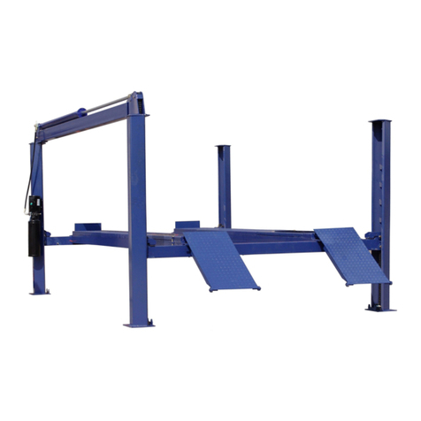
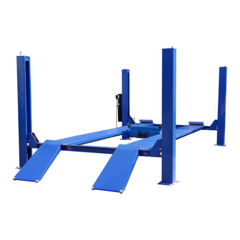
No obstructions! The open front design on our alignment lift allows
total access to front wheel adjustment points and with the cylinder located
under the track, there’s no power beam, eliminating risk of damage
to doors and mirrors. (Shown with optional rolling jack and turntables.)
14,000 LB.
FOUR POST OPEN FRONT
ALIGNMENT LIFT
FP14KO-A
14,000 lb. capacity
Four post
Open front
Alignment lift
Features:
✦14,000 lb. lifting capacity
✦Cable drive
✦Single point pneumatic safety
release mechanism
✦20” wide non-skid,
diamond plate runways
✦Powder-coated paint finish
✦C-channel construction
✦Hydraulic operation
for minimum maintenance
✦Three turntable positions for
a wide range of vehicles
✦Rear slip plates mounted on
ring roller bearings
✦Fully adjustable lock stops
for easy leveling
SPECIFICATIONS:FP14KO-A
Lifting capacity 14,000 lbs.
Overall length w/ramps 24’ 3”
Overall width 11’ 6”
Width between posts 116”
Column height 7’ 8”
Lifting height 73”
Maximum wheel base (2 wheel) 208”
Maximum wheel base (4 wheel) 158”
Runway width 20”
Width between runways 43”
Power pack 2hp 220/230 vac 20 amps

FP14KO-A
14,000 lb Capacity
Open Front Alignment Lift
ASSEMBLY & OPERATION
MANUAL


No obstructions! The open front design on our alignment lift allows
total access to front wheel adjustment points and with the cylinder located
under the track, there’s no power beam, eliminating risk of damage
to doors and mirrors. (Shown with optional rolling jack and turntables.)
14,000 LB.
FOUR POST OPEN FRONT
ALIGNMENT LIFT
FP14KO-A
14,000 lb. capacity
Four post
Open front
Alignment lift
Features:
✦14,000 lb. lifting capacity
✦Cable drive
✦Single point pneumatic safety
release mechanism
✦20” wide non-skid,
diamond plate runways
✦Powder-coated paint finish
✦C-channel construction
✦Hydraulic Operation
for minimum maintenance
✦Three turntable positions for
a wide range of vehicles
✦Rear slip plates mounted on
ring roller bearings
✦Fully adjustable lock stops
for easy leveling
SPECIFICATIONS:FP14KO-A
Lifting capacity 14,000 lbs.
Overall length w/ramps 24’ 3”
Overall width 11’ 6”
Width between posts 116”
Column height 7’ 8”
Lifting height 73”
Maximum wheel base (2 wheel) 208”
Maximum wheel base (4 wheel) 158”
Runway width 20”
Width between runways 43”
Power pack 2hp 220/230 vac 20 amps

1905 N Main St Suite C, Cleburne, TX 76033
Ph 817-558-9337 Fax 817-558-9740
TUXEDO DISTRIBUTORS LIMITED WARRANTY
Structural Warranty:
The following parts and structural components carry a five year warranty:
Columns Top Rail Beam Uprights Arms Swivel Pins
Legs Carriages Tracks Overhead BeamCross Rails
Limited One-Year Warranty:
Tuxedo Distributors, LLC (“Tuxedo”) offers a limited one-year warranty to the original purchaser of
Tuxedo lifts and Wheel Service in the United States and Canada. Tuxedo will replace, without charge, any
part found defective in materials or workmanship under normal use, for a period of one year after purchase.
The purchaser is responsible for all shipping charges. This warranty does not apply to equipment that has
been improperly installed or altered or that has not been operated or maintained according to specifications.
Other Limitations:
This warranty does not cover:
1. Parts needed for normal maintenance
2. Wear parts, including but not limited to cables, slider blocks, chains, rubber pads and pulleys
3. Replacement of lift and tire changer cylinders after the first 30 days. A seal kit and installation
instructions will be sent for repairs thereafter.
4. On-site labor
Upon receipt, the customer must visually inspect the equipment for any potential freight damage before
signing clear on the shipping receipt. Freight damage is not considered a warranty issue and therefore must
be noted for any potential recovery with the shipping company.
The customer is required to notify Tuxedo of any missing parts within 72 hours. Timely notification must
be received to be covered under warranty.
Tuxedo will replace any defective part under warranty at no charge as soon as such parts become available
from the manufacturer. No guarantee is given as to the immediate availability of replacement parts.
Tuxedo reserves the right to make improvements and/or design changes to its lifts without any obligation
to previously sold, assembled or fabricated equipment.
There is no other express warranty on the Tuxedo lifts and this warranty is exclusive of and in lieu of all
other warranties, expressed or implied, including all warranties of merchantability and fitness for a
particular purpose.
To the fullest extent allowed by law, Tuxedo shall not be liable for loss of use, cost of cover, lost profits,
inconvenience, lost time, commercial loss or other incidental or consequential damages.
This Limited Warranty is granted to the original purchaser only and is not transferable or
assignable.
Some states do not allow exclusion or limitation of consequential damages or how long an
implied warranty lasts, so the above limitations and exclusions may not apply. This warranty
gives you specific legal rights and you may have other rights, which may vary from state to state.

INTRODUCTION
Model FP14KO-A is a four-post lift is used in wheel alignment, vehicle inspection and maintenance for
various types of cars and light trucks.
Features:
- Open front end for easy access car servicing
- Multi-position cut-out for turntables (optional part) and extra long rear slip plates to accommodate a
wide range of vehicles.
- Over load safety release valve in pump and hydraulic system.
- Pneumatic lock release system and redundant cable failure safety device.
- Built in rails for rolling jacks.
2
SPECIFICATIONS
CAPACITY: 14000LBS/6300Kg
MOTOR POWER: 220V, single phase, 2.2 Kw, 10 A
HYDRAULIC PUMP OIL: 10-WT hydraulic oil or DEXRON-III ATF fluid.
WORKING TEMPERATURE: 5 – 40 ℃
NOISE: ≤76 db
OVERALL LENGTH: 294” (7403mm) OVERALL WIDTH: 139” (3530mm)
PLATFORMLENGTH: 2431/4”(6178mm) PLATFORMWIDTH: 19”(510mm)
MAX PLATFORM HEIGHT: 72 7/8”(1850mm) MIN PLATFORM HEIGHT: 8 1/4”(211mm)
LIFTING TIME (AVERAGE): 50 sec LOWERING TIME (MAX): 60 sec

3
Note: All d
Fig. 1
imensions typical

4
TOOLS REQUIRED IN INSTALLATION
Rotary hammer drill or similar
3/4” Masonry bit
Hammer
4 foot level
Open-end wrench set : 7/16” – 1-1/8”
Socket and ratchet set: 7/16” – 1-1/8”
Hex-key / Allen wrench set
Medium crescent wrench
Medium pipe wrench
Crow bar
Chalk line
Medium flat screwdriver
Tape measure: 25 foot minimum
Needle nose pliers
Fork lift

INSTALLATION
IMPORTANT NOTICE
These instructions must be followed to insure proper installation and operation of your lift.
Failure to comply with these instructions can result in serious bodily harm and void product
warranty. Manufacturer will assume no liability for loss or damage of any kind, expressed or
implied resulting from improper installation or use of this product.
PLEASE READ ENTIRE INSTRUCTION BEFORE STARTING TO ASSEMBLE THE LIFT
STEP 1: (Selecting Site) Before installing your new lift, check the following:
1. LIFT LOCATION: Always use architects plans when available. Check layout dimension against floor
plan requirements making sure that adequate space is available (See FIG. 2). The specified safety
distances must be from front wall 63 inch (1600mm) , from side wall 39 1/2 inch (1000
mm) at least. The room ceiling must be at least 157 1/2 inch (4000mm) in height.
Fig. 2
T
O
t
2. FLOOR REQUIREMENTS: The lift should be installed on a 3000 PSI concrete with little gradients.
hickness of concrete ≥6 inch (150 mm). The leveling of whole area ≤3/8 inch (10 mm).
r, every column shall be located on a concrete block with size at least 24*24 inch (600*600 mm),
hickness ≥8 inch (200mm)
STEP 2: (Unloading and Unpacking)
1. After unloading the lift, place it near the intended installation location.
2. Remove the shipping bands and packing materials from the unit.
3. Remove the packing brackets and bolts holding the two columns together. (Do not discard
bolts, they may be used in the assembly of the lift )
STEP 3: (Site Layout)
1. Once a location is determined, use a carpenters chalk line to layout a grid for the platform
locations. (See Fig.1). Keep all dimensions square and within 1/8”otherwise a malfunction of
the lift will occur.
5
2. Before continuing with the installation it is helpful to get a visual look of the shop, and other
clearances. Also, this is a good time to drive a vehicle into the position and check for
adequate clearance.

3. Note: All 4 legs should be level and square. Use the layout dimensions for floor layout
purposes only
NOTE
All models MUST be installed on 3000PSI concrete only confirming to the minimum
requirements. New concrete must be adequately cured by at least 28 days minimum.
STEP 4: (Locate the parts)
1. Use fork lift to move the platforms in the desired position. Use a wooden block or safety stand under
the platforms to set them about 12” (300mm) off the ground and parallel to each other.
2. Put the cross beams and columns near their positions.
STEP 5: (rear crossbeam )
1. Take off the cable sheave by unlocking the screws and pins on both ends of the cross beam
2. Attach the rear crossbeam to the left ( main) platform with cylinder and cables.
3. Line the cables through the hole on the crossbeam out from the end. Be sure the cables are
in the proper sheave grooves. (Fig .3 & parts drawing-2)
9495
96
93
Fig. 3
4. Take off the two cable sheaves also on the ends of sub platform. Line the longest cable
through the sub platform.
5. Connect the cross beam with the platforms by bolts.
6. Put back all the cable sheaves on cross beam and sub platform.
7. Move the rear columns to the cross beam. Unlock the nuts on the top of the column to pull up
the safety rack above the cross beam then insert it through the cross beam end. Make sure
the safety lock can rest on the rack. ( Fig 4)
6
8. Line the cable up to the top of the column. Make sure the slack cable lock is pushed by the
cable. Tighten up the nut on the cable end and rack end.( Fig. 5)

9. Mount on the plastic slide blocks on the crossbeam.( Fig. 6)
10. Fix the lower end of the safety rack by a bolt. (Fig 7)
7
Fig4 Fig.5 Fig.6 Fig.7
STEP 6: (front yoke )
1. Lay down the front columns. Take out the safety rack.
2. Take off the cable sheaves of the front yokes.
3. Slide the front yoke into its column ( open hole towards the platform)
4. Insert the safety rack through the yoke same as the rear cross beam.
5. Set up the front columns. Move them to the front end of the platforms.
6. Raise up the front yoke to touch the platform then rest on the safety rack. ( At least one man
to take care of the column. It is unstable at this step)
7. Line the cable through the yoke and column.
8. Bolt the yoke with the platform.
9. Fix the bolt on the lower end of the safety rack.
10. Do the same with another front yoke.
STEP 7: (anchor the front columns )
1. Check carefully with the location of the columns and its plumb. Using a tape measure to
measure the distance between the opposite corners of the base plate on the columns. Equal
values will insure the lifting arms will be in square.
2. Using the base plate on the front column as a guide, drill an anchor hole on the back of the
column in the concrete approximately 51/2” deep using a rotary hammer drill and 3/4” concrete
drill-bit. To assure full holding power, do not ream the hole or allow the drill to wobble.
3. Anchor the front column for safety.
STEP 8: (hydraulic system )
1. Mount on the motor pump on the column with bracket. (Fig. 8)
2. Also mount the air-release valve bracket with the pump ( Fig. 9)
3. Connect the hose from pump to cylinder with the connector supplied.
4. Fill the tank with hydraulic oil ( about 10 liters)
5. Have a certified electrician to run the 220V/60Hz single phase power supply to the motor. Be
sure to size the wire for a 25 amp circuit.
6. Mount on the air-release valve. Connect the compressed air supply through pipe supplied.

8
Fig.8 Fig.9
STEP 9: (check again )
1. Raise the platform a little by pushing the up button on the power unit.
2. Check the location of all the columns again. Make sure everything is OK.
3. Again using the base plate of the column as guide, drill all the holes for anchoring.
4. Anchor all the columns using bolts supplied. Make plumb by placing shims as close as
possible to the anchor bolts. This will prevent bending the column base plates.
5. Check that all the cables are in sheave grooves.
6. Check the leveling of the platforms. Adjust the length of the cables by the nuts on cables end
to level the platforms.
7. Lower the platforms by simultaneously pressing the air-release valve and the release lever
on the power unit.
8. If the platforms not level, adjust the height of the safety rack by the nut on the top of the
column. Do not forget to tighten the bolt on the lower end of the rack.
9. Put on all the accessories such as front stop, ramp, cover etc.
STEP 10: (start up)
1. Do not place any vehicle on the lift at this time!
2. Cycle the lift up and down several times to insure lock latches click together and all air is
removed from the system.
3. To lower the lift, the air- releases valve must be manually pressed while the lowering handle
of the pump is pressed. Latches will automatically reset once the lift ascends approximately
17”"from base.

9
.
.
.
P
t
W
t
OPERATION
RAISE-LIFT
1. Press button on power unit
The latch mechanism will ‘trip over’ when the lift raises and drop into each latch stop. But, to lock
the lift you must press the lowering handle to relieve the hydraulic pressure and let the latch set
tight in a lock position.
Always lock the lift before going under the vehicle. Never allow anyone to go under the lift when
raising or lowering. Read the safety procedures in the manual.
LOWER LIFT
1. Raise the lift until the latch clears.Approx. 2”
2. Push air valve for latch release while pressing the lowering handle on the power unit.
Note: It is normal for an empty lift to lower slowly-it may be necessary to add weight.
SAFETY PROCEDURES
zNever allow unauthorized persons to operate lift. Thoroughly train new employees in the
operation and care of lift.
zCaution: the power unit operates at high pressure
zNever permit passengers to ride in the vehicle
zProhibit unauthorized persons from being in shop area while lift is in use
zNever exceed total lift capacity of 14000-lbs.
zrior to lifting vehicle, walk around the lift and check for any objects that might interfere with
he operation of lift and safety latches; tools, air hoses, shop equipment.
zhen approaching the lift with a vehicle, center the vehicle wheel on the runway. Slowly drive
he vehicle up on the runways. Have some one outside the vehicle guide the driver.
zNever use lift to raise one end or one side of vehicle.
zPrior to lowering vehicle, walk around the lift and check for any objects that might interfere
with the operation of lift and safety latches; tools, air hoses, shop equipment. Slowly drive the
vehicle out. Have some one outside the vehicle guide the driver.
ALWAYS LOCK THE LIFT BEFORE GOING UNDER THE VEHICLE. NEVER
ALLOW ANYONE TO GO UNDER THE LIFT WHEN RAISING OR LOWERING.

10
MAINTENANCE SCHEDULE
The following periodic maintenance is the suggested minimum requirements and minimum
intervals; accumulated hours or monthly period, which ever comes sooner. If you hear a noise or
see any indication of impending failure - cease operation immediately – inspect, correct and / or
replace parts as required.
WARNING: OSHAREQUIRES USERS TO INSPECT LIFTING EQUIPMENTAT THE
START OF EVERY SHIFT. THESE AND OTHER PERIODIC INSPECTIONS ARE
THE RESPONSIBILITY OF THE USER.
DAILY PRE-OPERATION CHECK (8 HOURS)
The user should perform daily check. ATTENTION! LOOK OUT! Daily check of safety latch
system is very important-the discovery of device failure before needed could save you from
expensive property damage, lost production time, serious personal injury and even death.
zCheck safety lock audibly and visually while in operation
zCheck safety latches for free movement and full engagement with rack.
z
z
z
z
z
z
z
z
Check hydraulic connections, and hoses for leakage.
Check cables connections- bends, cracks-and looseness
Check for frayed cables in both raised and lowered position.
Check snap rings at all rollers and sheaves.
Check bolts, nut, and screws and tighten.
Check wiring & switches for damage.
Keep bass plate free of dirt, grease or any other corrosive substances.
Check floor for stress cracks near anchor bolts.
WEEKLY MAINTENANCE (40 HOURS)
zCheck anchor bolts torque to 150 ft/Ibs. for the ¾” anchor bolts. Do not use impact
wrench.
z
z
z
z
o
z
z
z
z
hy
Check floor for stress cracks near anchor bolts
Check hydraulic oil level.
Check and tighten bolts and nuts, and screws.
Check cylinder pulley assembly for free movement or excessive ware on cylinder yoke
r pulley pin.
Check cable pulley for free movement and excessive ware.
YEARLY MAINTENANCE
Lubricate cable sheaves.
Grease rub blocks and column surface contacting rub blocks
Change the hydraulic fluid- good maintenance procedure makes it mandatory to keep
draulic fluid clean. No hard fast rules can be established;-operating temperature, type of

11
se
corvice, contamination levels, filtration, and chemical composition of fluid should be
nsidered. If operating in dusty environment shorter interval may be required.
The following items should only be performed by a trained maintenance expert.
z
z
z
z
z
z
z
Replace hydraulic hoses
Replace cables and rollers.
Replace cables and sheaves.
Replace or rebuild air and hydraulic cylinders as required.
Replace or rebuild pumps / motors as required.
Check hydraulic and air cylinder rod and rod end (threads) for deformation or damage.
Check cylinder mount for looseness and damage.
Relocating or changing components may cause problems. Each component in the system must
be compatible; an undersized or restricted line will cause a drop in pressure. All valve, pump, and
hose connections should be sealed and/ or capped until just prior to use air hoses can be used to
clean fittings and other components. However, the air supply must be filtered and dry to prevent
contamination. most important- cleanliness- contamination is the most frequent cause of
malfunction or hydraulic equipment.

PARTS DRAWING-1
1
7
9
10
4
3
56
1112 6
12
612
17 1819
16
20
2425
212223
26
23
8
13
14
15
12

PARTS DRAWING-2
III
38 2234
12 6
16
52
93
94
95
96
97
97
102
103
13

PARTS DRAWING-3
53
4041
54
55
70
71
72 73
3
74
33 75
33
43
33 22
76
PART1-A
PART2-A
PART2-B
PART1-B
14

PARTS DRAWING-4
PART2-B
PART1-B
92
79
80 81
82
73
72
PART1-A
PART2-A
40 83 84
70 54 43 33
85 86 87 8880 81
80
89
33
22
90
33
91
15

PARTS DRAWING-5
27
4
3
28
29
30
31
32
33 22
34 22353637
38 2234
39
4041
42
3343
44
40 41
45
4333
45
46
47
48
49
50
51
52
16
Table of contents
Other Tuxedo Lifting System manuals

Tuxedo
Tuxedo M-1000C Owner's manual

Tuxedo
Tuxedo M-1500C-HR Instruction manual

Tuxedo
Tuxedo PL6K User manual

Tuxedo
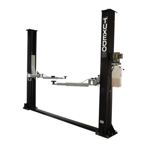
Tuxedo FP14K User manual
Tuxedo
Tuxedo M-1500C-HR User manual

Tuxedo
Tuxedo MR6K-38 User manual
Tuxedo
Tuxedo LR-26-PAD Parts list manual

Tuxedo
Tuxedo JMC9KAC-TUX User manual
Tuxedo
Tuxedo TP11KC-DX User manual
Tuxedo
Tuxedo TP9KACX User manual
Popular Lifting System manuals by other brands

Bend-Pak
Bend-Pak XP-10CX Installation and operation manual

ARJO HUNTLEIGH
ARJO HUNTLEIGH maxi sky 440 Instructions for use

WorkPro
WorkPro LW 461R Using & installation user manual

Bend-Pak
Bend-Pak XPR-9S Service manual

KEBCO
KEBCO COMBIVERT F4-F quick reference

WorkPro
WorkPro LW 415R PRO Installation & user manual