Package
Overview
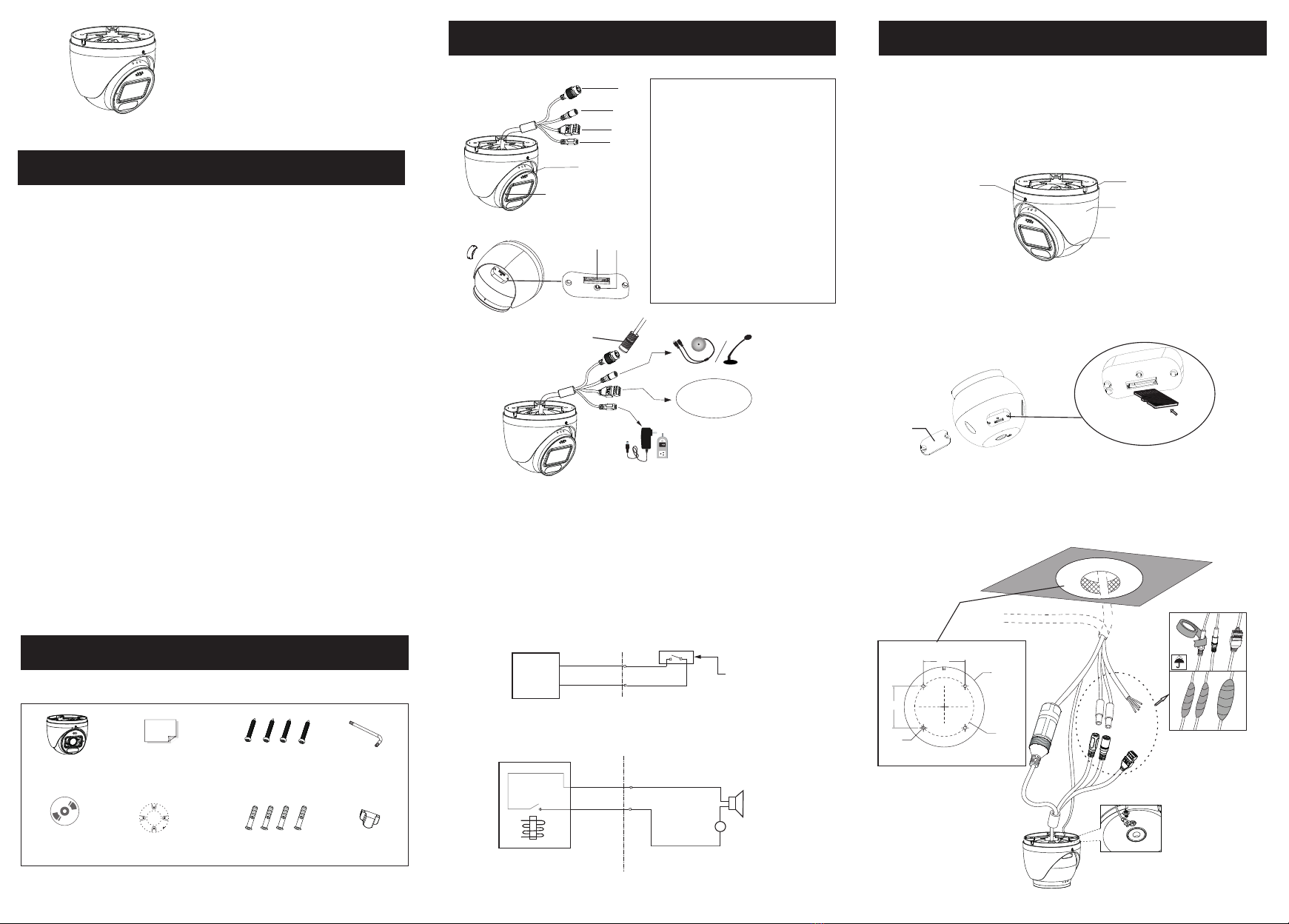
1
2
3
Warning and Caution
■ If the product does not work properly, please contact your dealer or the
nearest service center. Never attempt to disassemble the camera yourself.
(We shall not be responsible for any problems caused by unauthorized
repair or maintenance.)
■ Do not allow water or liquid intrusion into the camera.
■ In the use of the product, you must be strict compliance with the electrical
safety regulations of the nation and region. When the product is mounted on
wall or ceiling, the device shall be firmly fixed.
■ Do not use camera beyond specified voltage range.
■ Do not drop the camera or subject it to physical shock.
■ Avoid touching the camera lens.
■ If cleaning is necessary, please use clean cloth to wipe it gently.
■ Do not aim the camera at the sun or extra bright place.
■ Do not place the camera in extremely hot, cold (the operating temperature
shall be -30˚C~60˚C), dusty or damp locations, and do not expose it to high
electromagnetic radiation.
■ To avoid heat accumulation, good ventilation is required for operating
environment.
■ Please read this instruction carefully before operating the unit and keep
it for further reference.
■ All the examples and pictures used here are for reference only.
■ The contents of this manual are subject to change without notice.
Quick Start Guide
Network Camera
Camera Quick start guide
CD Plastic plug × 4 Rubber plugDrill template
Screwdriver
Tapping screw ×4
1
2
3
4
5
6
7
8
Ethernet connector
Audio input connector
Alarm input/output
Power connector
Speaker
Microphone
Micro SD card slot
Reset
► Connecting Alarm Input/Output
Alarm Input
Installation
4
Please make sure that the wall or ceiling is strong enough to
withstand 3 times the weight of the camera. Please install and use
the camera in the dry environment.
① Loosen the fixed screw to disassemble the camera.
Fixed Screw Mounting Base
Enclosure
Dome
② Unscrew the cover of the dome and then insert a micro SD card.
After that, install back the cover and make sure the cover is installed
firmly.
Insert a micro SD c ard
Cover
③ Drill the screw holes and the cable hole on the ceiling according
to the drill template. Then route and connect the cables.
Earth wire connection
8
1
2
3
4
5
6
7
1--ALARM-COM
2--ALARM_OPEN
3--ALARM_INA
4--ALARM_GND
DC12V
Ø107.7
Ø5.0 Ø79.4
56.1
56.1
(mm)
* 1
* 2 This series can be powered by DC 12V/PoE power supply. If the PoE switch is used to power
the camera, DC12V power supply is not required.
It is recommended to install the security cap for outdoor installation.
* 3 Press and hold the reset button for more than 10 seconds to restore to the factory default setting.
Security cap
ALARM-INA
ALARM-GND
Alarm input device
Max. Load: 30VDC, 1A
IPC
Relay
ALARM-COM
ALARM-OPEN
-
+
DC
Alarm output
IPC
Alarm output
device
(eg. Switch or sensor)


