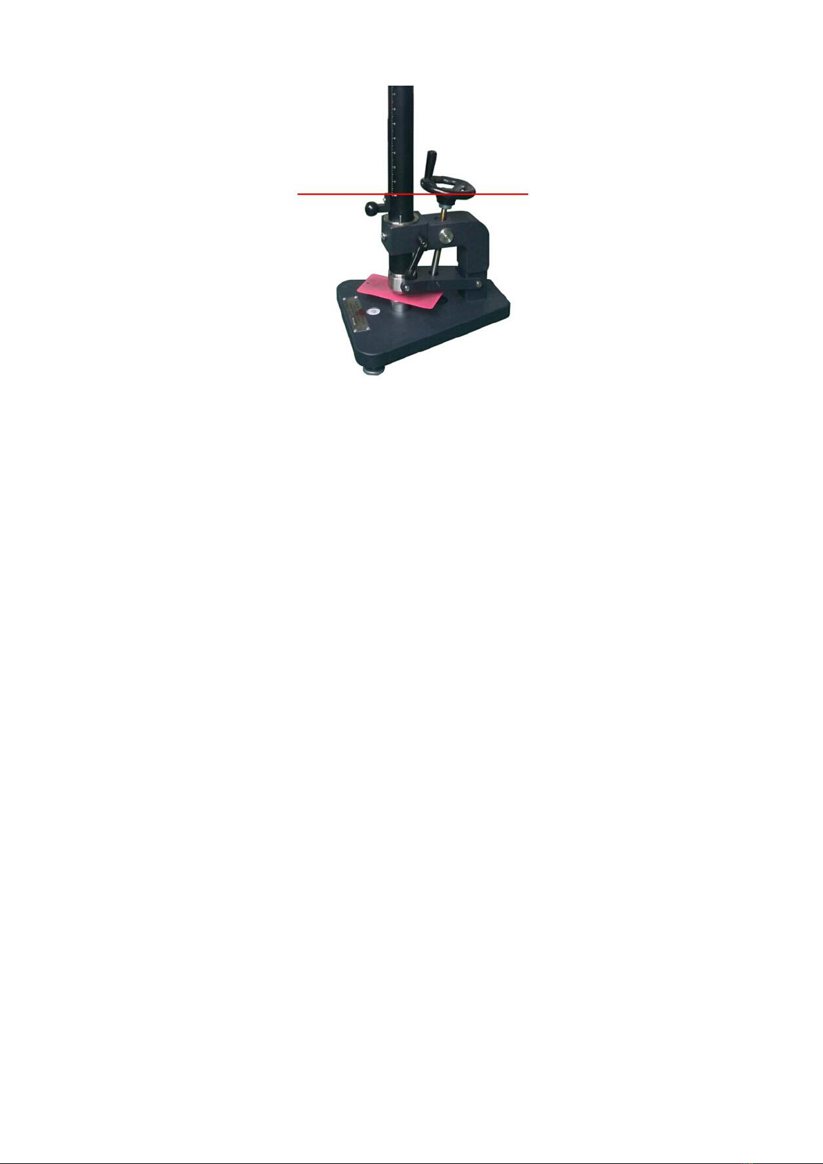
position by means of the clamping sleeve.
4.3.3.4 Lift the weight to the height limit ring, and let it fall on to the test panel.
4.3.3.5 Remove the test panel from the apparatus and examine the deformed area with the lens for coating
cracks and/or peeling from the substrate. If no cracks and/or peeling are evident, repeat the procedure at
successively greater heights until cracks and/or peeling are observed, the increments in the height being 25
mm or multiples of 25 mm. Note the height where cracks and/or peeling are observed for the first time.
If no cracks and/or peeling are observed when the weight is dropped from the maximum height allowed by
the apparatus, repeat the operation (starting at the lowest height setting)with an additional weight, making
a total of 2 kg.
If no cracks and/or peeling are observed, repeat the operation (starting at the lowest height setting)with
a further additional weight, making a total of 3 kg. Where required, a final additional weight may be added to
give a maximum mass of 4 kg.
4.3.3.6 Once cracks and/or peeling are observed, carry out the following procedure. Release the appropriate
weight and allow it to fall on to a test panel five times at different positions from each of the following heights:
◆the height where cracks and/or peeling were first observed during the procedure described in 4.3.3.5;
◆25 mm below this height;
◆25 mm above this height.
Test in a random fashion, taking care that not all impacts from one height are made in succession on one
panel.
4.3.3.7 Examine, using the lighting and the procedure specified in ISO 13076, the relevant areas of the
coating with the10 times magnifier for cracking and/or peeling from the substrate and tabulate all results as
pass or fail. Report as the end point of the test the mass/height combination for which the results change from
mainly passing to mainly failing.
4.3.3.8 If no end point can be established, repeat the procedure in 4.3.3.6 and 4.3.3.7, taking all heights 25
mm higher or lower, as appropriate, to ensure that the end point of the test is covered by the range of heights
tested.
Note:
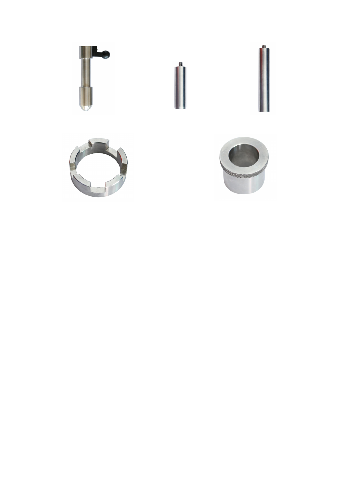
1. About the usage of the stops:
Stops apply to ISO 6272-1, use with 20mm steel indenter. The depressed depth is 10mm impacted by 20mm indenter
without stops(no test panel). If it requires 7mm in depressed depth, then it needs 1mm and 2mm 2 piece of stops, and
the like. Actually, different materials and thickness will cause the depressed depth different, so it needs to repeatedly
combine those stops until it reaches the required depressed depth.
The depressed depth of this apparatus should be 2mm at least, that is, the amount of stops can be 8mm at most; do
not install all the stops at the same time in case damage the apparatus.
2. If it needs replace different weights, please loosen the screw and lock handle, and take out the tube, then re-install the
apparatus according to 4.2.2~4.2.8
5.0 Notice
5.1 If the deepest depressed point deviates from the center of impact area, please contact with the
manufacture to calibrate.
5.2 If it needs to exchange a different weight and indenter, please loosen the screw for tube and the lock
handle, dismantle the tube and re-install the apparatus according to 4.2.2~4.2.8.
5.3 Regularly check the surface of the hemispheroid, exchange it in time if it gets deformed, rust, broken or
other failures.
5.4 Dismantle all the weights, indenter, and panel support, then clean them put them back to the package after