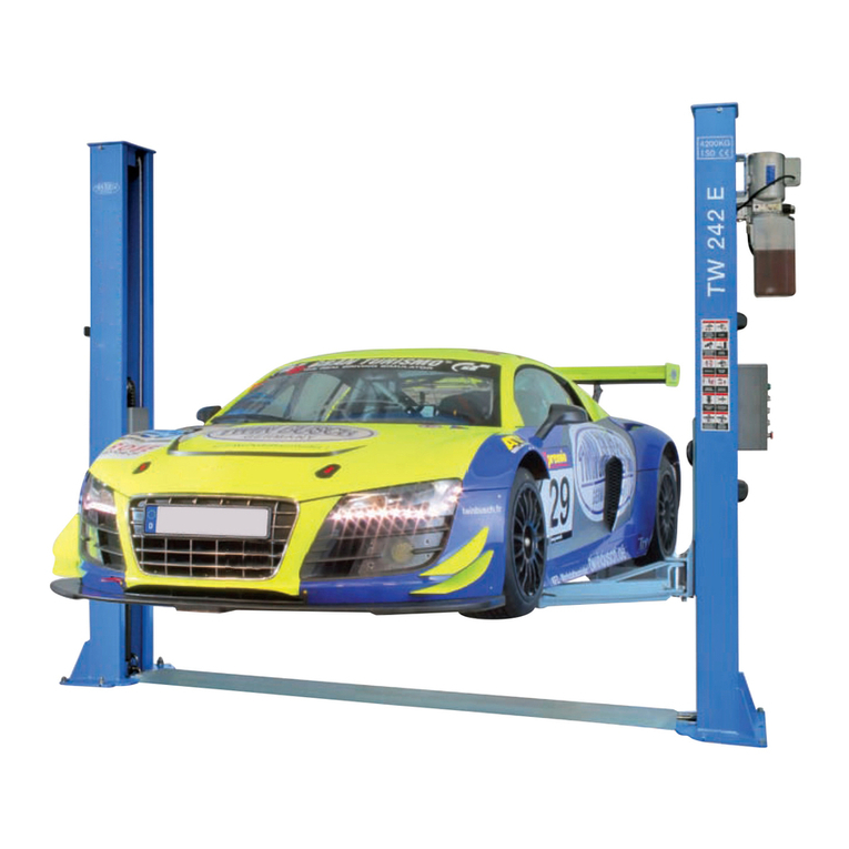
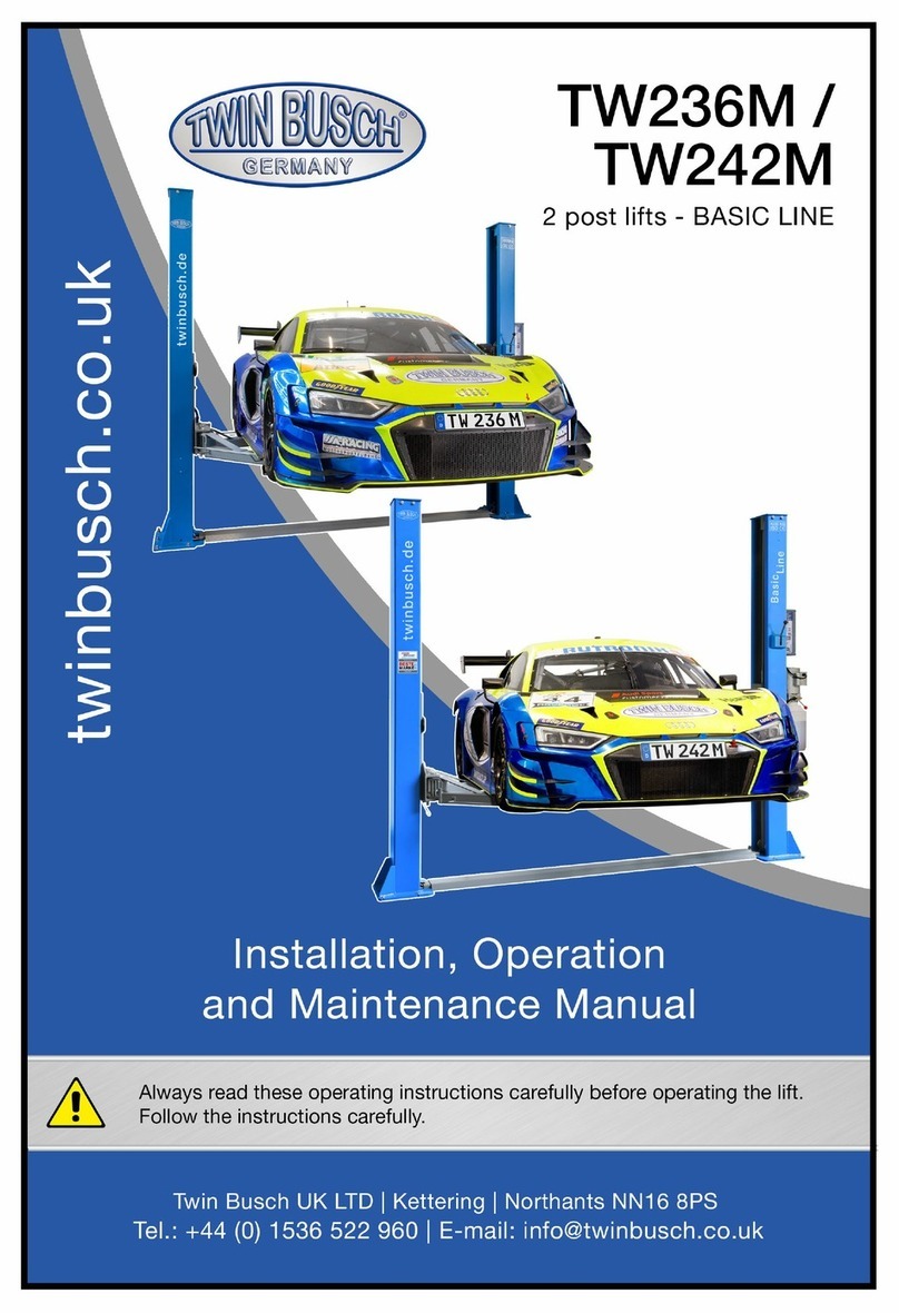
twin busch Basic-Line TW 242 GE User manual

Manual of 2-post lift garage model TW242GE
TW242GE_2-post_lift_garage_model_manual_uk_00_20231206.pdf
Version: -00, 06.11.2023

Manual of 2-post lift garage model TW242GE
TW242GE_2-post_lift_garage_model_manual_uk_00_20231206.pdf
Version: -00, 06.11.2023
Table of contents
1. General information ............................................................................................................................1
2. Identification of the instructions for use ...............................................................................................1
3. Technical data......................................................................................................................................1
4. Modification of the product .................................................................................................................1
5. Important notes / warnings..................................................................................................................2
5.1 Important note............................................................................................................................................2
5.2 Specialised personnel ..................................................................................................................................2
5.3 Safety instructions.......................................................................................................................................2
5.4 Safety devices..............................................................................................................................................3
5.5 Monitoring and testing the safety equipment.............................................................................................3
5.6 Warnings and symbols ................................................................................................................................4
5.7 Load distribution .........................................................................................................................................5
6. Compliance with the product ...............................................................................................................5
7. Technical specification .........................................................................................................................5
7.1General technical description......................................................................................................................5
7.2 Machine description....................................................................................................................................6
8. Installation ..........................................................................................................................................7
8.1 Before installation .......................................................................................................................................7
8.2 Precautions before installation....................................................................................................................7
8.3 Structure......................................................................................................................................................8
8.4 Checkpoints after installation....................................................................................................................15
9. Operating instructions .......................................................................................................................16
9.1 Safety precautions.....................................................................................................................................16
9.2 Flow chart .................................................................................................................................................16
9.3 Operating instructions (lifting and lowering process)................................................................................17
9.4 Description of the switch box (control box) ...............................................................................................17
10. Operating instructions .......................................................................................................................18
11. Maintenance .....................................................................................................................................19
11.1 Daily inspection of parts before operation ................................................................................................19
11.2 Weekly inspection of the parts ..................................................................................................................19
11.3 Monthly inspection of parts ......................................................................................................................19
11.4 Annual inspection of the parts ..................................................................................................................20
12. Behaviour in the event of an incident .................................................................................................20
13. Appendix ...........................................................................................................................................21

Manual of 2-post lift garage model TW242GE
TW242GE_2-post_lift_garage_model_manual_uk_00_20231206.pdf
Version: -00, 06.11.2023
13.1 Packing list for the lift................................................................................................................................21
13.2 General diagram .......................................................................................................................................22
13.3 Diagram for floor fastening / foundation plan ..........................................................................................23
13.4 Hydraulic system .......................................................................................................................................26
13.5 Circuit diagrams ........................................................................................................................................27
13.6 Exploded views ..........................................................................................................................................32
13.7 Spare parts list ..........................................................................................................................................38
Further attachment:
⋅EU Declaration of Conformity

Manual of 2-post lift garage model TW242GE
Misprints, errors and changes excepted. Page | 1
1. General information
Garage model - Only recommended for standard garages with width restrictions and low ceiling heights! The
TW242GE Basic-Line lift was specially developed for limited space conditions. With an overall width of less than 3
m and a column height of just 2.32 m, it is the ideal solution for standard garages. The automatic safety locking
and unlocking function not only ensures effortless operation, but also additional safety when using the lift.
2. Identification of the instructions for use
Operating instructions TW 242 GE
of the Twin Busch GmbH
Ampérestraße 1
D-64625 Bensheim
Phone: +49 6251-70585-0
Telefax: +49 6251-70585-29
Internet: www.twinbusch.de
Email: info@twinbusch.de
Status: -00, 12.06.2023
File: TW242GE_2-post_lift_garage_model_manual_uk_00_20231206.pdf
3. Technical data
Power supply
230 V / 50 Hz
Protection
C 16A (slow)
Load capacity
4,200 kg
Degree of protection
IP 54
Lifting time
approx. 45 sec
Lowering time
approx. 30 sec
Net weight
540 kg
Noise level
< 70 db
Working environment
Working temperature: -15°C to +40°C
rel. Humidity: 30% to 85%
4. Modification of the product
Improper use, modifications, conversions and attachments of the lift and all its components that have not been
agreed with the manufacturer are not permitted. The manufacturer accepts no liability for improper installation,
operation or overloading. Improper use also invalidates the CE certification and the validity of the certificate.
If you require any changes, please contact your dealer or the expert staff at Twin Busch GmbH beforehand.
Twin Busch UK Ltd.
9, Linnell Way
Telford Way Industrial Estate
NN16 8PS, Kettering (Northants)
Phone: +44 (0) 1536 522 960
Internet: www.twinbusch.co.uk
Email: info@twinbusch.co.uk

Manual of 2-post lift garage model TW242GE
Misprints, errors and changes excepted. Page | 2
5. Important notes / warnings
5.1 Important note
Neither the manufacturer nor the seller will accept liability for improper installation, improper operation,
overloading or unsuitable ground conditions.
This model is specially designed for lifting cars that do not exceed the maximum authorised weight. If you use
the lift for other purposes, neither the manufacturer nor the seller will be liable for accidents or damage.
Pay particular attention to the maximum authorised weight. A sign with the maximum authorised weight is
attached to the lift.
Never attempt to lift
vehicles that exceed the authorised maximum weight with the lift.
Read the operating instructions carefully before operating the lift to avoid personal injury.
5.2 Specialised personnel
⋅Only trained specialist personnel may operate the lift. Read and understand the safety instructions before
operating the lift.
⋅Electrical connections must be made by an electrician.
⋅Bystanders are not permitted in the vicinity of the lifting platform.
5.3 Safety instructions
⋅Do not install the lift on an asphalt surface.
⋅Read and understand the safety instructions before operating the lift.
⋅Do not leave the control unit under any circumstances when the lift is in motion.
⋅Keep hands and feet away from moving parts. When lowering, pay particular attention to
Your feet.
⋅The lifting platform may only be operated by trained personnel.
⋅Wear suitable clothing.
⋅The area around the lifting platform should always be kept free of obstructions.
⋅The lift is designed for lifting the entire vehicle, which does not exceed the maximum authorised weight.
⋅Always ensure that all safety precautions have been taken before working near or under the vehicle.
Never remove safety-relevant components from the lift. Do not use the lift if safety-relevant components
are missing or damaged.
⋅Do not under any circumstances move the vehicle or remove heavy objects from the vehicle that could
cause significant weight differences while the vehicle is on the lift.
⋅Always check the manoeuvrability of the lift to guarantee its performance.
Ensure regular maintenance. If an irregularity occurs, stop the work
with the lift immediately and contact your dealer.
⋅Lower the lift completely when it is not in use. Do not forget to disconnect the power supply.
⋅If you do not use the lift for a longer period of time:
a.) Disconnect the lift from the power source.
b.) Empty the oil tank.
c.) Lubricate the moving parts with hydraulic oil.
Caution: To protect the environment, dispose of the unused oil in an appropriate manner.

Manual of 2-post lift garage model TW242GE
Misprints, errors and changes excepted. Page | 3
5.4 Safety equipment
The lift is equipped with the following safety devices to ensure safe operation *):
⋅Safety catches
⋅Throttle valve in hydraulic line
⋅Limit switch
⋅Support arm lock
⋅Devices to prevent jamming and crushing (shaft protection, foot deflector)
⋅Synchronisation cables
*) depending on the design and type of lift
5.5 Monitoring and testing the safety equipment
⋅Safety catches: Function test, when lowering the lift, safety catches must engage and
stop the downward movement.
⋅Throttle valve: Fixed throttle, cannot be checked by the user.
⋅Limit switch: If the limit switch is pressed, the motor stops or cannot start.
⋅Support arm lock: When the support arms are raised, the support arm lock must engage
and remain securely locked in place under lateral load.
⋅Equipment clamps etc.: The equipment must be in place, functional and not deformed.
⋅Synchronisation cables: Check condition.

Manual of 2-post lift garage model TW242GE
Misprints, errors and changes excepted. Page | 4
5.6 Warnings and symbols
All warnings are clearly visible on the lift to ensure that the user uses the device in a safe and appropriate
manner.
The warning signs must be kept clean and replaced if they are damaged or missing. Please read the signs
carefully and memorise their meaning for future use.
Instructions before use
and safety instructions
read carefully!
The lift may only be
operated by qualified
personnel!
Repairs and maintenance may
only be carried out by
specialised personnel, never
put safety devices out of
operation!
Specialist staff only
permitted in the vicinity of
the lifting platform!
Escape routes
always keep clear!
It is forbidden for persons
to stand under the lift
(when lifting or lowering)!
Pay attention to the
Let go on your feet!
Crushing hazard!
It is forbidden for persons
to stand under the lift
(when lifting or lowering)!
Observe the vehicle
manufacturer's mounting
points!
After briefly lifting the
vehicle, check that it is
securely seated!
Do not exceed the specified
load capacity!
When installing or removing
heavy parts can
tip the vehicle!
Never attempt to load only
one side of the lift!
Protect the lift from
moisture!
Electrical connections
must be
be dry!
Strong shaking
Avoid damage to the vehicle
CAUTION!
Electrical voltage!

Manual of 2-post lift garage model TW242GE
Misprints, errors and changes excepted. Page | 5
5.7 Load distribution
6. Conformity with the product
The TW 242 GE 2-post lift is CE-certified and complies with the Machinery Directive 2006/42/EC and fulfils the
standards EN 1493:2022, EN 60204-1:2018 (see under: EU Declaration of Conformity, at the end of the
instructions for use).
7. Technical specification
7.1 General technical description
This lift consists of columns, a carriage, lifting arms, cylinders, a motor unit and other components. It is
driven by an electro-hydraulic system. A gear pump delivers hydraulic oil to the oil cylinders and pushes the
pistons upwards. The moving piston sets the chain in motion, which raises both the trolley and the lifting
arms. During the lifting process, the safety pawl automatically and safely engages with the safety toothed
block in the columns. This prevents slipping in the event of a hydraulic system failure.
Security structure:

Manual of 2-post lift garage model TW242GE
Misprints, errors and changes excepted. Page | 6
7.2 Machine description
Control unit
Motor unit
Column
Hydraulic cylinder
Lifting carriage
Drive-over plate
Support arm
Turntable

Manual of 2-post lift garage model TW242GE
Misprints, errors and changes excepted. Page | 7
8. Installation
8.1 Before installation
8.1.1 Tools and equipment required:
⋅Appropriate equipment
⋅Hydraulic oil HLP32
⋅Impact drill
⋅Spanner attachments and open-end spanners, a set of Allen keys,
Phillips and slotted screwdriver
⋅Hammer, pincers, 17 mm, 19 mm, 22 mm socket spanner
8.1.2 Checklist (packing list)
Unpack all parts and use Appendix 1 to check that each part is present. Do not hesitate to contact us if any
parts are missing.
8.1.3 Soil conditions and foundation
The lift should be
installed on a smooth and solid floor with a compressive strength of more than 3 kg/mm²,
a flatness of less than 5 mm and a minimum thickness of 200 mm.
In addition, a new concrete floor must rest for at least 28 days before a lifting platform can be installed.
(See Appendix 2 for further information)
8.2 Precautions before installation
8.2.1 Check that both columns are parallel to each other and vertical to the floor. Do not tilt.
8.2.2 Check all hoses and connections.
The lift may only be put into operation if there are no leaks.
8.2.3 All screws must be screwed tight.
8.2.4 Do not place any vehicle on the lifting platform during a test run.

Manual of 2-post lift garage model TW242GE
Misprints, errors and changes excepted. Page | 8
8.3 Structure
Step 1: Remove the packaging and take out the box containing the individual parts and cover plates.
Read and understand the operating instructions before proceeding.
Step 2: Firstly, place a support between the two posts or lift one of the two posts using a suitably
secure lifting device, then remove the screws from the frame. Draw the outline of the base
plate on the floor with chalk and determine the position for the post.
Caution: Please take particular care to ensure that the column cannot fall down.
The accessories could be damaged or people could be injured.
Step 3: After you have removed the first pillar, place a support under the other pillar. Then also
remove the screws from the frame.
Step 4: Set up both columns. Align the main and secondary pillars at a distance of approx. 2500 mm
(inside of the pillars).
1. After unpacking, you must decide which side you want to place the main column on.
(the power connection and the control unit must be mounted on this). Set up the main
column, place the floor cover plate on this column and determine the exact distance by
erecting the second column and placing it on the second side of the floor cover plate.
2. During the installation process, it is imperative that you ensure that none of the columns
can tip over.
3. drill the holes in the floor for each floor anchor using a suitable percussion drill. Drill
vertically. Carefully remove dirt and dust after drilling and make sure that the posts remain
on the circle previously drawn with chalk.

Manual of 2-post lift garage model TW242GE
Misprints, errors and changes excepted. Page | 9
Step 5: Attach the mechanical safety interlocks, and electromagnets, two to each column.
Step 6: Attach the base plate. Raise the two carriages by hand approx. 800 mm from the ground to lock
them with safety latches and then place the base plate between two base plates of the columns.
Security
closing plate
Positioning aid
Electromagnet
Phillips head screw
M6x10
Phillips head screw
M6x10
Safety interlock
Electro-magnet

Manual of 2-post lift garage model TW242GE
Misprints, errors and changes excepted. Page | 10
Step 7: Install the steel cables.
1. Align the carriages on both sides approx. 800 mm above the floor.
2. Ensure that the safety catches on both columns are engaged
before attempting to connect the ropes.
3. the slides must be level with the ground before proceeding.
4. Pull in the steel cables as shown in the illustration.
5. The steel cables must be set "taut" on both sides. Ensure that
the sound of the safety latches can be heard equally on the right and left when lifting.
6. The ropes must be secured (countered) and oiled.
A: Steel cable 1
B: Steel cable 2

Manual of 2-post lift garage model TW242GE
Misprints, errors and changes excepted. Page | 11
Step 8: Mount the motor unit
Step 9: Connect the oil hose as shown in the following illustration.
Anti-shock cushion
M10 nut
M10 spring washer
M10 washer
M10x35 hexagon head screw
Motor unit
Hydraulic hose connection
Hydraulic
cylinder
Hydraulic
cylinder
Hydraulic hose
connection
Hydraulic hose
connection
Oil line 1
Oil line 2

Manual of 2-post lift garage model TW242GE
Misprints, errors and changes excepted. Page | 12
Step 10: Connect the cable.
1. Mount the switch box on the main pillar
2. Connect the quick connector between the electromagnets.
Switch box
M5x10 Phillips head screw
Quick connector
Adjustable bolt

Manual of 2-post lift garage model TW242GE
Misprints, errors and changes excepted. Page | 13
3. Connect the solenoid valve cable and the motor cable
Step 11: Attach the protective devices for cables and oil hoses.
Step 12: Assemble the support arms.
Insert the support arms into the carriage, paying attention to the interlocking of the safety blocks. Tighten
the screws. Attach the support arms to the carriage and make sure that the arm lock can function.
Electromagnet
Electromagnetic cable 4
Quick connector
Electromagnetic cable 3
Electromagnetic cable 2
Control box
Electromagnetic cable 1
(runs through the slotted base plate)
Support
Support

Manual of 2-post lift garage model TW242GE
Misprints, errors and changes excepted. Page | 14
Step 13: Fitting the protective bracket.
Step 14: Filling the hydraulic oil.
The oil tank has a capacity of 10 litres. To ensure that the lift works,
you should fill the tank to 80% with hydraulic oil (when the support arms are in the lowest position).
Hydraulic oil type: HLP 32
Locking device
Pull and turn to release the lock
Turntable
M8*12 screw
Support
arm

Manual of 2-post lift garage model TW242GE
Misprints, errors and changes excepted. Page | 15
Step 15: Test run.
1. Follow the operating instructions and ensure that no vehicle is on the lift during a test run.
no vehicle may be on the lift during a test run.
2. check the condition of all connections.
Attention:
Please ensure that the support arms are swivelled in / folded inwards to prevent collision with the oil
tank.
Note: If no support arms have been fitted and/or it is very cold, the carriages will
only lower
very slowly. Under load, the lowering speed is normal.
Step 16: Fit the overrun plate and the door stop protection
Attach the drive-over plate, the chain guards, the protective covers for the electromagnet and the guards
for the door openings.
8.4 Checkpoints after installation.
S/N
Check
YES
NO
1 Are the columns vertical to the floor? (90°)
2 Are the two columns parallel to each other?
3 Is the oil hose connected correctly?
4 Is the steel cable correctly and firmly connected?
5 Are all support arms correctly and firmly fitted?
6 Are the electrical connections correct?
7 Are the joints all screwed tight?
8 Have all parts that need to be greased been greased?
Door stop
Screws and dowels
Drive-over plate

Manual of 2-post lift garage model TW242GE
Misprints, errors and changes excepted. Page | 16
Switch on the power
Press the UP button (push-button)
Motor drives the gear pump
Chain pulls the carriage up
Start
The lifting
platform lifts
Start
The lifting platform
lowers
Press the DOWN button
9. Operating instructions
9.1 Safety precautions
9.1.1 Check all connections of the oil hose.
If there are no leaks, the lifting process can be started.
9.1.2 If the safety devices fail, the lift must not be used!
9.1.3 If the vehicle's centre of gravity is not in the middle, the lift must not
be started up or shut down. Otherwise, neither we nor the dealer will accept responsibility for any
problems or damage caused.
9.1.4 Users and other employees involved should stand in a safe area during the lifting process.
9.1.5 When the carriers have reached the desired height, switch off the power to avoid incidents. avoid
incidents triggered by bystanders.
9.1.6 Ensure that the safety catches are engaged before starting work under the vehicle. No persons may
be under the vehicle during the lifting and lowering process.
9.2 Flow chart
Lifting process
Lowering process
Cylinder moves the chain
Switch on the power

Manual of 2-post lift garage model TW242GE
Misprints, errors and changes excepted. Page | 17
9.3 Operating instructions (lifting and lowering process)
Lifting process:
1 Read and understand the operating instructions before starting work.
2. Park the vehicle between the two pillars.
3 Align the lift so that the pick-up points on the vehicle are in line with the lift. Make sure that
the vehicle is positioned correctly.
4 Switch on the lift and press the UP button on the control box until the support arm mount
touches the vehicle at the point approved by the manufacturer.
5. press the button until the vehicle is raised by about 10-15 cm. Now stop the lifting process
and make sure that the vehicle is correctly and securely supported.
6 After final alignment and checking for correct fit, press the UP button again and hold it down
until the desired height is reached. Press the safety lock button on the control panel to
activate the safety lock. Now switch off the power and then carry out maintenance or repair
work underneath.
Lowering process:
1. Switch on the power.
2. Press the "DOWN button" on the control unit. The lifting arms now automatically move
upwards by about 5CM, which releases the safety lock. The lift lowers.
3. After the carriers have been moved to the lowest position, swivel the support arms out from
under the vehicle.
4. Clear all obstacles out of the way and remove the vehicle
9.4 Description of the switch box
Description of the
Function
Main switch Switch on or off
Operating light Indicates whether there is a power supply
UP button Raising the lifting platform
Button for the safety lock (Safety
Lock) Ensuring safety in the operating process
DOWN button Lowering the lifting platform
Emergency stop Switches the system off in an emergency
Table of contents
Other twin busch Lifting System manuals
Popular Lifting System manuals by other brands

morse
morse Hydra-Lift Drum Karrier 400AM-60-124 Operator's manual

Forch
Forch 4915 20 instruction manual

Vulcan-Hart
Vulcan-Hart VPT Operator's manual

Street Crane
Street Crane ZX6 Installation, operation and maintenance instructions

EZ-ACCESS
EZ-ACCESS PATHWAY Assembly manual

Festo
Festo 532954 Assembly instructions