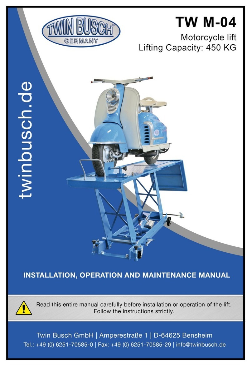
twin busch TW M-04 User manual

TWIN BUSCH GmbH
Technical changes for purposes of a technical advancement as well as deviation in colour, errors and printing mistakes are reserved.
- 1 -

TWIN BUSCH GmbH
Technical changes for purposes of a technical advancement as well as deviation in colour, errors and printing mistakes are reserved.
- 2 -

TWIN BUSCH GmbH
Technical changes for purposes of a technical advancement as well as deviation in colour, errors and printing mistakes are reserved.
- 3 -
SCISSOR LIFT INSTRUCTION MANUAL
INDEX PAGE
1. Transport and storage.................................................................................. Fehler! Textmarke nicht definiert.
1.1 Transport:..............................................................................................................................................- 4 -
1.2 Storage:.................................................................................................................................................- 4 -
2. Manual introduction........................................................................................................................................- 5 -
3. Description of the machine.............................................................................................................................- 5 -
3.1 Machine Application..............................................................................................................................- 5 -
3.2 Structure Features.................................................................................................................................- 5 -
3.4 Equipment.............................................................................................................................................- 5 -
4. Specifications.................................................................................................................................................- 6 -
4.1 Main technical parameter......................................................................................................................- 6 -
5 Operation.......................................................................................................................................................- 6 -
6 Components................................................................................................. Fehler! Textmarke nicht definiert.

TWIN BUSCH GmbH
Technical changes for purposes of a technical advancement as well as deviation in colour, errors and printing mistakes are reserved.
- 4 -
1. Manual introduction and storage
1.1 Transport:
Packing can be lifted or moved by lift trucks, cranes or bridge cranes. In case of slinging, a
second person must always take care of the load, in order to avoid dangerous oscillations.
During loading and unloading operation, goods must be handled by vehicles or ships.
At the arrival of the goods, verify that all items specified in the delivery notes are included. In case of
missing parts possible defects or damage may due to transport operations.
If finding missing parts, possible defects or damage due to transport, one should examine damaged
cartons according to <<Accessories Packing List.>> to verify the condition of damaged goods and
missing parts, also the person in charge or the carrier must be immediately informed.
The machine is heavy goods! Don’t take manpower load and unload and transporting way into
consideration, the safety of working is important.
Furthermore, during loading and unloading operation goods must be handled as shown in the
picture. (Picture 2)
Picture 2 (Goods-lifted)
1.2 Storage:
-The machine equipment should be stocked in the warehouse, if stocked outside should do the disposal
well of waterproof.
-Use box truck in the process of transport, use container storage when shipping.
-The control box should be placed perpendicularly during the transport; and prevent other goods from
extrusion.
-The temperature for machine storage : -25ºC-- 55ºC

TWIN BUSCH GmbH
Technical changes for purposes of a technical advancement as well as deviation in colour, errors and printing mistakes are reserved.
- 5 -
2. Manual introduction
This manual has been prepared for workshop personnel expert in the use of the lift operator and
technicians responsible for routine maintenance fitter.
Workers should read the <<Instruction & Maintenance Manual>> carefully before carrying out any
operation with the lift. This manual contains important information regarding:
-The personal safety of operators and maintenance workers.
-Lift safety.
-The safety of lifted vehicles.
Several tips should be done by the operator as follow:
1.Well conserving the manual. Manufacturer owns the right to make little change for the manual owing to
the improvement of technology.
2.Good disposal the used oil.
3.The machine must be demolished by authorized technicians, just like for assembling
3. Description of the machine
3.1 Machine Application
The streetwise Workshop Table Lift is designed to enable efficient and safe access allowing repairs and
servicing of most motorcycles.
The table smoothly and safety lifts the motorcycle to an optimum height and position, optimizing space in
the workshop or garage.
3.2 Structure Features
-Manual powered hydraulic mechanism
-Removable plate for increased access, such as rear wheel removal
-Fully mobile for ease of use and positioning
-Adjustable foot for increased safety and stability
-Safety bar increases safety against accidental descent of table
3.3 Equipment
-Machine basement (The position and space of equipment installation)
-Machine frame (The main structure of lift and insurance institution)

TWIN BUSCH GmbH
Technical changes for purposes of a technical advancement as well as deviation in colour, errors and printing mistakes are reserved.
- 6 -
4. Specifications
4.1 Main technical parameter
5. Operation
5.1 Setting up the TABLE LIFT
Place the table lift in the required location garage. Adjust the adjustable foot to level the table lift.
5.2 Placing motorcycle on TABLE LIFT
Ensure that the table is at the minimum height, and that the ramp is in place. Open the front wheel clamp to its
maximum setting. Two people (one on each side of motorcycle) should walk the motorcycle onto the table,
locating the front wheel into the front wheel clamp (take care not to snag any part of the wheel on the clamp).
Place the motorcycle onto its own side stand, ensuring that it is steady, then tighten the front wheel clamp to
secure the front wheel. If required, remove the RAMP. Lock off the release valve, steadily pump the foot plate
until the table reaches its maximum height. Insert the safety bar at the required height setting in the support
arms, then lower the table to the safety bar height by opening the release valve when the table is at the final
height lock off the release valve.
5.3 Removing motorcycle from TABLE LIFT
Steadily pump the foot plate until the table reaches its maximum height. Remove the safety bar from the
support arms, then open the release valve slowly and control the lowering of the table to its minimum height.
Replace the ramp onto the table, two people should then unfasten the front wheel clamp remove the
motorcycle from its stand and wheel it off the back of the table via the ramp.
Machine type
MT04
Drive
Oil cylinder
Lifting capacity
452kg
Machine lift height
780mm
Platform initial height
180mm
Table dimensions
550*2060mm
Net weight
120kg
Package size
2170*610*280mm
Table 1

TWIN BUSCH GmbH
Technical changes for purposes of a technical advancement as well as deviation in colour, errors and printing mistakes are reserved.
- 7 -
CAUTION
When not in use, always store the table lift at its lowest height position.
When the table is at its highest elevated position, do not attempt to pump the table higher as this can damage
the mechanism
When lowering the table, take care to control the speed of descent using the release lift.
Always check the table lift before use, if any signs of wear or damage are noticeable then the table lift must not
be used
No responsibility can be accepted for damage to motorcycles or injury to persons when using the table lift as
instructed.
6. Components
1. WHEEL BAR
2. FRONT WHEEL CLAMP
3. TABLE
4. REMOVEABLE PLATE
5. RAMP
6. ADJUSTABLE FOOT
7. LIFTING CYLINDER
8. RELEASE VALVE
9. FOOT PLATE
10. WHEELS
11. SAFETY BAR
12. SUPPORTARM
13. SPEEDADJUSTING SCREW

TWIN BUSCH GmbH
Technical changes for purposes of a technical advancement as well as deviation in colour, errors and printing mistakes are reserved.
- 8 -

TWIN BUSCH GmbH
Technical changes for purposes of a technical advancement as well as deviation in colour, errors and printing mistakes are reserved.
- 9 -
Other manuals for TW M-04
1
Table of contents
Other twin busch Lifting System manuals