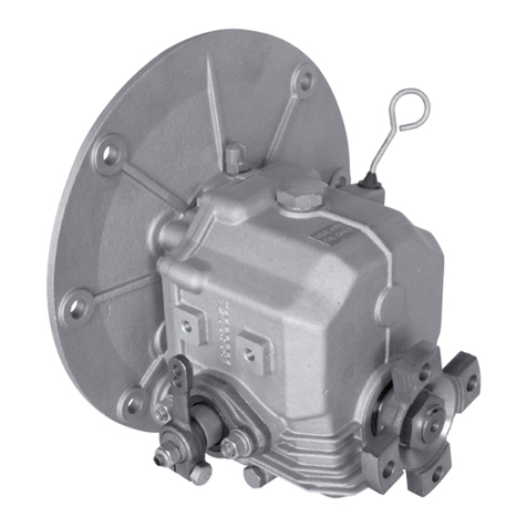
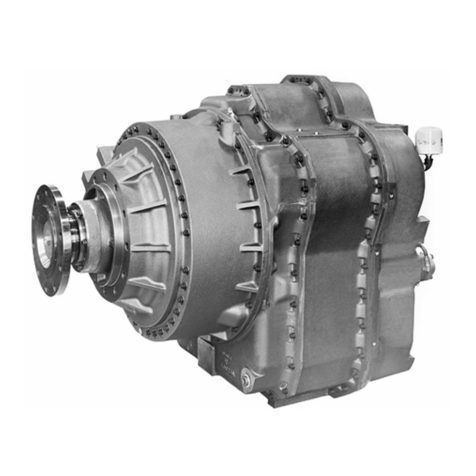
Twin Disc MG-5170DC User manual

SerSer
SerSer
Servicevice
vicevice
vice
ManualManual
ManualManual
Manual MarineMarine
MarineMarine
Marine
TT
TT
Trr
rr
ransmissionansmission
ansmissionansmission
ansmission
Document Number: 1020667
TWIN DISCTWIN DISC
TWIN DISCTWIN DISC
TWIN DISC
INCORPORAINCORPORA
INCORPORAINCORPORA
INCORPORATEDTED
TEDTED
TED
Components:
MG-5170DC

NOTICE
Twin Disc, Incorporated makes no warranty or guaranty of any
kind, expressed, implied or otherwise, with regard to the
informationcontained within this manual. TwinDisc,Incorporated
has developed this manual through research and testing of the
information contained therein. Twin Disc, Incorporated assumes
no responsibility for any errors that may appear in this manual
and shall not be liable under any circumstances for incidental,
consequential or punitive damages in connection with, or arising
out of, the use of this manual. The information contained within
this manual is subject to change without notice.

Document Number
1020667
July, 2002
Marine Transmission
Service Manual


TWIN DISC, INCORPORATED
EXCLUSIVE LIMITED WARRANTY
COMMERCIAL MARINE TRANSMISSION
A. TwinDisc,Incorporatedwarrantsallassembledproductsandparts,(exceptcomponentproductsorpartsonwhichwrittenwarranties
issued by the respective manufacturers thereof are furnished to the original customer, as to which Twin Disc, Incorporated makes no
warranty and assumes no liability) against defective materials or workmanship for a period of twenty-four (24) months from the date of
shipment by Twin Disc, Incorporated to original customer, but not to exceed twelve (12) months of service, whichever occurs first. This is the
only warranty made by Twin Disc, Incorporated and is in lieu of any and all other warranties, express or implied,
includingthewarrantiesof merchantability or fitness for a particular purpose and no other warranties are implied
or intended to be given by Twin Disc, Incorporated. The original customer does not rely upon any tests or inspections by
Twin Disc, Incorporated or on Twin Disc, Incorporated*s application engineering.
B. The exclusive remedy provided by Twin Disc, Incorporated whether arising out of warranty within the applicable
warranty period as specified, or otherwise (including tort liability), shall at the sole option of Twin Disc,
Incorporated be either the repair or replacement of any Twin Disc, Incorporated part or product found by Twin
Disc, Incorporated to be defective and the labor to perform that work and to remove and reinstall (or equivalent
credit). In this context, labor is defined as the flat rate labor hours established by Twin Disc, Incorporated in the
published Twin Disc Flat Rate Schedule, required to remove, disassemble, inspect, repair, reassemble, reinstall
and test the Twin Disc, Incorporated product only. Authorized reasonable travel and living expenses will be
considered for payment. Under no circumstances, including a failure of the exclusive remedy, shall Twin Disc,
Incorporated be liable for economic loss, consequential, incidental or punitive damages. The above warranty and
remedy are subject to the following terms and conditions:
1. Complete parts or products upon request must be returned transportation prepaid and also the claims submitted to Twin Disc,
Incorporated within sixty (60) days after completion of the in-warranty repair.
2. Thewarrantyis void if, in the opinion ofTwinDisc,Incorporated,thefailureofthepartor product resulted from abuse, neglect,
improper maintenance or accident.
3. The warranty is void if any modifications are made to any product or part without the prior written consent of Twin Disc,
Incorporated.
4. The warranty is void unless the product or part is properly transported, stored and cared for from the date of shipment to the
date placed in service.
5. The warranty is void unless the product or part is properly installed and maintained within the rated capacity of the product or
partwithinstallationsproperlyengineeredandinaccordancewiththepractices,methodsandinstructionsapprovedorprovided
by Twin Disc, Incorporated.
6. The warranty is void unless all required replacement parts or products are of Twin Disc origin or equal, and otherwise identical
with components of the original equipment. Replacement parts or products not of Twin Disc origin are not warranted by Twin
Disc, Incorporated.
C. As consideration for this warranty, the original customer and subsequent purchaser agree to indemnify and hold Twin Disc,
Incorporated harmless from and against all and any loss, liability, damages or expenses for injury to persons or property, including
without limitation, the original customer*sand subsequent purchaser*semployees and property, due to their acts or omissions or the
acts or omissions of their agents, and employees in the installation, transportation, maintenance, use and operation of said equipment.
D. Only a Twin Disc, Incorporated authorized factory representative shall have authority to assume any cost or expense in the service,
repair or replacement of any part or product within the warranty period, except when such cost or expense is authorized in advance
in writing by Twin Disc, Incorporated.
E. Twin Disc, Incorporated reserves the right to improve the product through changes in design or materials without being obligated to
incorporate such changes in products of prior manufacture. The original customer and subsequent purchasers will not use any such
changes as evidence of insufficiency or inadequacy of prior designs or materials.
F. If failure occurs within the warranty period, and constitutes a breach of warranty, repair or replacement parts will be furnished on a
no-charge basis and these parts will be covered by the remainder of the unexpired warranty which remains in effect on the complete
unit.
September 4, 2001 TDWP2003

TWIN DISC, INCORPORATED
FLAT RATE HOUR ALLOWANCE
(Hourly Labor Rate Must be Acceptable to Twin Disc, Incorporated.)
COMMERCIAL MARINE TRANSMISSIONS - ALL RATIOS:
MODEL SERIES R&R UNIT REBUILD CLUTCH REPAIR
(BOTH PACKS)
MG 502, MG 5010, MG5011, MG5005A
MG5015A 10.0 8.0 -
MG 506, MG5061, MG 5050, MG5055A 10.0 11.0 -
MG 507, MG 5081, MG5085, MG5090, 10.0 12.0 -
MG 5091 10.0 12.0 4.0
MG5112,MG5113 10.0 17.0 -
MG 509, MG 5111, MG5114 10.0 17.0 4.0
MG5114A, MG5114RV 10.0 17.0 -
MG 514C, MG514M, MG5141,
MG514CHP 10.0 25.0 6.0
MG516, MG5161, MG5170DC 10.0 28.0 8.0
MG 518-1 10.0 32.0 10.0
MG520-1, MG 5202, MG5203, MG5204 10.0 32.0 10.0
MG5205
MG 530, MG530M, MG5301 12.0 32.0 16.0
MG 540 20.0 62.0 20.0
MG5600 20.0 62.0 20.0
MG6000 10.0 32.0 10.0
MGN80, MGN232, MGN233, MGN272,
MGN273, MGN332, MGN334, MGN335,
MGN432, MGN433, MGN472, MGN493 10.0 32.0 10.0
MGN650, MGN800,MGN1000,MGN1400,
MGN1600 20.0 62.0 40.0
PUMP - ALL MODELS 1.0 -
VALVE - ALL MODELS: 1.0 .5
September 4, 2001 TDWP2003A

7
Twin Disc, Incorporated Table of Contents
Marine Transmission Service Manual #1020667
Table of Contents
Introduction .........................................................11
General Information .......................................................................... 11
Safety and General Precautions .................................................... 11
Preventative Maintenance................................................................ 13
Towing................................................................................................. 13
Ordering Parts and Obtaining Services ......................................... 14
Source of Service Information......................................................... 15
Warranty.............................................................................................. 16
Description and Specifications.........................17
General................................................................................................ 17
Power Ratings.................................................................................... 18
Construction Features...................................................................... 19
Lubrication Features......................................................................... 20
Specifications .................................................................................... 23
Optional Equipment .......................................................................... 25
Torque Values for Fasteners ........................................................... 30
Operation..............................................................33
General................................................................................................ 33
Hydraulic System with Manual Control Valve ............................... 34
Hydraulic System with Optional Electric Control Valve ............... 42
Trolling Valve (Optional) ................................................................... 52
Power Take-off (Optional)................................................................ 55
Trailing Pump (Optional)................................................................... 56
Power Flow......................................................................................... 57
Preventative Maintenance ..................................61
In-boat Maintenance and Repair ..................................................... 61
General Maintenance........................................................................ 62

8
Twin Disc, Incorporated
Table of Contents
Marine Transmission Service Manual #1020667
Troubleshooting..................................................67
Troubleshooting Chart ..................................................................... 67
Disassembly ........................................................71
Prepare Transmission for Disassembly ........................................ 72
Remove Transmission External Components and
Sub-Assemblies ............................................................................ 73
Remove Clutch Assemblies ............................................................. 76
Remove Primary and Secondary Clutch Shaft Assemblies ........ 79
Remove Output Flange and Oil Pan................................................ 81
Remove Output Shaft and Gear....................................................... 84
Disassembly of Primary Shaft or Secondary Shaft (Disassembly
of Secondary Shaft is Described)............................................... 88
Disassembly of Upper Valve Body Half (electric section)..........102
1017555 Trolling Valve (Optional Equipment) .............................104
Cleaning and Inspection ..................................109
Cleaning............................................................................................109
Inspection......................................................................................... 111
Assembly............................................................115
Prior to Assembly ............................................................................ 116
Preliminary Assembly..................................................................... 117
Installation of Output Shaft and Gear............................................ 119
Installation of Output Shaft Rear Bearing.....................................121
Output Shaft Tapered Roller Bearing Adjustment ......................122
Assembly and Installation of Primary and Secondary Shafts...126
Installation of Bearing Carrier........................................................137
Assembly and Installation of Manifold .........................................139
Primary and Secondary Shaft Bearing Adjustment....................140
Installation of Manifold Exterior Components............................. 142
Installation of Top Cover, Oil Gauge, and Oil Pan.......................144
Installation of Output Flange..........................................................146
Assemble Control Valve .................................................................149
Installation of Transmission External Components ................... 164

9
Twin Disc, Incorporated Table of Contents
Marine Transmission Service Manual #1020667
Installation..........................................................167
Prior to Installation............................................................................167
Alignment (also reference SAE J-1033 and J-617) .....................168
Installation..........................................................................................172
Centaflex-R Assembly Instructions on Flange Mounted
Gears..............................................................................................179
Special Tools .....................................................185
List of Special Tools .........................................................................185
Bearing Driver T-18050-11...............................................................187
Driver T-18050-25..............................................................................188
Bearing Driver T-18050-183 ............................................................189
Seal Driver T-18050-321...................................................................190
Bearing Driver T-18050-323 ............................................................191
Bearing Driver T-18050-327 ............................................................192
Bearing Driver T-18050-335 ............................................................193
Bearing Driver T-18050-585 ............................................................194
Bearing Driver T-18050-611.............................................................195
Oil Injection Tool T-18614-5.............................................................196
Spring Retainer Hold Down T-19998..............................................197
Output Gear & Shaft Puller for Assembly T-20023 - Sheet 1......198
Details for Puller T-20023 - Sheet 2................................................199
Details for Puller T-20023 - Sheet 3................................................200
Sleeve for Runout Check T-21302-1 ..............................................201
Oil Seal Protector T-21347...............................................................202
Oil Seal Driver T-21347-1 .................................................................203
Lifting Bracket for Clutch Removal in Boat ..................................204
Bearing Driver T-18050-772 ............................................................205
Output Gear Lifting Fixture T-19987 ..............................................207

10
Twin Disc, Incorporated
Table of Contents
Marine Transmission Service Manual #1020667
Illustrations........................................................209
List of Illustrations ............................................................................209
Clutch Group .....................................................................................210
Suction Strainer ................................................................................212
Oil Filter ..............................................................................................213
Transmission Rear View..................................................................214
Transmission Section View.............................................................216
Torsional Input Coupling.................................................................218
Manual Control Valve .......................................................................220
Trolling Valve for Manual Control Valve .......................................222
Electric Control Valve.......................................................................225
Trolling Valve (optional equipment)...............................................227
Engineering Drawings......................................229
List of Engineering Drawings .........................................................229
1017463 (sheet 1 of 4) Marine transmission ..............................231
1017463 (sheet 2 of 4) Marine transmission ..............................232
1017463 (sheet 3 of 4) Marine transmission ..............................233
1017463 (sheet 4 of 4) Marine transmission ..............................234
1017463A (sheet 1 of 4) Marine transmission ............................235
1017463A (sheet 2 of 4) Marine transmission ............................236
1017463A (sheet 3 of 4) Marine transmission ............................237
1017463A (sheet 4 of 4) Marine transmission ............................238
A7119V Hydraulic diagram .............................................................239
XA7371 Mechanical Control Valve (1017463 assemblies) ........240
1020412 Mechanical Control Valve (107463A assemblies).......241
XA7373 Trolling Valve for XA7371 Control Valve .......................242
1020413 Trolling Valve for 1020412 Control Valve.....................243
1018084 Electric control valve ......................................................244
1017555 Valve assembly, mechanical trolling ............................245
1017554 Valve assembly, electric trolling....................................246
1016473 Electric Trailing Pump.....................................................247

11
Twin Disc, Incorporated Introduction
Marine Transmission Service Manual #1020667
Introduction
General Information
This publication provides service information for the Twin Disc model
MG-5170DCmarinetransmission.Specificengineeringdetailsandperformance
characteristicscan beobtained fromtheProduct Service DepartmentofTwin
Disc, Incorporated, Racine, Wisconsin, USA..
Operationand maintenancepersonnel responsibleforthis equipmentshould
be familiar with this publication and have it at their disposal. A thorough
understanding and application of the material in this manual will result in
consistent performance from the unit and help reduce downtime.
Safety and General Precautions
General
All personnel servicing this equipment should employ safe operating
practices. Twin Disc, Inc. will not be responsible for personal injury resulting
fromcarelessuse ofhand tools,lifting equipment,powertools,or unaccepted
maintenance/working practices.

12
Twin Disc, Incorporated
Introduction
Marine Transmission Service Manual #1020667
Important Safety Notice
Properinstallation,maintenance, andoperationproceduresmust befollowed
due to the possible danger to person(s) or property from accidents that may
result from the use of machinery. Twin Disc, Inc. will not be responsible for
personal injury resulting from careless maintenance/working practices.
Inspect as necessary to assure safe operations under prevailing conditions.
Properguards andother safetydevicesthat maybe specifiedinsafety codes
should be provided. These devices are neither provided by, nor are they the
responsibility of Twin Disc, Inc.
Selecting NEUTRAL disengages transmission clutches but does not
prevent propeller shaft rotation. If you require positive neutral (propeller
shaft locked), a shaft brake or other shaft-locking device must be used.
To prevent accidental starting of the engine when performing routine
transmission maintenance, disconnect the battery cables from the
battery and remove ignition key from the switch.
Most Twin Disc products have provisions for attaching lifting bolts.
The holes provided are always of adequate size and number to safely
lift the Twin Disc product. These lifting points must not be used to lift
the complete power unit. Lifting excessive loads at these points could
cause failure at the lift point (or points) and result in damage or personal
injury.
Select lifting eyebolts to obtain maximum thread engagement with bolt
shoulder tight against housing. Bolts should be near but should not
contact bottom of bolt hole.

13
Twin Disc, Incorporated Introduction
Marine Transmission Service Manual #1020667
Preventative Maintenance
Frequent reference to the information provided in the Marine Transmission
Operator’s Manual, 1016313, regarding daily operation and limitations of
this equipment will assist in obtaining trouble-free operation. Schedules are
provided for recommended maintenance of the equipment.
Towing
Under the conditions described below, the prop shaft must be locked
inplace to prevent backdriving. Failure to dothis can damage the marine
transmission due to the lack of component lubrication.
Backdriving (also called windmilling) occurs when an engine is shut down
andthepropellershaftis being drivenbythe flow ofwateracross the propeller,
which, in turn, rotates the components in the marine transmission. During
backdriving conditions, the transmission does not receive proper lubrication.
Conditions where backdriving may occur:
qVessel is being towed.
qOneor moreengines onamultiple-transmission vesselare shutdown
while under way.
qSailboat under sail with auxiliary engine shut down.
qVessel tied up or docked in a heavy current.
The following solutions are applicable for all MG-5170DC
transmissions if any of the above conditions are present:
qLock the propeller shaft to prevent rotation.
qAdd an electric-driven auxiliary oil pump into the lubrication circuit.
Refer to the hydraulic system prints for more details on auxiliary pump
specifications for the applicable transmission, or contact your Twin Disc
Authorized Distributor.

14
Twin Disc, Incorporated
Introduction
Marine Transmission Service Manual #1020667
Ordering Parts and Obtaining Services
All replacement parts or products (including hoses and fittings) must
beofTwin Disc origin or equal, and otherwiseidentical with components
of the original equipment. Use of any other parts or products will void
the warranty and may result in malfunction or accident, causing injury
to personnel and/or serious damage to the equipment.
Ordering Service Parts
Renewal parts, service parts kits, optional equipment and product service
assistance may be obtained from any authorized Twin Disc distributor or
service dealer. Contact Twin Disc for the distributor or service dealer near
you.
Note: Do not order parts from the part numbers on the cross-
sectionaldrawings. These numbersmaybe referenced
for part identification; however, they should be verified
on the bill of material (BOM) before an order is placed.
BOM numbers are stamped on the unit nameplate.
Twin Disc, having stipulated the bill of material number on the unit’s
nameplate, absolves itself of any responsibility resulting from any external,
internal, or installation changes made in the field without the express written
approval of Twin Disc. All returned parts, new or old, emanating from any of
the above stated changes will not be accepted for credit. Furthermore, any
equipment that has been subjected to such changes will not be covered by
a Twin Disc warranty.

15
Twin Disc, Incorporated Introduction
Marine Transmission Service Manual #1020667
Source of Service Information
For the latest service information on Twin Disc products, contact any Twin
Discdistributororservice dealer.Thiscan bedoneon theTwinDisc corporate
web site found at [http://www.twindisc.com]. Provide your model number,
serial number and bill of material number to obtain information on your unit.
If necessary, contact the Product Service Department, Twin Disc,
Incorporated, Racine, Wisconsin 53405-3698, USA by e-mail at

16
Twin Disc, Incorporated
Introduction
Marine Transmission Service Manual #1020667
Warranty
Equipment for which this manual was written has a limited warranty. For
details of the warranty, refer to the warranty statement at the front of this
manual. For details of the warranty, contact any Twin Disc Authorized
Distributor,service dealer,or theWarranty AdministrationDepartment, Twin
Disc, Inc., Racine, Wisconsin, U.S.A.

17
Twin Disc, Incorporated Description and Specifications
Marine Transmission Service Manual #1020667
Description and Specifications
General
The suffix on the assembly drawing number designates the revision level of
the transmission. Assembly 1017463 uses the XA7371 series control valve
as the standard mechanical valve. Assembly 1017463A uses the 1020412
seriescontrol valveas thestandardmechanical valve. Serviceinformation is
provided for both variations within this manual, and the assembly drawing
numberis identifiedonthe billofmaterial (BOM).
Nameplate
The nameplate identifies the model, bill of material (BOM) and the serial
numberof theunit. Thesenumbersarenecessary toidentifythe correctparts
for your transmission.
Figure 1. Nameplate for MG-5170DC Marine Transmission

18
Twin Disc, Incorporated
Description and Specifications
Marine Transmission Service Manual #1020667
Power Ratings
The MG-5170DC transmission can be operated through either the primary
shaftorsecondaryshaft atitsfull ratedhorsepowerwhen drivenbya standard
right hand rotation engine (counterclockwise flywheel rotation when viewing
rearof engine).This seriesofmarine transmissionscannotbe driven byaleft
hand rotation engine. Contact an authorized Twin Disc distributor for more
information.
Transmission clutches are hydraulically applied using main oil pressure. All
bearings,clutches andgearsare lubricatedand cooledwithlow-pressure oil.
Always reference the Bill of Materials (BOM) or Specification number when
ordering service parts.

19
Twin Disc, Incorporated Description and Specifications
Marine Transmission Service Manual #1020667
Construction Features
Housings
TheMG-5170DC transmissionhasa one-piecemainhousing. Fronthousing
sizes in SAE No. 0 and SAE No. 1 sizes are available. A top cover, oil pan,
bearing carrier, and manifold (sealed with gaskets) complete the housing
enclosure.
Bearings
Theprimaryandsecondaryclutchshaftsandpinionsaresupportedandlocated
bya combinationof straightand tapered rollerbearings. Bearingclearances
foreach clutch shaftandpinionassembly aresetbyuse ofa singleshimpack
atthe rear-taperedrollerbearing on eachshaft.Tapered roller bearings also
supporttheoutput shaftand have bearingclearance adjustedby useof shims
at the bearing carrier.
Oil Pump and Drive
The oil pump is driven by the secondary clutch shaft.

20
Twin Disc, Incorporated
Description and Specifications
Marine Transmission Service Manual #1020667
Lubrication Features
TheMG-5170DC transmissionhasa lubricationtubelocated insidethemain
housing. The tube extends from the front to the rear of the inside of the
housing.The lubricationtube hasdrilledholes inthe tubethatspray oilon the
transfergears andthe primaryandsecondarypinions. Bearingsandclutches
on the primary and secondary shafts are lubricated through drilled passages
in the shafts. Output shaft bearings are gravity and splash lubricated.
Suction Strainer
Themarine transmission hasaserviceablesuction strainerlocatedbelowthe
oil pump. The strainer is between the sump and the oil pump in the hydraulic
circuit. The strainer can be replaced if necessary.
Filter Assembly
Aspin-onoilfilterislocatedbetweentheheatexchangeroutletand the selector
valveinthehydrauliccircuit.ThereplacementelementisTwinDiscpartnumber
XB3614A.Thisshouldbereplacedat1000hourorsixmonthintervals,whichever
comes first.
Gears
All gears are helical, carburized, hardened and ground for smooth quiet
operation.Allgearsare in constantmesh.The primaryandsecondary transfer
gears and the output gear are mounted on keyless tapers.
Table of contents
Other Twin Disc Microphone System manuals