http://www.tyan.com
6
System Management
•Two (2) EMC6D103 hardware
monitoring IC
•Eight (8) 3+1 fan headers support
tachometer monitoring, six (6) of them
with smart FAN control
•Temperature and voltage monitoring
•Watchdog timer support
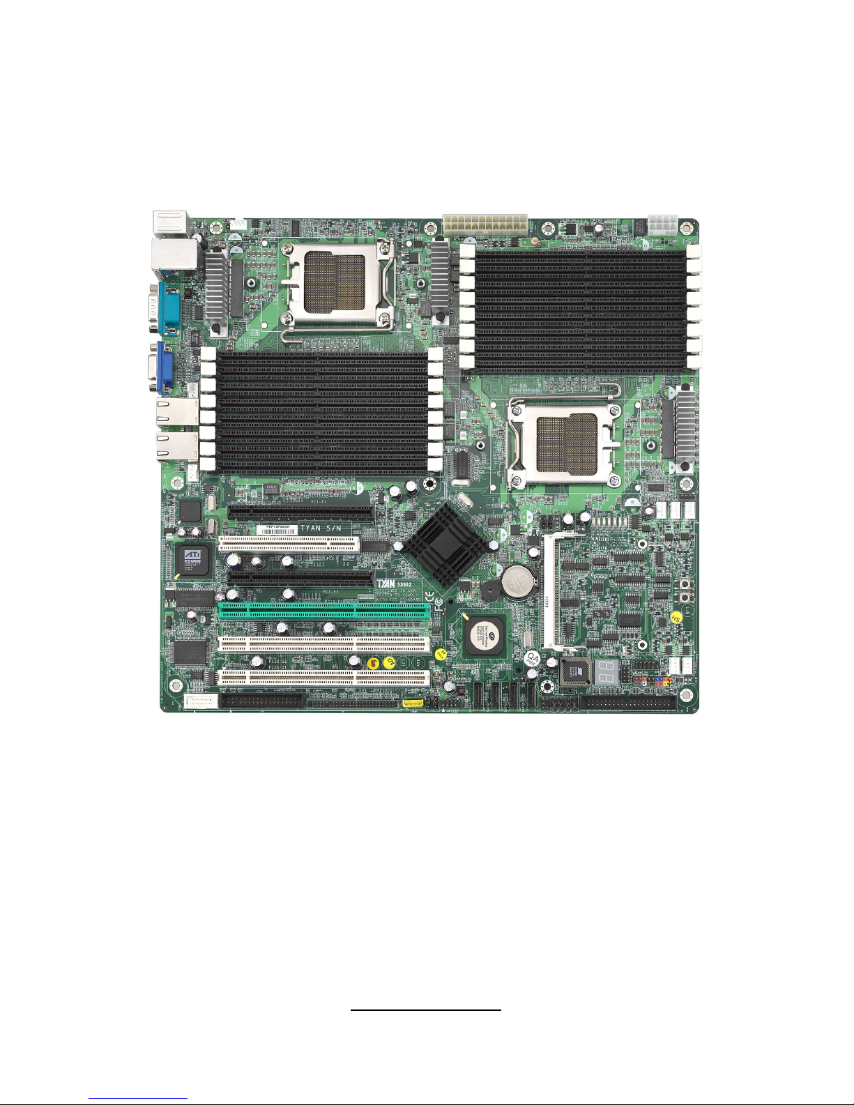
Expansion Slots
•Two (2) PCI Express X16 slots (each
w/ x8 signal)
•Two (2) PCI-X 133/100MHz slots
•One (1) PCI-X 100MHz slot
•One (1) PCI 32-bit/33MHz, v2.3
compliant slot
•One (1) TYAN “TARO” SO-DIMM
socket
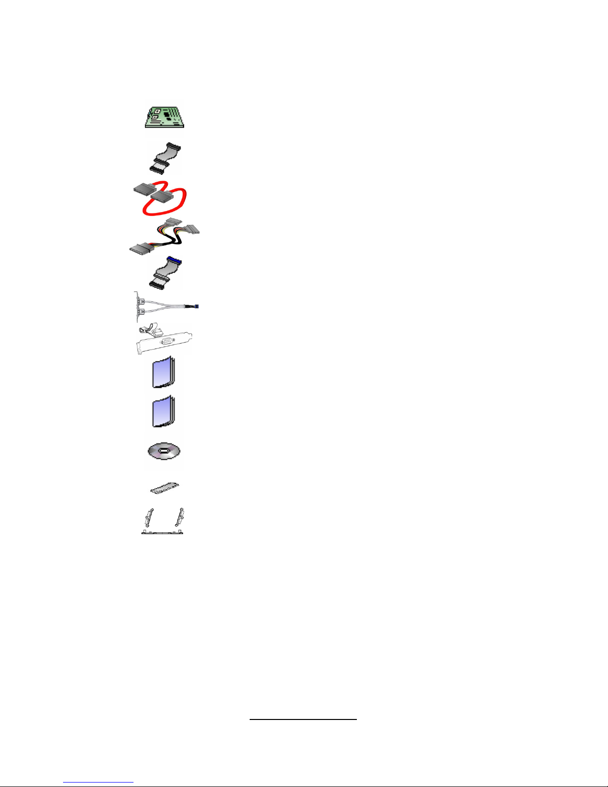
Integrated I/O
•One floppy connector
•One IDE connector
•Four SATA connectors
•Four USB2.0 ports (2 at rear, 2 via
cable)
•Two COM ports (1 at rear, 1 via cable)
•Tyan 2 x 9 front panel pin header
•Tyan 2 x 6 front panel pin header for
LAN/ID LED
•Tyan 2 x 7 pin header (2.0mm) for
FAN tachometer and PWM
•2 x 25 connector for optional TYAN
IPMI SMDC
Back Panel I/O Ports
•Stacked PS/2 Mouse & Keyboard
ports
•Stacked 2 USB ports and 1 10/100
RJ45 port
•One 9-pin COM port
•One 15-pin VGA connector
•Two side-by-side RJ-45 ports
Form Factor
•Extended ATX footprint (13” x 12”)
•EPS12V/ATX 12V universal power
connectors
Integrated LAN Controllers
•Dual GbE LAN (from BCM 5780)
- Embedded in BCM5780
- Two 10/100/1000 RJ-45 LAN ports
w/LED
•One Intel i82551 QM fast Ethernet
controller
- One 10/100 RJ-45 LAN port w/LED
- Operating on 32bit/33MHz PCI bus
Optional Modules
•M3291, IPMI 2.0 Remote System
Mgmt card
- Renesas H8S2167 BMC controller
- BT, KCS, Logging support
- IPMI-over-LAN
- Remote power on/off and reset
•M7901/M7902, Ultra 320 SCSI TARO
card
- Adaptec AIC-7901/7902 single/dual-
channel Ultra320 SCSI controller
- Adaptec Host RAID 0, 1, 10 supported
•M9000 SAS/SATA II TARO card
- Adaptec AIC-9405/9410 SAS
controller
- Supports up to 4-port (M9000-5) and
8-port (M9000-10) SAS & SATA running
at 3.0Gb/s
- Adaptec HostRAID 0, 1 & 10
supported
Power
•Onboard dual 4-phase VRM
•EPS12V/SSI v3.51 (24+8) power
connectors
Regulatory
•FCC Class B (DoC)
•European Community CE (DoC)


 User manual")