manuals.online logo
Brands
  1. Home
  2. •
  3. Brands
  4. •
  5. Tyco Electronics
  6. •
  7. Crimping Tools
  8. •
  9. Tyco Electronics CERTI-CRIMP II User manual

Tyco Electronics CERTI-CRIMP II User manual

Instruction Sheet
CERTI-CRIMP* II Handle
Assembly for Large Dies 408-10176
LOC B
1
of 3
E
2007 yco Electronics Corporation, Harrisburg, PA
All International Rights Reserved
E logo and yco Electronics are trademarks.
* rademark. Other products, logos, and company names used are the property of their respective owners.
OOLING ASSIS ANCE CEN ER 1-800-722-1111
PRODUC INFORMA ION 1-800-522-6752 his controlled document is subject to change.
For latest revision and Regional Customer Service,
visit our website at
www.ty oele troni s. om
05 DEC 07 Rev A
#16 AWG Max.
PROPER USE GUIDELINES
Cumulative raumaDisorderscanresultfromtheprolongeduseofmanuallypoweredhandtools.Handtoolsareintendedforoccasionaluseandlowvolume
applications. A wide selection of powered application equipment for extended-use, production operations is available.
Figure 1
Handles
Head
Moving Die Holder
Stationary Die Holder
1. INTRODUCTION
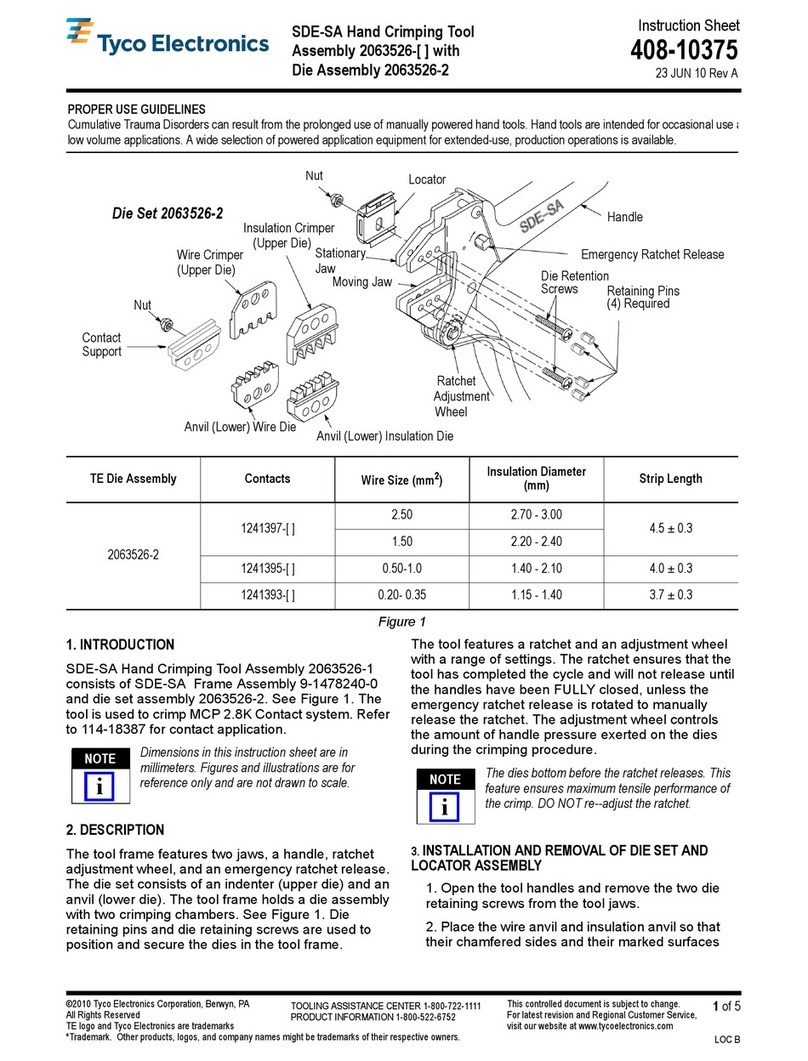
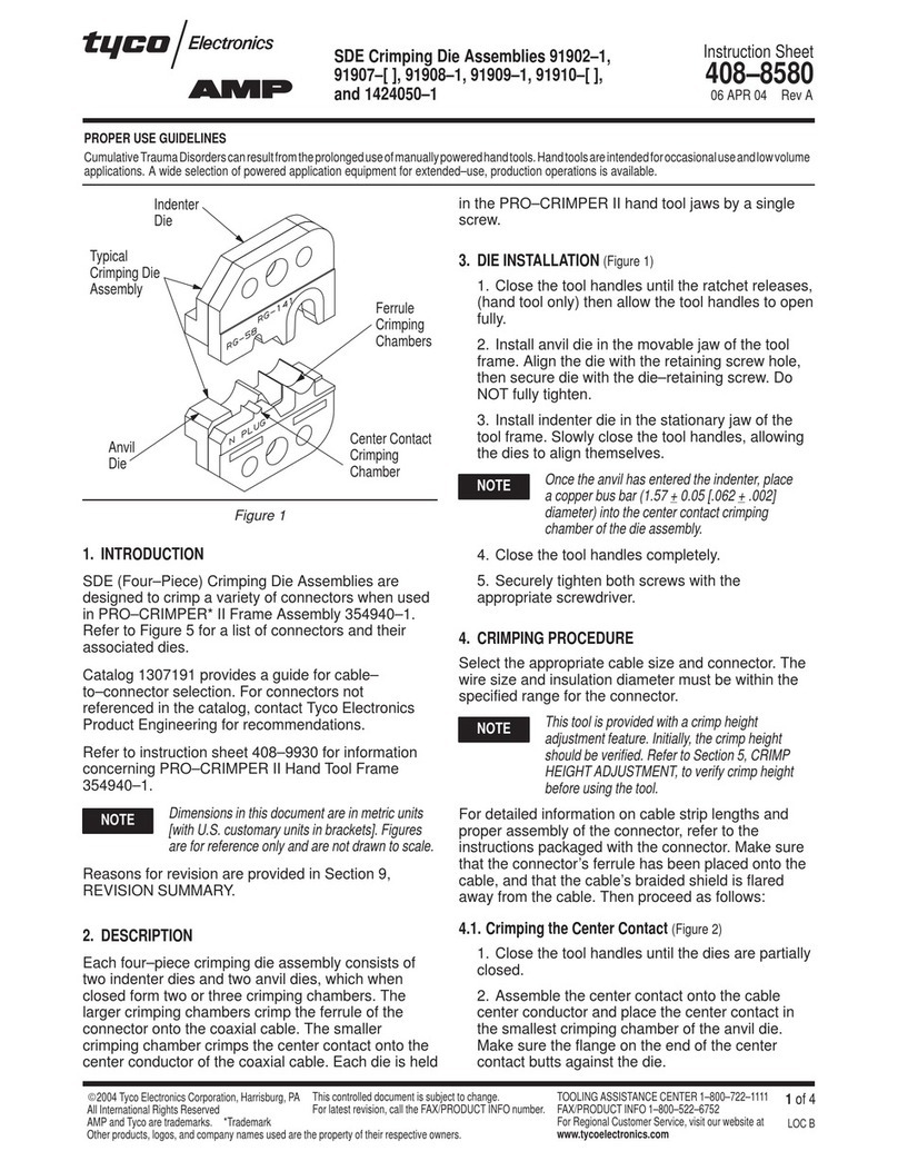
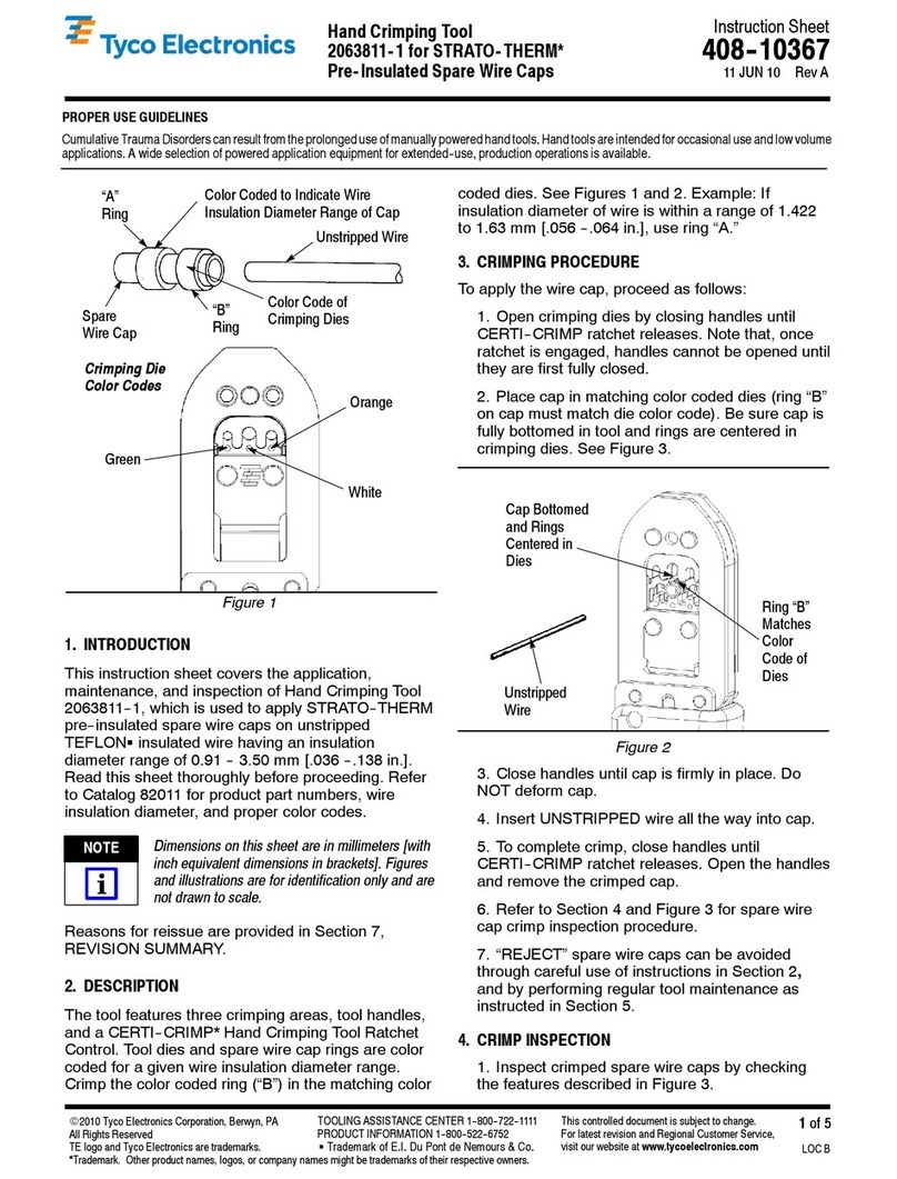
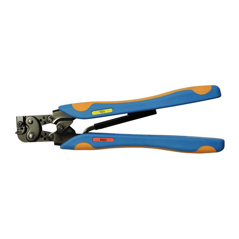
CERTI–CRIMP II Die Set Hand Tool 1901260–1 uses
interchangeable crimping dies and is used to crimp a
wide variety of products. These instructions are
general information only. Refer to the instruction
sheets packaged with the dies for specific crimping
instructions.
Dimensions in this instruction sheet are in
millimeters [with inches in brackets]. Figures and
illustrations are for reference only and are not
drawn to scale.
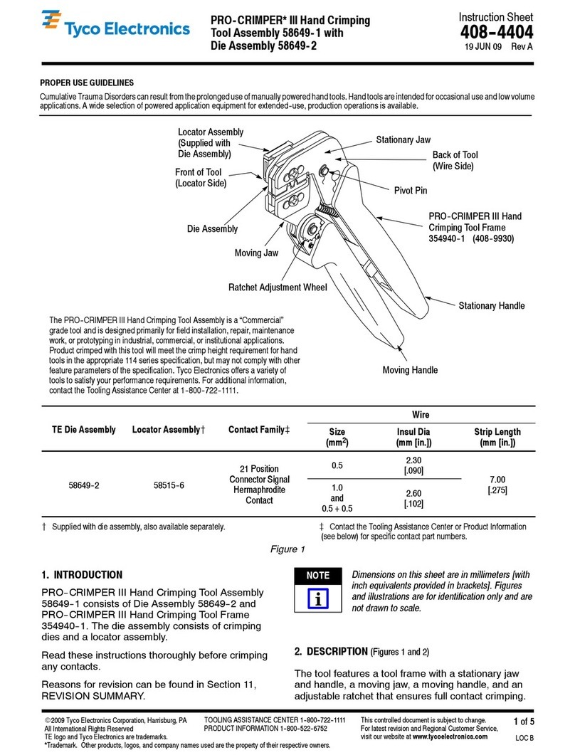
2. DESCRIPTION
(Figure 1)
The tool consists of a head with a stationary die
holder and moving die holder and handles with a
ratchet.
This tool is a member of the CERTI–CRIMP II hand
crimping tool family. The ratchet on this tool ensures
full crimping of the product. Once engaged, the
ratchet will not release until the handles have been
FULLY closed.
The crimping dies bottom before the ratchet
releases. This feature ensures ma imum
electrical and tensile performance of the crimp.
DO NOT re-adjust the ratchet.
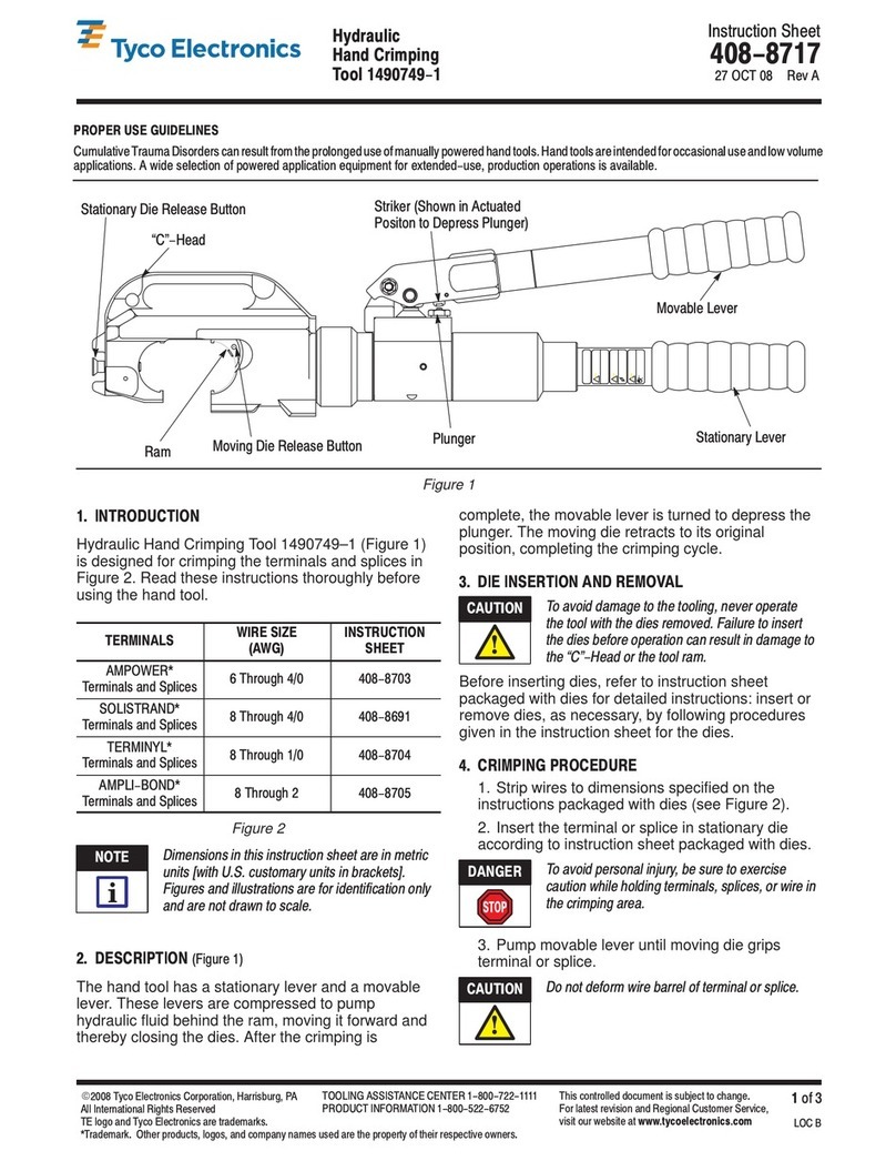
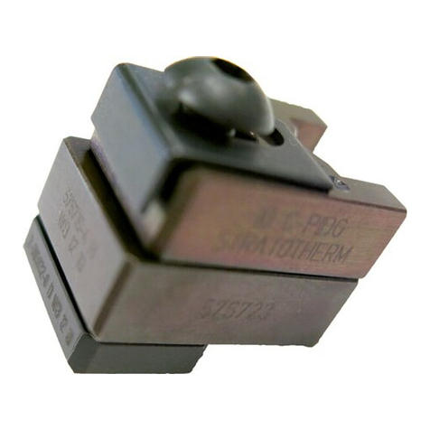
Each set of dies consists of a moving die and a
stationary die. Most moving dies have square corners
and the stationary dies have chamfered corners. See
Figure 2. Exceptions to this feature will be shown on
the instruction sheet packaged with the dies.
Figure 2
Typical Crimping Dies
Stationary
Die
Locator
Die Holding Screw
Insulation
Adjustment
Spacers
Moving Die
NOTE
i
CAUTION
!
408-10176
CERTI-CRIMP II H ndle Assembly for L rge Dies #16 AWG M x.
Rev
A2
of 3 Tyco Electronics Corporation
3. DIE INSERTION AND REMOVAL
If the crimping dies require an insulation adjustment,
refer to the instruction sheet packaged with dies for
the adjustment procedure, then proceed as follows:
1. Close the handles until the ratchet releases.
Allow the handles to open.
2. Place the stationary die in the stationary die
holder. Turn the die holding screw enough to hold
the die in place. DO NOT tighten the screw.
3. Place the moving die in the moving die holder.
Turn die holding screw enough to hold die in place.
DO NOT tighten the screw.
4. For crimping dies with only one crimping
chamber, align the dies, then tighten the die
holding screws.
5. For crimping dies with more than one crimping
chamber, proceed with the following:
a. Position the stationary die in the stationary
die holder. Tighten the die holding screw just
enough to hold the die in place. DO NOT tighten
the screw.
b. Position the moving die in the moving die
holder. Tighten the die holding screw just
enough to hold the die in place. DO NOT tighten
the screw.
c. With a terminal in position, insert a properly
stripped wire, then squeeze the handles until the
dies bottom.
d. Tighten both the die holding screws while the
dies are bottomed.
e. Remove the terminal from the dies.
6. To remove the dies, close the tool handles until
the ratchet releases, allow the handles to open,
loosen the die holding screws, and remove the
dies.
4. CRIMPING PROCEDURE
The following crimping procedure is typical for
most crimping dies used in this tool. Always refer
to instruction sheet packaged with the dies for
wire preparation and crimping procedure.
1. Place the terminal or splice in the crimping
chamber of the stationary die according to the
instructions included with the crimping dies.
2. Close the tool handles until the terminal or splice
is held firmly in place.
3. For a terminal, insert a properly stripped wire
into the wire barrel until the wire butts against the
crimping die locator.
For a splice, insert a properly stripped wire into the
wire barrel until the wire butts against the splice
wire stop.
4. Holding the wire in place, squeeze the tool
handles together until the ratchet releases. Allow
the handles to open FULLY, and remove the
crimped terminal or splice.
5. For a splice, re–position the splice according to
the instructions included with the crimping dies.
5. MAINTENANCE AND INSPECTION
It is recommended that a maintenance and inspection
program be performed periodically to ensure
dependable and uniform terminations. Though
recommendations call for at least one inspection a
month, frequency of inspection depends on:
1. The care, amount of use, and handling of the
tool.
2. The presence of abnormal amounts of dust and
dirt.
3. The degree of operator skill.
4. Your own established standards.
The tool is inspected before being shipped; however,
it is recommended that the tool be inspected
immediately upon arrival to ensure that the tool has
not been damaged during shipment.
5.1. D ily M inten nce
1. Immersed the tool (handles partially closed) in a
reliable commercial degreasing compound to
remove accumulated dirt, grease, and foreign
matter. When degreasing compound is not
available, the tool may be wiped clean with a soft,
lint–free cloth. DO NOT use hard or abrasive
objects that could damage the tool.
2. Make certain that the retaining pins are in place
and that they are secured with retaining rings.
3. All pins, pivot points, and bearing surfaces
should be protected with a THIN coat of any good
SAE 20 motor oil. DO NOT oil excessively.
4. When the tool is not in use, keep the handles
closed to prevent objects from becoming lodged in
the crimping dies. Store the tool in a clean, dry
area.
5.2. Periodic Inspection
A. Lubric tion
Lubricate all pins, pivot points, and bearing surfaces
with any good SAE 20 motor oil as follows:
Tool used in daily production — daily
Tool used daily (occasional) — weekly
Tool used weekly — monthly
NOTE
i
408-10176
CERTI-CRIMP II Handle Assembly for Large Dies #16 A G Max.
3
of 3Rev
A
Tyco Electronics Corporation
Wipe excess oil from the tool, particularly from the
crimping area. Oil transferred from the crimping area
onto certain terminations may affect the electrical
characteristics of an application.
B. Visual Inspection
1. Close the tool handles until the ratchet releases
and then allow them to open freely. If they do not
open quickly and fully, the spring is defective and
must be replaced. See Section 6, REPLACEMENT
AND REPAIR.
2. Inspect the head for worn, cracked, or broken
crimping dies. If damage is evident, return the tool
for evaluation and repair. See Section 6,
REPLACEMENT AND REPAIR.
3. Check die alignment and tighten the die holding
screws at least twice daily while tool is in use.
5.3. Ratchet Inspection
Check the ratchet to ensure that the ratchet does not
release prematurely, allowing the dies to open before
they have fully bottomed. Proceed as follows:
1. Remove traces of oil or dirt from the bottoming
surfaces of the dies.
2. Obtain a 0.025 mm [.001 in.] shim that is
suitable for checking the clearance between the
bottoming surfaces of the dies.
3. Select a terminal or splice and
maximum
size
wire for the terminal or splice.
4. Position the terminal or splice in the crimping
chamber according to according to the instructions
included with the crimping dies. Holding the wire in
place, squeeze the tool handles together until the
ratchet releases. Hold the tool handles in this
position, maintaining just enough pressure to keep
the dies closed.
5. Check the clearance between the bottoming
surfaces of the dies. If the clearance is 0.025 mm
[.001 in.] or less, the ratchet is satisfactory. If
clearance exceeds 0.025 mm [.001 in.], the ratchet
is out of adjustment and must be repaired. See
Section 6, REPLACEMENT AND REPAIR.
6. REPLACEMENT AND REPAIR
Customer–replaceable parts are listed in Figure 3.
A complete inventory should be stocked and
controlled to prevent lost time when replacement of
parts is necessary. Parts other than those listed
should be replaced by Tyco Electronics to ensure
quality and reliability. Order replacement parts
through your representative, or call 1–800–526–5142,
or send a facsimile of your purchase order to
717–986–7605, or write to:
CUSTOMER SERVICE (038–035)
TYCO ELECTRONICS CORPORATION
PO BOX 3608
HARRISBURG PA 17105–3608
For customer repair service, call 1–800–526–5136.
7. REVISION SUMMARY
S
Initial release of document
296.93 [11.690 Approx.
70.36
[2.770
1 2
3 4
REPLACEMENT PARTS
ITEM PART NUMBER DESCRIPTION QTY PER TOOL
1 1901610-1 DIE HOLDER, Lower 1
2 1-21003-9 SCREW, FLT, Soc Hd Cap 6-32 x .375 LG 1
3 1490759-1 PIN, Grooved 2
4 1428191-3 RING, Retaining 4
Figure 3

This manual suits for next models

1

Other Tyco Electronics Crimping Tools manuals

Tyco Electronics PRO-CRIMPER III 58603-1 User manual

Tyco Electronics

Tyco Electronics PRO-CRIMPER III 58603-1 User manual

Tyco Electronics 69067 User manual

Tyco Electronics

Tyco Electronics 69067 User manual

Tyco Electronics 58443-1 User manual

Tyco Electronics

Tyco Electronics 58443-1 User manual

Tyco Electronics 1752787-1 User manual

Tyco Electronics

Tyco Electronics 1752787-1 User manual

Tyco Electronics PRO-CRIMPER III User manual

Tyco Electronics

Tyco Electronics PRO-CRIMPER III User manual

Tyco Electronics PRO-CRIMPER III User manual

Tyco Electronics

Tyco Electronics PRO-CRIMPER III User manual

Tyco Electronics PRO-CRIMPER III User manual

Tyco Electronics

Tyco Electronics PRO-CRIMPER III User manual

Tyco Electronics PRO-CRIMPER III User manual

Tyco Electronics

Tyco Electronics PRO-CRIMPER III User manual

Tyco Electronics PRO-CRIMPER III User manual

Tyco Electronics

Tyco Electronics PRO-CRIMPER III User manual

Tyco Electronics STRATO-THERM 1-46673-0 User manual

Tyco Electronics

Tyco Electronics STRATO-THERM 1-46673-0 User manual

Tyco Electronics 2-231652-1 User manual

Tyco Electronics

Tyco Electronics 2-231652-1 User manual

Tyco Electronics 2063195-1 User manual

Tyco Electronics

Tyco Electronics 2063195-1 User manual

Tyco Electronics 2063811-1 User manual

Tyco Electronics

Tyco Electronics 2063811-1 User manual

Tyco Electronics 90035-3 User manual

Tyco Electronics

Tyco Electronics 90035-3 User manual

Tyco Electronics PRO-CRIMPER III 58564-1 User manual

Tyco Electronics

Tyco Electronics PRO-CRIMPER III 58564-1 User manual

Tyco Electronics 603995 Series User manual

Tyco Electronics

Tyco Electronics 603995 Series User manual

Tyco Electronics 1213850-1 User manual

Tyco Electronics

Tyco Electronics 1213850-1 User manual

Tyco Electronics 58649-1 User manual

Tyco Electronics

Tyco Electronics 58649-1 User manual

Tyco Electronics PRO-CRIMPER III User manual

Tyco Electronics

Tyco Electronics PRO-CRIMPER III User manual

Tyco Electronics PRO-CRIMPER III User manual

Tyco Electronics

Tyco Electronics PRO-CRIMPER III User manual

Tyco Electronics 408-10050 User manual

Tyco Electronics

Tyco Electronics 408-10050 User manual

Tyco Electronics ROTA-CRIMP 68321-1 User manual

Tyco Electronics

Tyco Electronics ROTA-CRIMP 68321-1 User manual

Tyco Electronics PRO-CRIMPER III User manual

Tyco Electronics

Tyco Electronics PRO-CRIMPER III User manual

Tyco Electronics 1490749-1 User manual

Tyco Electronics

Tyco Electronics 1490749-1 User manual

Popular Crimping Tools manuals by other brands

Kingfisher 5059340003733 manual

Kingfisher

Kingfisher 5059340003733 manual

TE Connectivity 46447 instruction sheet

TE Connectivity

TE Connectivity 46447 instruction sheet

JST CS 10-WC-SF1002 instruction manual

JST

JST CS 10-WC-SF1002 instruction manual

Greenlee GATOR EK622PLX Operation manual

Greenlee

Greenlee GATOR EK622PLX Operation manual

Legend MSS-KREC-54AC SAFE OPERATION & MAINTENANCE INSTRUCTIONS

Legend

Legend MSS-KREC-54AC SAFE OPERATION & MAINTENANCE INSTRUCTIONS

Greenlee GATOR EK1550LX Operation manual

Greenlee

Greenlee GATOR EK1550LX Operation manual

HRS HT601/TM21P-88P operating instructions

HRS

HRS HT601/TM21P-88P operating instructions

molex 207129 Series Operating Instruction and Specifications Sheet

molex

molex 207129 Series Operating Instruction and Specifications Sheet

Ilsco TASKMASTER TB-6DF1000-P instruction manual

Ilsco

Ilsco TASKMASTER TB-6DF1000-P instruction manual

Greenlee GATOR EK628 instruction manual

Greenlee

Greenlee GATOR EK628 instruction manual

Hilti NUN 054 IE-A22 Original operating inctructions

Hilti

Hilti NUN 054 IE-A22 Original operating inctructions

Gates GC16XD Safety and operating manual

Gates

Gates GC16XD Safety and operating manual

molex 63827-9300 manual

molex

molex 63827-9300 manual

Panduit PBTMT quick start guide

Panduit

Panduit PBTMT quick start guide

JST CS 10 - WC 122 instruction manual

JST

JST CS 10 - WC 122 instruction manual

Huskie Tools REC-3410 Operating instructions manual

Huskie Tools

Huskie Tools REC-3410 Operating instructions manual

WIREFY WIREFY-CRMP-A5 manual

WIREFY

WIREFY WIREFY-CRMP-A5 manual

TE Connectivity 1-45216-0 instruction sheet

TE Connectivity

TE Connectivity 1-45216-0 instruction sheet

manuals.online logo
manuals.online logoBrands
  • About & Mission
  • Contact us
  • Privacy Policy
  • Terms and Conditions

Copyright 2025 Manuals.Online. All Rights Reserved.