manuals.online logo
Brands
  1. Home
  2. •
  3. Brands
  4. •
  5. Tyco Electronics
  6. •
  7. Crimping Tools
  8. •
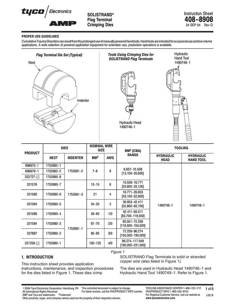
  9. Tyco Electronics PRO-CRIMPER III User manual

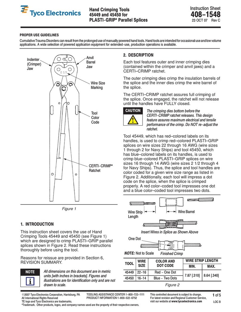
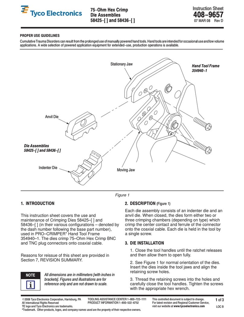
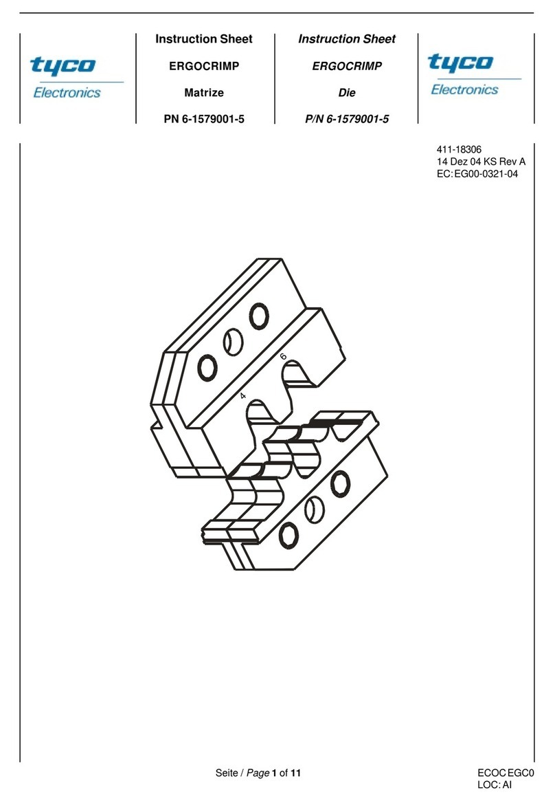
Tyco Electronics PRO-CRIMPER III User manual

Instruction Sheet
PRO- CRIMPER* III Hand Crimping Tool
Assembly 58663- 1 and Die Assembly 408--4476
LOC B
1of 4
E2009 Tyco Electronics Corporation, Harrisburg, PA
All International Rights Reserved
TE logo and Tyco Electronics are trademarks.
*Trademark. Other products, logos, and company names used are the property of their respective owners.
TOOLING ASSISTANCE CENTER 1--800--722--1111
PRODUCT INFORMATION 1--800--522--6752
This controlled document is subject to change.
For latest revision and Regional Customer Service,
visit our website at www.tycoelectronics.com
17 DEC 09 Rev B58663- 2 For Series F Coaxial Connectors
PROPER USE GUIDELINES
Cumulative Trauma Disorders can result from the prolonged use of manually powered hand tools. Hand tools are intended for occasional use and low volume
applications. A wide selection of powered application equipment for extended--use, production operations is available.
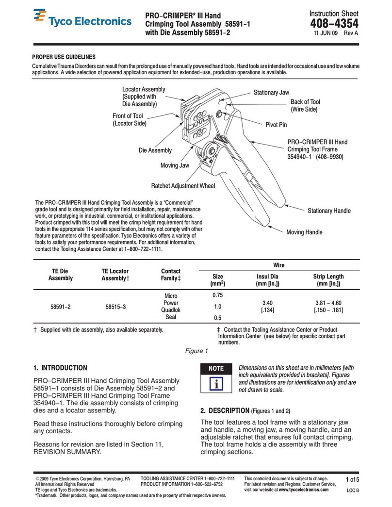
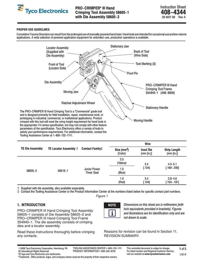
Figure 1
The PRO--CRIMPER III Hand Crimping Tool is a “Commercial” grade
tool and is designed primarily for field installation, repair, maintenance
work, or prototyping in industrial, commercial, or institutional applications.
Product crimped with this tool will meet the crimp height requirement for
hand tools in the appropriate 114 series specification, but may not comply
with other feature parameters of the specification. Tyco Electronics offers a
variety of tools to satisfy your performance requirements. For additional
information, contact the Tooling Assistance Center at 1--800--722--1111.
Die Assembly
58663--2
Moving Jaw
Ratchet Adjustment
Wheel
Moving
Handle
Stationary
Handle
PRO--CRIMPER III Hand
Crimping Tool Frame
354940--1 (408--9930)
Pivot Pin
Back of Tool
(Wire Side)
Stationary Jaw
1. INTRODUCTION
PRO--CRIMPER III Hand Crimping Tool Assembly
58663--1 consists of Die Assembly 58663--2 and
PRO--CRIMPER III Hand Crimping Tool Frame
354940--1. The tool is designed to crimp Series F
coaxial connectors onto cable Series 6 Quad.
Dimensions on this sheet are in millimeters
[with inch equivalents in brackets]. Figures and
illustrations are for identification only and are not
drawn to scale.
For additional information on the hand tool frame,
refer to 408--9930. For the selection of Series F
coaxial connectors, contact AMP Product Engineering
for connector recommendations.
Reasons for reissue of this instruction sheet are
provided in Section 8, REVISION SUMMARY.
2. DESCRIPTION (Figure 1)
The tool features a tool frame with a stationary jaw
and handle, a moving jaw, a moving handle, and an
adjustable ratchet that ensures full connector
crimping. The tool frame holds the die assembly.
The die assembly features an anvil and a nest
containing a hex crimping cavity. Each die is held in
the hand tool by a single screw.
3. INSTALLATION AND REMOVAL OF THE
DIE ASSEMBLY (Figure 2)
1. Open the tool handles and remove the two die
retaining screws from the tool jaws.
2. Slide the die assembly into the partially opened
tool jaws.
3. Insert the die retaining screws and tighten the
screws just enough to hold the dies in place. Do
not tighten the screws completely at this time.
NOTE
i
408- 4476
PRO- CRIMPER III Hand Crimping Tool Assembly 58663- 1 for Series F Coaxial Connectors
Rev B2 of 4 Tyco Electronics Corporation
Figure 2
Tool Frame
Die Retaining
Screws
Anvil Die
Nest Die
4. Carefully close the tool handles, making sure
the dies align properly. Continue closing the tool
handles until the ratchet in the tool frame has
engaged sufficiently to hold the die in place, then
tighten both die retaining screws.
5. To disassemble, close the tool handles until the
ratchet releases, remove the two die retaining
screws, and slide the dies out of the tool jaws.
4. CRIMPING PROCEDURE
Before using the tool, the crimping chamber and
tool ratchet should be inspected as specified in
Paragraph 5.2, Measuring Die Opening, and
Paragraph 5.3, Ratchet Adjustment.
Strip cable according to the proper dimensions and
assemble the connector to the cable according to the
instructions in the appropriate connector instruction
sheet. Then proceed as follows:
1. Place connector in the nest die so that the
shoulder on the connector is approximately
3.18 [.125] from the edge of the die. See Figure 3.
2. Holding the assembly in place, close the tool
handles until the ratchet releases.
3. Remove the crimped assembly from the
crimping die.
5. INSPECTION
5.1. Visual Inspection
Inspection of the crimping dies should be made on a
regular basis to ensure that they have not become
worn or damaged. Inspect the crimp sections for
flattened, chipped, worn, or broken areas. If damage
or abnormal wear is evident, the dies must be
replaced. Refer to Section 7, REPLACEMENT.
5.2. Measuring Die Opening
The die assembly will perform correctly as long as:
(1) the product specified is correct for the application,
(2) the specific die assembly is used, (3) the die
assembly has been measured to ensure that the
opening is correct, and (4) the tool has been adjusted
correctly.
Figure 3
Connector Approximately
3.18 [.125] from Edge of Die
Connector in
Nest Die
NOTE
i
408- 4476
PRO- CRIMPER III Hand Crimping Tool Assembly 58663- 1 for Series F Coaxial Connectors
3of 4Rev BTyco Electronics Corporation
5.3. Measuring Die Opening
The die assembly will perform correctly as long as:
(1) the product specified is correct for the application,
(2) the specific die assembly is used, (3) the die
assembly has been measured to ensure that the
opening is correct, and (4) the tool has been adjusted
correctly.
Figure 4 provides information on die opening size.
Figure 4
9.14
[.360]
Dies
Bottomed
5.4. Ratchet Adjustment (Figure 5)
The ratchet mechanism features an adjustment wheel
with eight settings. The adjustment wheel controls the
amount of handle pressure exerted on the tool jaws
and crimping dies during crimping. If the crimp is not
acceptable, adjust the ratchet as follows:
1. Sufficiently loosen the screw at the ratchet
adjustment wheel so that the wheel can be rotated
above the post that engages the teeth in the wheel.
2. If the crimp is too loose, turn the wheel to a
higher notch (for example, if the wheel is set at
notch 5, move the wheel to notch 6). If the crimp is
too tight, move the wheel to a lower notch.
3. Tighten the screw at the ratchet adjustment
wheel.
If the crimp cannot be made to conform to the
dimensions provided in the appropriate product
application specification, the tool and/or dies are
defective and must be replaced.
Other dies for PRO--CRIMPER III hand tool
frames may be used in this tool; however, the
ratchet adjustment wheel may require adjustment
to achieve acceptable crimp height.
Figure 5
Screwdriver
Ratchet Adjustment
Wheel
Lockscrew
6. MAINTENANCE
Ensure that the tool and dies are clean by wiping
them with a clean, soft cloth. Remove any debris with
a clean, soft brush. Do not use objects that could
damage the tool. When not in use, keep handles
closed to prevent objects from becoming lodged in
the dies, and store in a clean, dry area.
7. REPLACEMENT
Customer--replaceable parts are shown in Figure 1.
Available separately, PRO--CRIMPER III Hand Tool
Repair Kit 679221--1 includes a replacement nut and
a variety of pins, rings, screws, and springs.
If the dies are damaged or worn excessively, they
must be replaced.
Order the repair kit and replaceable parts through
your Tyco Electronics representative, or call
1--800--526--5142, or send a facsimile of your
purchase order to 717--986--7605, or write to:
CUSTOMER SERVICE (038--035)
TYCO ELECTRONICS
PO BOX 3608
HARRISBURG PA 17105--3608
8. REVISION SUMMARY
Revisions to this instruction sheet include:
SPRO--CRIMPER II Hand Tool to
PRO--CRIMPER III Hand Tool;
SApplied TE logo;
SUpdated format; and
SAdded back page to show the tooling
compatible with 58663--2.
NOTE
i
408- 4476
PRO- CRIMPER III Hand Crimping Tool Assembly 58663- 1 for Series F Coaxial Connectors
Rev B4 of 4 Tyco Electronics Corporation
Figure 6
PRO-CRIMPER III Hand Tool 354940-1
(Instruction Sheet 408- 9930)
SDE- SA Hand Tool 9- 1478240-0
(Instruction Sheet 408- 8851)
SDE Bench Terminator 1490076-2
(Customer Manual 409- 10052)
626 Adapter 679304- 1
(Instruction Sheet 408- 4070)
Battery Tool (Shouldered Die) 1725837-1, -2
(Customer Manual 409- 10053)
Battery Tool (Pin/Shoulder Die) 1213890-1, -2
(Customer Manual 409- 10065)
Since crimped splices cannot be
removed from this tool, DO NOT
crimp splices in this battery tool.
NOTE
i

This manual suits for next models

1

Other Tyco Electronics Crimping Tools manuals
Tyco Electronics PIDG STRATO-THERM User manual

Tyco Electronics

Tyco Electronics PIDG STRATO-THERM User manual

Tyco Electronics STRATO-THERM 1-46673-0 User manual

Tyco Electronics

Tyco Electronics STRATO-THERM 1-46673-0 User manual

Tyco Electronics 46121 User manual

Tyco Electronics

Tyco Electronics 46121 User manual

Tyco Electronics 1490749-1 User manual

Tyco Electronics

Tyco Electronics 1490749-1 User manual

Tyco Electronics 1804834-1 User manual

Tyco Electronics

Tyco Electronics 1804834-1 User manual

Tyco Electronics 48858-1 User manual

Tyco Electronics

Tyco Electronics 48858-1 User manual

Tyco Electronics PRO-CRIMPER III User manual
Tyco Electronics

Tyco Electronics PRO-CRIMPER III User manual
Tyco Electronics PRO-CRIMPER III 58603-1 User manual

Tyco Electronics

Tyco Electronics PRO-CRIMPER III 58603-1 User manual

Tyco Electronics 408-10050 User manual

Tyco Electronics

Tyco Electronics 408-10050 User manual

Tyco Electronics PRO-CRIMPER III User manual

Tyco Electronics

Tyco Electronics PRO-CRIMPER III User manual

Tyco Electronics PRO-CRIMPER III User manual

Tyco Electronics

Tyco Electronics PRO-CRIMPER III User manual

Tyco Electronics 58605-1 User manual

Tyco Electronics

Tyco Electronics 58605-1 User manual

Tyco Electronics PRO-CRIMPER III User manual

Tyco Electronics

Tyco Electronics PRO-CRIMPER III User manual

Tyco Electronics PRO- CRIMPER III User manual

Tyco Electronics

Tyco Electronics PRO- CRIMPER III User manual

Tyco Electronics PRO-CRIMPER III User manual

Tyco Electronics

Tyco Electronics PRO-CRIMPER III User manual

Tyco Electronics PRO-CRIMPER III User manual

Tyco Electronics

Tyco Electronics PRO-CRIMPER III User manual

Tyco Electronics PRO-CRIMPER III User manual

Tyco Electronics

Tyco Electronics PRO-CRIMPER III User manual

Tyco Electronics 2063811-1 User manual

Tyco Electronics

Tyco Electronics 2063811-1 User manual

Tyco Electronics PRO-CRIMPER III User manual

Tyco Electronics

Tyco Electronics PRO-CRIMPER III User manual

Tyco Electronics ERGOCRIMP 2-1579021-9 User manual

Tyco Electronics

Tyco Electronics ERGOCRIMP 2-1579021-9 User manual

Tyco Electronics CERTI-CRIMP II User manual

Tyco Electronics

Tyco Electronics CERTI-CRIMP II User manual

Tyco Electronics SDE-SA 2063526 Series User manual

Tyco Electronics

Tyco Electronics SDE-SA 2063526 Series User manual

Tyco Electronics PRO-CRIMPER III User manual
Tyco Electronics

Tyco Electronics PRO-CRIMPER III User manual
Tyco Electronics 2063195-1 User manual

Tyco Electronics

Tyco Electronics 2063195-1 User manual

Popular Crimping Tools manuals by other brands

CRH CRL CBLHCT1 instruction manual

CRH

CRH CRL CBLHCT1 instruction manual

molex 207129 Series Specification sheet
molex

molex 207129 Series Specification sheet

Staubli CT-CZ/POF operating instructions

Staubli

Staubli CT-CZ/POF operating instructions

molex 207129 Series specification

molex

molex 207129 Series specification

Greenlee GATOR EK1550LX Operation manual

Greenlee

Greenlee GATOR EK1550LX Operation manual

Cembre TC025 Operation and maintenance manual

Cembre

Cembre TC025 Operation and maintenance manual

Westward 13H894 Operating instructions and parts manual

Westward

Westward 13H894 Operating instructions and parts manual

molex 63811-9370 Specification sheet

molex

molex 63811-9370 Specification sheet

TE Connectivity CERTI- CRIMP Series instruction sheet

TE Connectivity

TE Connectivity CERTI- CRIMP Series instruction sheet

TE Connectivity 2063525-1 instruction sheet

TE Connectivity

TE Connectivity 2063525-1 instruction sheet

PRECISETOOL XCXY-02 instructions

PRECISETOOL

PRECISETOOL XCXY-02 instructions

TE Connectivity CERTI-CRIMP II 2381707-1 instruction sheet

TE Connectivity

TE Connectivity CERTI-CRIMP II 2381707-1 instruction sheet

Cembre B1320 Operation and maintenance manual

Cembre

Cembre B1320 Operation and maintenance manual

FCI HT-0525 manual

FCI

FCI HT-0525 manual

Trick-tools Roper Whitney 0585 Operation, parts & maintenance manual

Trick-tools

Trick-tools Roper Whitney 0585 Operation, parts & maintenance manual

Emerson Klauke UAP332CFM manual

Emerson

Emerson Klauke UAP332CFM manual

JST CS 10 L-WC-SF371 instruction manual

JST

JST CS 10 L-WC-SF371 instruction manual

Textron Greenlee GATOR EK425L instruction manual

Textron

Textron Greenlee GATOR EK425L instruction manual

manuals.online logo
manuals.online logoBrands
  • About & Mission
  • Contact us
  • Privacy Policy
  • Terms and Conditions

Copyright 2025 Manuals.Online. All Rights Reserved.