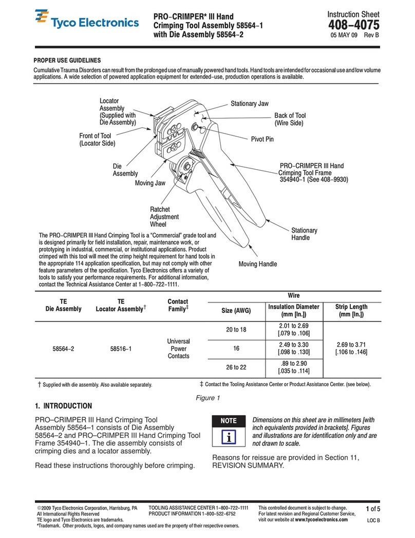
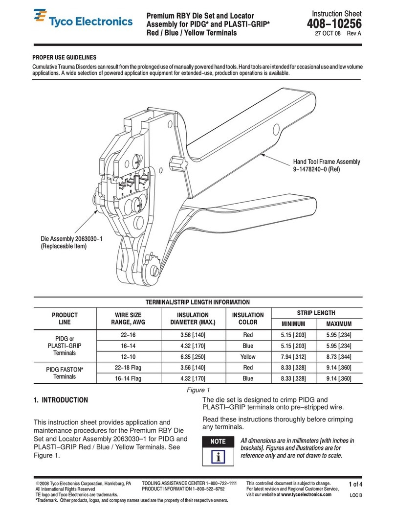
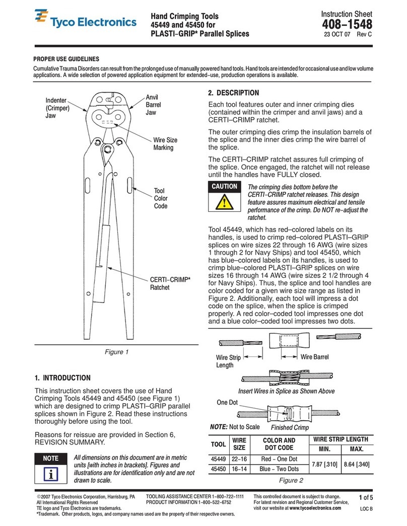
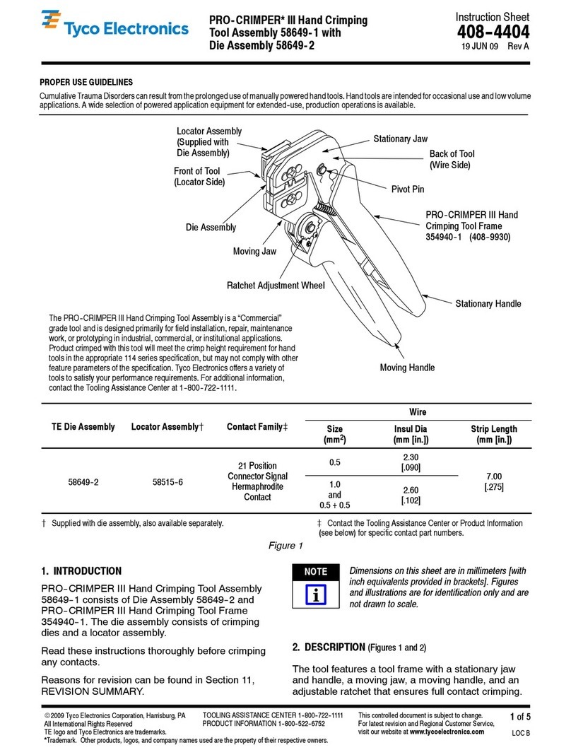
manuals.online logo
Brands
  1. Home
  2. •
  3. Brands
  4. •
  5. Tyco Electronics
  6. •
  7. Crimping Tools
  8. •
  9. Tyco Electronics DYNA-CRIMP User manual

Tyco Electronics DYNA-CRIMP User manual

Instruction heet
DYNA-CRIMP*
Crimping H ad 408-2450
(was I 2450)
LOC B
1
of 4
E
2008 Tyco Electronics Corporation, Harrisburg, PA
All International Rights Reserved
TE logo and Tyco Electronics are trademarks.
*Trademark. Other products, logos, and company names used are the property of their respective owners.
TOOLING A I TANCE CENTER 1-800-722-1111
PRODUCT INFORMATION 1-800-522-6752 This controlled document is subject to change.
For latest revision and Regional Customer ervice,
visit our website at
www.tyco l ctronics.com
20 MAY 08 Rev A
69051
Yoke
Cylinder
Head
Removable
Latch Pin
Cylinder
Dust Cap (Ref)
Quick-Disconnect
Coupling
Ram
Pivot
Pin
etscrew
DYNA-CRIMP
Crimping Head
69051
Figure 1
1. INTRODUCTION
This instruction sheet provides instructions on product
application and a Maintenance and Inspection
procedure for the DYNA–CRIMP Crimping Head
69051. This tool is used to crimp:
S
AMPLI–BOND* Terminals, wire sizes 8–2
AWG. See Instruction Sheet 408–1758.
S
PLASTI–GRIP* Terminals, wire sizes 8–2
AWG. See Instruction Sheets 408–1729 and
408–1758.
S
Pre–Insulated AMPOWER* Terminals, wire
size 2. See Instruction Sheet 408–1758.
S
COPALUM* Terminals and Splices, wire sizes
8–4 (inhibitor filled) AWG. See Instruction
Sheet 408–2134.
S
TERMINYL* Terminals and Splices, wire sizes
8–2 AWG. See Instruction Sheet 408–1729.
S
Pre–Insulated AMPOWER Terminals wire sizes
4–2 AWG. See Instruction Sheet 408–1729.
Basic instructions on the use of this crimping head
are provided in Section 2, INSTRUCTIONS. Section 3
contains a Maintenance and Inspection Procedure
required to establish and maintain a tool certification
program.
2. INSTRUCTIONS
2.1. Attaching th Crimping H ad
If a coupling component for the hose assembly is
packaged inside the quick-disconnect coupler on
the head, it is to be used to replace the coupling
on a hose assembly not equipped with a
quick-disconnect coupler.
Avoid personal injury. Release hydraulic pressure
to hose or handle control. Disconnect electric
power unit from power supply.
1. Thoroughly clean coupling area of handle
control or hose assembly and crimping head.
2. Remove protective (dust) caps.
3. Mate both quick–disconnect couplers and
tighten collar of coupler assembly on crimping
head. See Figure 1.
Oil flow must be unobstructed between power
unit and crimping head. Ensure that all couplers
are fully mated and tightened.
If a crimping head must be removed after power
unit was in operation, pressure must be released
in the hydraulic system. When using hydraulic
power unit 69120- ], DISCONNECT POWER
UNIT FROM POWER SUPPLY. When using
hydraulic hand pump 314979-1, make sure to
depress pressure release lever.
2.2. Di Ins rtion and R moval
Avoid personal injury. When using power unit,
exercise caution to avoid accidentally depressing
the foot switch or handle control when changing
dies.
A. Di Ins rtion
1. Remove latch pin and open yoke. See Figure 2.
NOTE
i
DANGER
CAUTION
!
NOTE
i
DANGER
408-2450
DYNA-CRIMP Crimping Head 69051
Rev
A2
of 4 Tyco Electronics Corporation
Figure 2
Yoke Set Scre
Large Shank on
Stationary Die
Small Shank on
Moving Die
Set Scre
Ram
Advanced
Latch Pin
Removed
Befo e dies a e inse ted, loosen the socket head
cap sc ews that hold the insulation c imping
section of the dies in place. If sc ews a e not
loosened, the dies may mot fit into the head of
the tool because of close clea ance. The
insulation c imp adjustment must be made
acco ding to the inst uction sheet packaged with
the dies.
2. Loosen set screw in yoke.
3. Insert stationary die (die with large shank) into
yoke as shown in Figure 2. Tighten the set screw.
4. Activate tool to advance ram until set screw is
visible.
5. Loosen set screw in ram and insert moving die
(die with small shank) into ram as shown in
Figure 2. Tighten set screw.
Be su e that moving die is p ope ly o iented with
stationa y die.
6. Return ram to the “down” position.
7. Close yoke and insert latch pin.
Ensu e that the latch pin is fully inse ted o
damage may occu to the yoke, dies, o latch pin.
B. Die Removal
1. Remove latch pin and open yoke.
2. Loosen set screw in yoke and remove stationary
die.
3. Raise ram to “full up” position. Loosen set screw
and remove moving die.
Latch pin kit 69709 is available as an accesso y
item. The latch pin is attached to the pivot pin by
a chain and the eby eliminates the possibility of
misplacing the latch pin.
2.3. Crimping Pro edure
Avoid pe sonal inju y. When ope ating powe unit,
exe cise caution while holding te minals, splices,
o wi e nea c imping a ea.
The following procedure provides only general
information concerning crimping. Refer to the
instruction material packaged with the dies and power
unit for more detailed information including wire
stripping dimensions and how to position terminals or
splices in the dies.
Neve ope ate the powe unit without having a
c imping head attached to the handle cont ol o
c imping head coupling.
1. Insert terminal or splice in stationary die
according to instructions packaged with the dies.
2. Activate power unit to advance dies and hold
terminal or splice in place.
3. Insert stripped wire into terminal or splice.
4. Activate power unit to complete the crimp.
3. MAINTENANCE/INSPECTION PROCEDURE
The following procedure includes information required
to disassemble, inspect, and repair the crimping
head. Tyco Electronics recommends that a
maintenance/inspection program be performed
periodically. Frequency of inspection is dependent
upon:
S
The care, amount of use, and handling of the
head
S
The type and size of the products crimped
S
The degree of operator skill
S
The presence of abnormal amounts of dust and
dirt.
All crimping heads are inspected before packaging.
Since there is a possibility of damage in shipment,
Tyco Electronics recommends that new heads be
inspected in accordance with Section 3 when
received in your plant. Refer to Paragraph 3.5 for
parts replacement information.
3.1. Cleaning
Remove accumulations of dirt and grease on the
crimping head, especially in the area where dies are
inserted. Clean entire head frequently with a clean
cloth.
NOTE
i
NOTE
i
CAUTION
!
NOTE
i
DANGER
CAUTION
!
408-2450
DYNA-CRIMP Crimping Head 69051
3
of 4Rev
A
Tyco Electronics Corporation
Figure 3
Check for
E cessive
Wear at
Pivot Pin
Check these
Areas for Cracks
Check for
E cessive
Wear at
Latch Pin
Check Die
Areas for
Damage
Check these
Areas for Cracks
Dust Cap (Ref)
3.2. Visual Inspe tion
Inspect ssembled he d for nicks, scr tches, nd
cr cks. Inspect for cr cks especi lly t corners of
yoke nd round the top cylinder. See Figure 3.
Inspect the pivot pin nd l tch pin holes for we r.
When the he d is dis ssembled, inspect met l
surf ces for nicks, cr cks, scr tches, nd
excessive we r, especi lly where sliding cont ct
occurs. Perform inspection s noted during
dis ssembly procedures in P r gr ph 3.4.
3.3. Crimping Head Che k-Out Pro edure
If ram fails to retract after completion of a crimping
cycle, the cause may be in the crimping head. To
determine whether or not the trouble is in the crimping
head, release pressure in the power unit. If the ram
retracts, the trouble is not in the crimping head. If the
ram does not retract, refer to Paragraph 3.4.
3.4. Crimping Head Disassembly Pro edure
Avoid person l injury. When using hydr ulic
power unit 69120-[ ], DISCONNECT POWER
UNIT FROM POWER SUPPLY. When using
hydr ulic h nd pump 314979-1, m ke sure to
depress pressure rele se lever.
1. Remove crimping head from handle control or
coupling and place in a vise. Use a suitable
material to protect the finish on the head.
2. Remove the set screw (Item 7) that secures the
head assembly to the cylinder. See Figure 4.
3. Turn the head assembly counterclockwise to
remove it from the cylinder.
4. Remove the piston (Item 5) and piston return
spring (Item 6). Inspect for broken or weak piston
return spring (Item 6) and deteriorated or torn
piston“O” ring (Item 3) and back–up ring (Item 4).
Replace with new parts if damaged.
5. Apply a thin film of hydraulic fluid (same type
used in power unit reservoir) on the surface of the
“O” ring and back–up ring.
6. Install piston and piston return spring (Item 6) in
the cylinder.
7. Align keyway on ram with key screw (Item 10a)
in the head. Screw head into cylinder and tighten
by hand.
8. Loosen the head until the set screw hole in
cylinder aligns with the hole in head.
9. Install set screw (Item 7) in the side of the
cylinder. Be sure set screw is installed through the
cylinder and against the threads of the head.
10. Attach crimping head to handle control or
coupling. Refer to Paragraph 2.1.
3.5. Repla ement Parts
It may be advantageous to stock certain replaceable
parts to prevent loss of production time. All parts
listed in Figure 4 can be replaced by the customer.
However, due to the precision design of this tool,
certain parts cannot be interchanged. These parts are
indicated in the parts list for Figure 4. For major repair
service or adjustment, contact your local Tyco
Electronics Representative or call 1 800 526–5142 or
send a facsimile of your replacement purchase order
to 1 717 986–7605 or by contacting:
CUSTOMER SERVICE (38–35)
TYCO ELECTRONICS CORPORATION
P.O. BOX 3608
HARRISBURG PA 17105–360
4. REVISION SUMMARY
S
Updated document to corporate requirements
S
Deleted “MOD AD” in all instances
S
Added new information to Paragraph 3.5
S
New format
NOTE
i
DANGER
408-2450
DYNA-CRIMP Crimping H ad 69051
Rev
A4
of 4 Tyco Electronics Corporation
12
3
4
5
6
7
8
9
10c
10f
10b
10a
10e
10e
10d
10
ITEM
NO. PART
NUMBER DESCRIPTION QTY PER
TOOL
1 311470-1 COU LER, Quick-Disconnect, Cylinder Half 1
2 --- --- ---
3 2-21053-5 O" RING, [1.625 O.D. x 1.375 I.D. x .125] Width 1
4 1-21107-1 RING, Back-Up 1
5 48736 ISTON 1
6 301703 S RING, iston Return 1
7 21061-1 SCREW, Socket Set (Cone oint) 4-40 UNC x [.125 in.] Long 1
8 48734-1 CYLINDER BODY 1
9 4-21012-0 SCREW, Socket Set Self-Locking (Flat oint) 8-32 UNC x [.250 in.] Long 2
10
{
305438 CYLINDER HEAD AND YOKE ASSEMBLY,
(Normally shipped with the following hardware parts already installed) 1
10a
}
10b
}
10c
}
10d
}
10e
}
10f
}
7-305927-6
21025-5
306209-1
301744
21045-6
4-21012-0
SCREW, Key
LOCK WASHER, Internal Tooth
IN, Latch
IN, ivot
RING, Retaining
SCREW, Socket Set Self-Locking (Flat- oint) 8-32 UNC x [.250 in.] Long
1
1
1
1
2
1
{
The head and yoke components (Item 10) are machine fit and must be replaced as an assembly. Order part no. 305438.
}
These parts may be replaced by the customer when head and yoke components (Item 10) do not need replacement.
Figure 4

This manual suits for next models

1

Other Tyco Electronics Crimping Tools manuals

Tyco Electronics PRO-CRIMPER III User manual

Tyco Electronics

Tyco Electronics PRO-CRIMPER III User manual
Tyco Electronics 69324-1 User manual

Tyco Electronics

Tyco Electronics 69324-1 User manual

Tyco Electronics PRO-CRIMPER III User manual
Tyco Electronics

Tyco Electronics PRO-CRIMPER III User manual

Tyco Electronics ERGOCRIMP 6-1579001-5 User manual

Tyco Electronics

Tyco Electronics ERGOCRIMP 6-1579001-5 User manual

Tyco Electronics 1752787-1 User manual

Tyco Electronics

Tyco Electronics 1752787-1 User manual

Tyco Electronics PIDG STRATO-THERM User manual

Tyco Electronics

Tyco Electronics PIDG STRATO-THERM User manual

Tyco Electronics 2063195-1 User manual

Tyco Electronics

Tyco Electronics 2063195-1 User manual

Tyco Electronics 58569-1 User manual

Tyco Electronics

Tyco Electronics 58569-1 User manual

Tyco Electronics 90654-1 User manual

Tyco Electronics

Tyco Electronics 90654-1 User manual

Tyco Electronics 1490749-1 User manual

Tyco Electronics

Tyco Electronics 1490749-1 User manual

Tyco Electronics 1804834-1 User manual

Tyco Electronics

Tyco Electronics 1804834-1 User manual

Tyco Electronics 69156-1 User manual

Tyco Electronics

Tyco Electronics 69156-1 User manual

Tyco Electronics PRO-CRIMPER III User manual

Tyco Electronics

Tyco Electronics PRO-CRIMPER III User manual

Tyco Electronics 90430-1 User manual

Tyco Electronics

Tyco Electronics 90430-1 User manual

Tyco Electronics PRO-CRIMPER III User manual

Tyco Electronics

Tyco Electronics PRO-CRIMPER III User manual

Tyco Electronics 0-0654174-1 User manual

Tyco Electronics

Tyco Electronics 0-0654174-1 User manual

Tyco Electronics PRO-CRIMPER III User manual

Tyco Electronics

Tyco Electronics PRO-CRIMPER III User manual

Tyco Electronics PRO-CRIMPER III 58603-1 User manual

Tyco Electronics

Tyco Electronics PRO-CRIMPER III 58603-1 User manual

Tyco Electronics PRO-CRIMPER III User manual

Tyco Electronics

Tyco Electronics PRO-CRIMPER III User manual

Tyco Electronics PRO-CRIMPER III User manual

Tyco Electronics

Tyco Electronics PRO-CRIMPER III User manual

Tyco Electronics PRO-CRIMPER III 58564-1 User manual
Tyco Electronics

Tyco Electronics PRO-CRIMPER III 58564-1 User manual

Tyco Electronics PRO-CRIMPER III 58517 Series User manual

Tyco Electronics

Tyco Electronics PRO-CRIMPER III 58517 Series User manual

Tyco Electronics 58613-1 User manual

Tyco Electronics

Tyco Electronics 58613-1 User manual

Tyco Electronics PRO-CRIMPER III User manual
Tyco Electronics

Tyco Electronics PRO-CRIMPER III User manual
Popular Crimping Tools manuals by other brands

JST WC 530 instruction manual

JST

JST WC 530 instruction manual

Emerson Klauke EK 120UCFB manual

Emerson

Emerson Klauke EK 120UCFB manual

BEX K730 quick guide

BEX

BEX K730 quick guide

Greenlee GATOR EK628LX Operation manual

Greenlee

Greenlee GATOR EK628LX Operation manual

BEX MultiBEX mx4 instruction manual

BEX

BEX MultiBEX mx4 instruction manual

Eastwood CRIMP-RIGHT WEATHER-TIGHT 31676 instructions

Eastwood

Eastwood CRIMP-RIGHT WEATHER-TIGHT 31676 instructions

Textron Klauke K 63 instruction manual

Textron

Textron Klauke K 63 instruction manual

Apollo PEX 69PTKH00143 instruction sheet

Apollo

Apollo PEX 69PTKH00143 instruction sheet

molex 63811-5700 quick start guide

molex

molex 63811-5700 quick start guide

TE Connectivity 68321-1 instruction sheet

TE Connectivity

TE Connectivity 68321-1 instruction sheet

Ilsco TASKMASTER TB-6DF1000-P instruction manual

Ilsco

Ilsco TASKMASTER TB-6DF1000-P instruction manual

TE Connectivity 528008-4 operating instructions

TE Connectivity

TE Connectivity 528008-4 operating instructions

Emerson Klauke EK 120/42CFM manual

Emerson

Emerson Klauke EK 120/42CFM manual

SharkBite 23100 Instruction guide

SharkBite

SharkBite 23100 Instruction guide

Hubbell BURNDY PATRIOT 81K2 Series SAFETY OPERATING & MAINTENANCE INSTRUCTIONS

Hubbell

Hubbell BURNDY PATRIOT 81K2 Series SAFETY OPERATING & MAINTENANCE INSTRUCTIONS

Herth+Buss ELPARTS CrimPro HV Operating	 instruction

Herth+Buss

Herth+Buss ELPARTS CrimPro HV Operating instruction

molex 63816-1000 Operation manual

molex

molex 63816-1000 Operation manual

molex 207129 Series Specification sheet
molex

molex 207129 Series Specification sheet

manuals.online logo
manuals.online logoBrands
  • About & Mission
  • Contact us
  • Privacy Policy
  • Terms and Conditions

Copyright 2025 Manuals.Online. All Rights Reserved.