manuals.online logo
Brands
  1. Home
  2. •
  3. Brands
  4. •
  5. Tyco Electronics
  6. •
  7. Crimping Tools
  8. •
  9. Tyco Electronics ERGOCRIMP 6-1579001-5 User manual

Tyco Electronics ERGOCRIMP 6-1579001-5 User manual

Seite / Page 1of 11 ECOCEGC0
LOC:AI
411-18306
14 Dez 04 KS Rev A
EC:EG00-0321-04
Instruction Sheet
ERGOCRIMP
Matrize
PN 6-1579001-5
Instruction Sheet
ERGOCRIMP
Die
P/N 6-1579001-5
4 6
Matrize
411-18306RevA Die
411-18306RevA
Seite / Page 2 of 11
1 Hinweise zum Inhalt
dieser Betriebsanleitung
DieseBetriebsanleitungbeschreibtdieAnwendung
und Bedienung der ERGOCRIMP Matrize PN
6-1579001-5 für den Einsatz in der ERGOCRIMP
BasisHandzangePN539635-1sowieerforderliche
Wartungsmaßnahmen.
FürInformationen,dienichtindieserAnleitungent-
halten sind sowie zur Technischen Unterstützung,
wenden Sie sich bitte direkt an:
TycoElectronicsGmbH
Abtlg.Kundendienst
AMPèrestraße12-14
64625Bensheim
1 Notes to the Contens of
this Manual
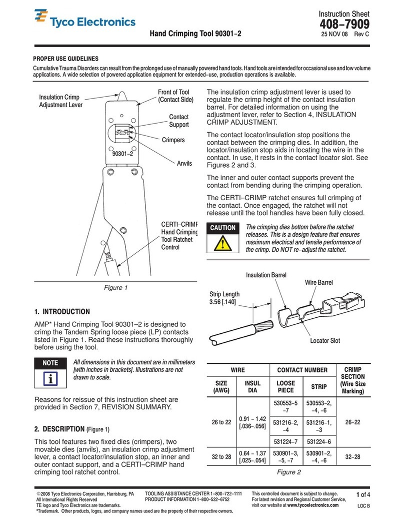
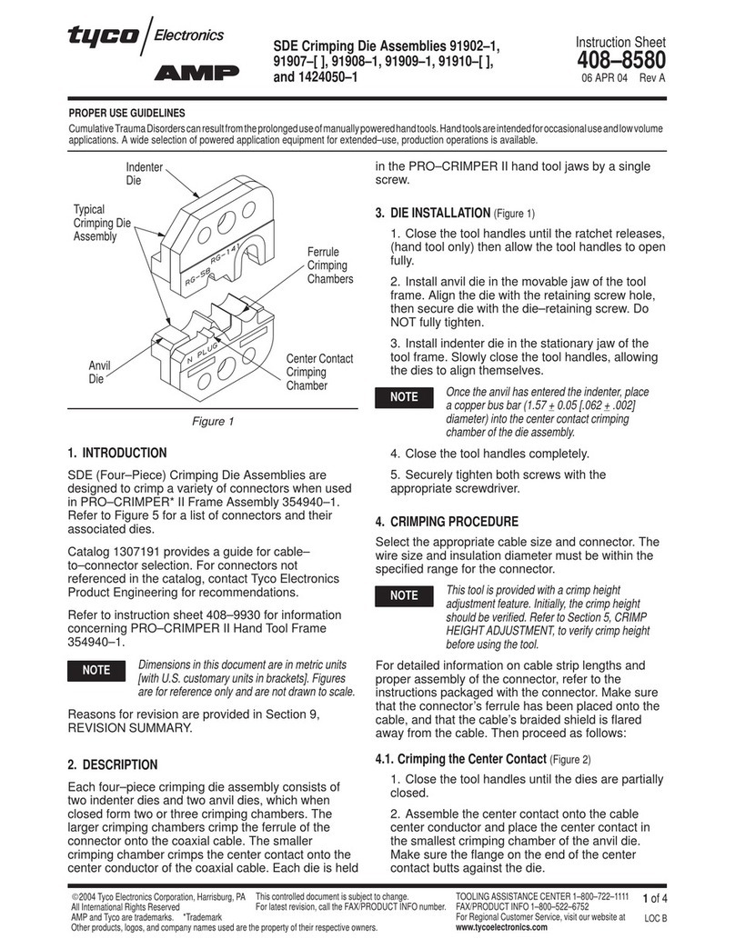
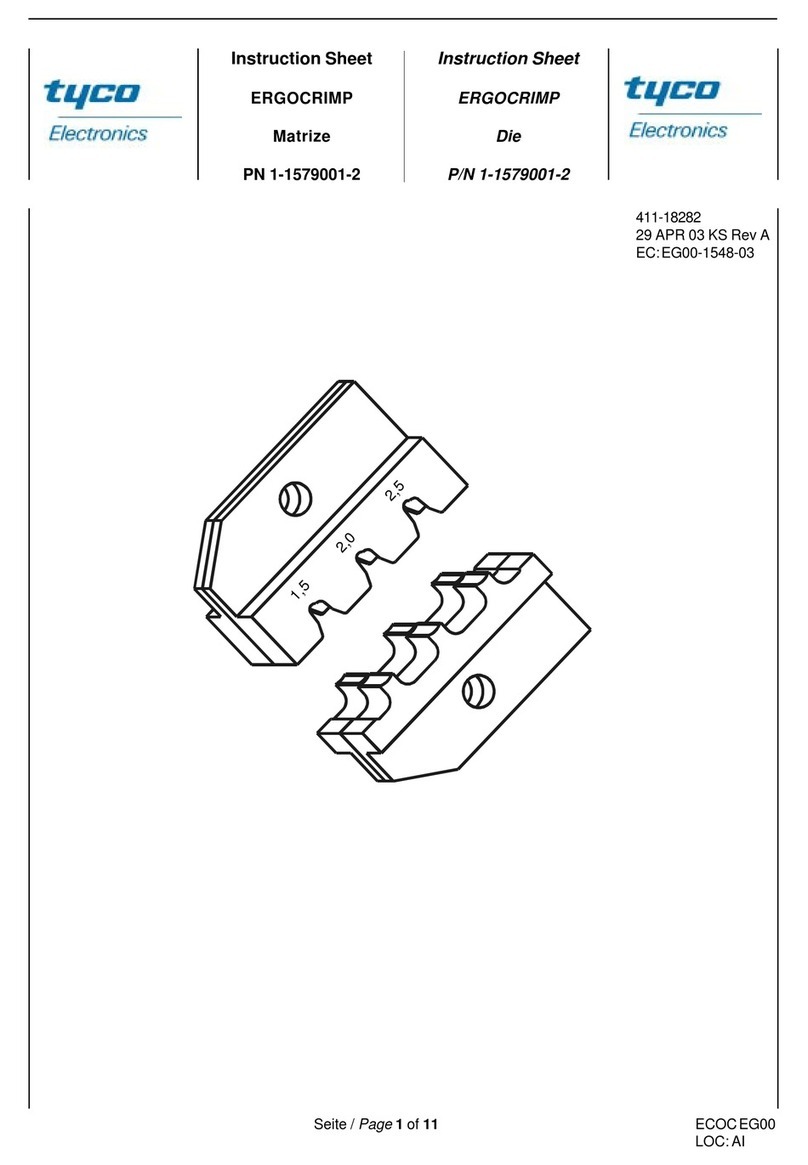
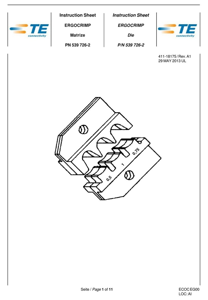
This IS describes the use and the operation of the
ERGOCRIMP Die P/N 6-1579001-5 for the ERGO-
CRIMP basis hand tool P/N 539 635-1 as well as
necessarymaintenancemeasures.
Forfurtherinformation,notincludedinthisIS,andfor
technical assistance please contact:
TycoElectronicsGmbH
Abtlg.Kundendienst
AMPèrestraße12-14
64625Bensheim
Matrize
411-18306RevA Die
411-18306RevA
Seite / Page 3 of 11
Matrizensatz Kontakt Größe (mm²) Leitung Abisolierlänge
PN PN Isol. ø (mm) (mm)
Dieassembly Contact Size (mm²) Wire Strip Lenght
Part number Partnumber Insul dia (mm) (mm)
6,8
3,2 - 3,6
3,8 - 4,2
4,0
6,0
6-1579001-5 963762/1452736
Bild / Illustration 1
2 Verwendungszweck
Mit dieser AMP ERGOCRIMP Matrize können fol-
gendeAMP-Crimpkontakteverarbeitetwerden:
Kontakttyp: PN:
LockingTabRecept.8.1 963762
Butt Splice Kontakt 1452736
HINWEIS
DieERGOCRIMPCrimp-Handzangeistfürdie
AufnahmeverschiedenerCrimpmatrizenaus-
gelegt. Kontaktieren Sie den AMP-Kunden-
dienst bezüglich der Verfügbarkeit von
CrimpmatrizenfürspezielleAnwendungen.
HINWEIS
Alle Abmessungen in dieser Betriebsanlei-
tungwerdeninMillimeter'mm'angegeben.Die
abgebildeten Komponenten sind nicht maß-
stabsgetreudargestellt.
HINWEISZURANWENDUNG
Kumulative traumatische Beschwerden kön-
nen die Folge einer dauerhaften Anwendung
vonHandzangensein.AMPHandzangensind
für gelegentliche Anwendungen und geringe
Stückzahlenvorgesehen.Fürdengesteiger-
tenBedarfbzw.fürdieProduktionbietetAMP
eine große Auswahl entsprechender Werk-
zeuge.
HINWEIS
Die Werkzeuge sind ausschließlich für den
hierbeschriebenenZweckzuverwenden!
2 Application
ThisAMPERGOCRIMPDie is suitable to crimp the
following AMP crimp contacts:
ContactType: P/N:
Locking Tab Recept. 8.1 963762
Butt Splice Contact 1452736
NOTE
The ERGOCRIMP Hand Tool has been
designed to accomodate different crimp die
sets. For availability of die sets for special
applications please contact the AMP Field
Service.
NOTE
Dimensions on this sheet are in millimeters
"mm".Illustrations and illustrations are not
drawntoscale.
PROPERUSEGUIDELINES
CumulativeTraumeDisorderscanresultfrom
a prolonged use of manually powered hand
tools. AMP hand tools are intended for
occasional use and low volume applications.
For extended use or production operations,
AMP offers a wide selection of powered
applicationequipment.
NOTE
The tool may only be used for the described
purpose.
Matrize
411-18306RevA Die
411-18306RevA
Seite / Page 4 of 11
3 Matrizen, Ein- und Ausbau 3 Die Installation and removal
Bild / Illustration 2
Matrizen - Einbau
1. ÖffnenSiedieZangengriffeundentfernenSiedie
beiden Befestigungsschrauben aus den Crimp-
backen.
2. Positionieren Sie die Crimper-Matrize für Draht-
undIsolationscrimpinderfeststehendenCrimp-
backe, so daß die Abschrägungen nach außen
zeigen.
3. DrehenSieeineMatrizen-Befestigungsschraube
(M4x11) durch Backe und Matrize, ziehen Sie
aber die Schraube noch nicht fest.
4. PositionierenSiedieuntereMatrizeinderbeweg-
lichen Crimpbacke der Handzange. Drehen Sie
eine Matrizen-Befestigungsschraube (M4x20)
durchBackeundMatrize,ziehenSiedieSchrau-
be aber noch nicht fest.
HINWEIS
Der Ratschenmechanismus der Handzange
besitzt Raststufen, die beim Schließen der
Zangengriffesiebenhörbare'Klicks'ergeben.
Beimsechsten (6.) 'Klick' wird derRatschen-
mechanismusausgelöst(geöffnet).
Die - Installation
1. Open the tool handles and remove the two die
retainingscrewsfromthe tool jaws.
2.Move the wire and insulation crimper dies, with
the chamfers facing the front of the stationary
jaws.
3. Insertadieretentionscrew (M4x11)throughthe
jaw and die and tighten the screw so that the die
is held in place, but do not tighten the screw
completelyat this point.
4. Place the lower die in the moving jaw of the tool
frame. Install a die retention screw (M4x20)
throughthe jawanddieandtightenthescrewso
thatthedieisheldinplace,butdonottightenthe
screw completely at this point.
NOTE
The ERGOCRIMP tool ratchet has detents
that are audible as seven "clicks" as the
handles are closed. The ratchet releases on
the sixth "click".
Zangenrückseite
Back of Tool
Matrizen-
befestigungs-
schrauben
Die
retaining
screws
FeststehendeCrimpbacke
Stationaryjaws
RatschenNot-Entriegelung
Emergencyadjustmentwheel
Abschrägung
Chamfer
UntereMatrize
Lowerdie
ObereMatrize
Upperdie
Kontaktabstützung
Contactguide
Sechskantmutter
Nut
Matrize
411-18306RevA Die
411-18306RevA
Seite / Page 5 of 11
5. Drücken Sie die Zangengriffe langsam zusam-
men,sodaß dieMatrizenaneinandergefügt und
ausgerichtet werden. Drücken Sie die Zangen-
griffe bis zum fünften (5.) 'Klick' zusammen und
ziehen Sie dann die beiden Matrizen-Be-
festigungsschraubenfest.
6. Befestigen Sie den Kontakabstützung auf der
beweglichenCrimpbackeindemSiedieentspre-
chendeSechskantmutterM4DIN934festziehen.
7. PrüfenSiedieCrimphöhen.
Justieren Sie wenn nötig wie unter Kap. 6 be-
schrieben.
Matrizen - Ausbau
Für den Ausbau des Matrizensatzes schließen
Sie die Zange bis der Ratschenmechanismus
auslöstunddieZangengriffe(ganz)öffnen.Lösen
und entfernen Sie die Sechskantmutter und die
beiden Matrizen-Befestigungsschrauben und
schiebenSiedieMatrizenausdenCrimpbacken.
4 Crimpverfahren
HINWEIS
Die Crimp-Handzange bietet eine Einstell-
möglichkeit der Crimphöhe. Die Crimphöhe
muß zu Anfang, wie nachfolgend spezifiziert
(Tabelle)undbeschrieben,überprüftwerden,
bevor gewünschte Kontakte und Leitungs-
größenverarbeitetwerden.
WählenSieeineLeitungmitspezifizierterGrößeund
Isolationsdurchmesser (Bild 1). Entfernen Sie die
IsolationumdieangegebeneLängeohnedieDraht-
litzenzuverbiegenoderzubeschädigen.WählenSie
einen passenden Kontakt, und bestimmen Sie die
korrekteKontaktaufnahmeentsprechendderMarkie-
rungen(Leitungsgröße)aufderZange.VerfahrenSie
nunwiefolgt:
1. HaltenSiedieCrimpzangeso,daßdieRückseite
derZange(Leitungsseite)zuIhnenzeigt.Drücken
Sie die Zangengriffe zusammen und lassen Sie
dieZangevollständigöffnen.
2. HaltenSiedenKontaktimKontaktierbereichfest
undschiebenSieihnvonderZangenvorderseite
mitderIsolationscrimphülsevoranindieZange.
5. Slowlyclosethetoolhandles,allowingthediesto
mateand/oralign.Continueclosingthetoolhandles
until the rachet makes the fifth "click," then
tighten both die retention screws until snug.
6. Installthelocatorassemblyonthestationaryjaw
andtightenthehexnut (M4 DIN 934).
7. Check the crimp heights. If necessary adjust
them as described in Chap. 6.
Die - removal
To remove the die assembly, close the tool
handles until the ratchet releases, and allow the
handlestoopenfully.Loosenandremovethedie
retentionscrewsandslidethediesoutofthetool
jaws.
4 Crimpingprocedure
NOTE
This tool is provided with a crimp adjustment
feature. Initially, the crimp height should be
verified as specified in Illustration 4. Refer to
Section 5, CRIMP HEIGHT INSPECTION,
and Section 6, CRIMP HEIGHT ADJUST-
MENT,to verifycrimpheightbeforeusingthe
tooltocrimpdesiredcontactsandwiresizes.
RefertothetableinIllustration1andselectwireofthe
specifiedsizeandinsulationdiameter. Stripthewire
tothelengthindicatedinIllustration1,takingcarenot
tobendortodamagethewirestrands.Chooseafitting
contact and identify the appropriate crimp section
accordingtothewiresizemarkingonthetool. Refer
to Illustration 2 and proceed as follows:
1. Holdthetoolsothattheback(wireside)isfacing
you. Squeeze tool handles together and allow
them to open fully.
2. Holdingthecontactbythe matingend,insert the
contact- insulation barrel first - throughthe front
ofthetooland intotheappropriatecrimpsection.
Matrize
411-18306RevA Die
411-18306RevA
Seite / Page 6 of 11
Zangenvorderseite
Front of Tool Zangenrückseite
Back of Tool
Abisolierlänge
Striplenght
Kontakt (typ.)
Contact(Typ)
Positionierungin
Drahtanschlag-
Schlitz
Locator in Wire stop slot
Leitungbis aufAnschlag
eingeführt
Wire inserted to stop
Bild / Illustration 3
6. Halten Sie die Leitung in dieser Stellung und
drückenSiedieZangengriffezusammen,bisder
Ratschenmechanismusauslöstbzw.öffnet.Las-
senSiedieZangevollständigöffnenundentneh-
men Sie den gecrimpten Kontakt.
7. ÜberprüfenSiedieCrimphöhe,wienachstehend
beschrieben. Nehmen Sie ggf. eine Einstellung
derCrimphöhevor.
6. Holding the wire in place, squeeze tool handles
togetheruntilratchetreleases.Allowtoolhandles
toopenandremovecrimpedcontact.
7. Check the contacts crimp height as described in
Section 5, CRIMP HEIGHT INSPECTION. If
necessary, adjust the crimp height as described
inSection6,CRIMP HEIGHT ADJUSTMENT.
3. Holdingthecontactbythe matingend,insert the
3. Positionthe contactsothatthemating end of
thecontactisonthecontactguidesideofthetool,
and that the open "U" of the wire and insulation
barrels face the top of the tool.
CAUTION
Make sure that both crimpflanks of the
insulation barrel are started evenly into the
crimpingsection.DoNOTattempttocrimpan
improperlypositionedcontact.
4. Holdthecontactinpositionandsqueezethetool
handlestogetheruntilratchetengagessufficiently
to hold the contact in position. Do NOT deform
insulationbarrelorwirebarrel.
5. Insert stripped wire into contact wire barrel
(Figure3).
3. Positionieren Sie den Kontakt so, daß sich der
KontaktierbereichdesKontaktesaufderSeiteder
KontaktabstützungbefindetunddieCrimpflanken
(U-Form) des Draht- und Isolationscrimps nach
obengerichtetsind.
VORSICHT
Stellen Sie sicher, daß die beiden Crimp-
flankendesIsolationscrimpsimCrimpbereich
gleichmäßig geführt werden. Versuchen Sie
NICHT,einenungenaupositioniertenKontakt
zu crimpen.
4. Halten Sie den Kontakt in Position und drücken
Sie die Zangengriffe soweit zusammen, bis der
Ratschenmechanismusentsprechendverriegelt
und der Kontakt in der Zange gehalten wird.
Achten Sie darauf, daß Sie die Isolations- und
DrahtcrimpflankenNICHTdeformieren.
5. Führen Sie die abisolierte Leitung in die
Drahtcrimphülse(Bild3).
Matrize
411-18306RevA Die
411-18306RevA
Seite / Page 7 of 11
Die Spitze muß mittig
aufderDrahtcrimphülse
gegenüberderCrimpnaht
positioniertwerden
ModifizierterAmboß
Modifiedanvil
5 Crimpheightinspection
Thisinspectionrequirestheuseofamicrometerwith
a modified anvil. AMP recommends the modified
micrometerAMP-P/N:675836-0.
Proceedasfollows:
1. Refer toIllustration4andselectawire(maximum
size) for each crimp section listed.
2. Refer to Section 4, CRIMPING PROCEDURE,
andcrimpthecontact(s)accordingly.
3. Using a crimp height comparator, measure the
wirebarrelcrimpheightasshowninIllustration4.
If the crimp height conforms to that shown in the
table,thetoolisconsidereddimensionallycorrect.
Ifnot,thetoolmustbeadjusted.RefertoSection
6,CRIMPHEIGHTADJUSTMENT.
Bild / Illustration 4
Position point on center of
wirebarreloppositeseam
4,0 mm² 4,0mm² 2,20mm 4,2mm
6,0mm² 6,0mm² 2,58mm 4,7mm
5 Überprüfung der Crimphöhe
ZurÜberprüfungbzw.MessungderCrimphöheistein
Mikrometer mit modifiziertem Amboß erforderlich
AMP-PN:675836-0
VerfahrenSiewiefolgt:
1. WählenSieausderTabelle(Bild4) jeeineLeitung
(mitmax.Größe)fürdiegelistetenCrimp-Größen-
bereiche.
2. Crimpen Sie einen oder mehrere Kontakte wie
zuvorbeschrieben.
3. Messen Sie mit dem Mikrometer die Crimphöhe
derDrahtcrimphülsewieinderAbbildung(Bild4)
gezeigt. Entspricht die gemessene Crimphöhe
denAngabeninderTabelle,soistdieCrimpzange
korrekt justiert. Anderenfalls ist eine Einstellung
derCrimphöhevorzunehmen.
<
<
"B"
Leitungsgröße
(Max.)
Wire size
(max.)
Crimpbereich
(Drahtgr.ber.markg.
Crimpsection
(Wire size marking)
Crimphöhe(A)
u. Toleranz (+/- 0,05)
Crimp height dim. (A)
andtolerance(+/-0.05)
Crimphöhe(B)
u. Toleranz (+/- 0,2)
Crimp height dim. (B)
andtolerance(+/-0.2)
Matrize
411-18306RevA Die
411-18306RevA
Seite / Page 8 of 11
Bild / Illustration 5
Schaftschraube
screwedstoppin
Einstellrad
adjustmentwheel
Sicherungsscheibe
retainingplate
6 Crimpheightadjustment
The tool frame assembly features a ratchet
mechanism and adjustment wheel with a range of
settings. The ratchet mechanism ensures that the
toolhascompletedthecycle.Theadjustmentwheel
controls the operating distance of the tool jaws
(before the ratchet opens) thereby controlling the
required crimp force. Although the ratchet is preset
prior to shipment, it is important that you verify the
crimpheight.Also,generaluseandsubsequentwear
may cause the tool to go out of adjustment. It is
recommended that the crimp height be inspected -
and adjusted, if necessary - on a regular basis by
qualitycontrolpersonnel.
1. Crimpacontactontoaproperly-preparedwireof
the correct size.
2. Ifthecrimpheightisgreaterthanrecommended,
open the plier and remove the screwed stop pin
withascrewdriver.Rotatetheadjustmentwheel
COUNTERCLOCKWISE(+).Ifa looser crimpis
required, rotate the adjustment wheel CLOCK-
WISE (-) (Illustration 5).
3. Replacethescrewedstoppin(Illustration5).
4. Make a sample crimp and measure the crimp
height. If the dimension is acceptable, replace
andsecurethescrewedstoppin.Ifthedimension
is unacceptable, continue to adjust the ratchet,
and again measure a sample crimp.
6 Einstellung der Crimphöhe
Die Crimp-Handzange besitzt einen Ratschen-
mechanismus mit einem Einstellrad, das einen be-
stimmten Einstellbereich aufweist. Durch den
Ratschenmechanismuswirdsichergestellt,daßder
Crimpzyklusvollständigbeendetwird.ÜberdasEin-
stellrad wird der Betätigungsweg (vor Öffnen der
Ratsche)unddamitdieerforderlicheCrimpkraftein-
gestellt. Auch trotz Voreinstellung ab Werk ist es
sehrwichtig,dieCrimphöhezuüberprüfen.Üblicher
GebrauchundAbnutzungsindebenfallsUrsachefür
eineFehleinstellungderCrimphöhe.Eswirdempfoh-
len,daßdieCrimphöheregelmäßigdurchQualitäts-
Kontroll-Personalüberprüftundggf.eingestelltwird.
1. CrimpenSieeinenKontakt an eine ordnungsge-
mäß vorbereitete (abisolierte) Leitung korrekter
Größe(Querschnitt).
2. IstdieCrimphöhegrößeralsempfohlen,öffnenSie
dieZangeundentfernen miteinemSchraubendre-
her die Schaftschraube. Drehen Sie das Ein-
stellradGEGENdenUhrzeigersinn(+).
IsteinegrößereCrimphöheerforderlich,sodrehen
Sie das Einstellrad IM Uhrzeigersinn, um einen
'niederen'Werteinzustellen(-)
3. SichernSiedasEinstellradmitderSchaftschrau-
be (Bild 5).
4. Crimpen Sie einen Kontakt und messen Sie die
Crimphöhe. Ist die Crimphöhe nicht akzeptabel,
sowiederholenSiedieEinstellung.
Matrize
411-18306RevA Die
411-18306RevA
Seite / Page 9 of 11
7 Wartung, Instandhaltung
7.1 Tägliche Wartung
ZurtäglichenWartungsind folgendeSchrittedurch-
zuführen:
1. EntfernenSievomWerkzeugStaub,Feuchtigkeit
undandereRückständemiteinersauberen,wei-
chen Bürste oder einem fusselfreien Tuch. Ver-
wenden Sie keine harten oder abschleifenden
Mittel,mitdenendasWerkzeugbeschädigtwer-
denkönnte.
2. Stellen Sie sicher, daß der Lagerbolzen einge-
setztunddurchdieSicherungsscheibegehalten
wird und die Schaftschraube zur Sicherung des
Einstellrades fest ist.
3. VersehenSiealle Stifte, Drehpunkte und Lager-
oberflächenmiteinemdünnenÖlfilmeinesguten
SAE 20Motoröls.ÖlenSieabernichtübermäßig.
4. WirddieHandzange nicht benötigt, dann schlie-
ßen Sie die Zangengriffe und lagern die Zange
sauberundtrocken.
7.2 Periodische Überprüfung
EineÜberprüfungderCrimpzangesolltedurchquali-
fiziertesPersonalregelmäßig(jenachNutzung)durch-
geführtundaufgezeichnetwerden.
1. Entfernen Sie jegliche Schmiermittel und Rück-
stände,indemSiedieHandzange(Griffeteilweise
geschlossen) in ein Fett-Lösemittel eintauchen,
dasFarbeund Kunststoffenichtangreift.
2. Stellen Sie sicher, daß alle Lagerbolzen einge-
setzt und durch Sicherungsscheiben gehalten
werden.
3. SchließenSiedieZangengriffebisderRatschen-
mechanismusauslöstbzw.öffnet,undlassenSie
dieZangengriffefreiöffnen.ÖffnendieGriffenicht
schnell und vollständig, dann ist die Feder be-
schädigt und muß ersetzt werden.
4. Überprüfen Sie die Zange auf Abnutzung und
Beschädigung, insbesondere im Bereich der
CrimpbackenundDrehzapfen.
7 Maintenance / Inspection
7.1 Daily Maintenance
AMPrecommendsthatoperatorsofthetoolbemade
awareofthefollowingstepsofdailymaintenance:
1. Remove dust, moisture, and any other
contaminants from the tool with a clean, soft
brush,oraclean,soft,lint-freecloth.DoNOTuse
hard or abrasive objects that could damage the
tool.
2. Make certain that the pivot pins are in place and
thattheyaresecuredwithretainingplateandthat
locking screw of the adjustment wheel is tight.
3. Allpins,pivotpoints,andbearingsurfacesshould
beprotectedwithathincoatofanygoodSAENo.
20 motor oil. Do not oil excessively.
4. Whenthetool is not in use, keep handles closed
to prevent objects from becoming lodged in the
crimpingjaws.Storethetoolinaclean,dryarea.
7.2 PeriodicInspection
Regularinspectionsofthetoolshouldbeperformed
by quality control personnel. A record of scheduled
inspectionsshouldremainwiththetoolorbesupplied
tosupervisorypersonnel responsible forthetool.
Inspectionfrequencyshouldbebaseduponamount
of usage, working conditions, operator training and
skill and established company standards.
1. Remove all lubrication and accumulated film by
immersingthe tool(handlespartiallyclosed)ina
suitablecommercialdegreaserthatwillnotaffect
paint or plastic material.
2. Make certain that all pivot pins are in place and
securedwithretainingplates.
3. Closetoolhandlesuntilratchetreleasesandthen
allow them to open freely. If they do not open
quicklyandfully,thespringisdefectiveandmust
bereplaced.
4. Inspectthetoolframeforwearordamage,paying
particular attention to the tool jaws and pivot
points.
Matrize
411-18306RevA Die
411-18306RevA
Seite / Page 10 of 11
5. Crimpthecontactsandmeasureyouthecrimping
height.Testcriteriumforacorrectfunctionofthe
hand tools are the crimping height specification
from the table (Illustration 4)
Part list of the single parts
without dies
5. Crimpen Sie die Kontakte und messen Sie
dieCrimphöhe.
PrüfkriteriumfüreinerichtigeFunktionderHand-
zangesinddieCrimphöhenangabenausder
Tabelle(Bild4)
Stückliste der Einzelteile
ohne Matrize
Position Best.Nr. Beschreibung Menge
Item PartNo. Description Quantity
1 2-1579015-0 Kontaktabstützung 1
Contactguide
2 1-0519151-2 SchraubeM4x20 1
ScrewM4x20
3 8-0539634-5 SchraubeM4x11 1
ScrewM4x11
4 0-0519021-8 MutterM4DIN934 1
NutM4DIN934
5 1-0744011-3 InstructionSheet 1
411-18306
Seite / Page 11 of 11
Americas
Argentina - Buenos Aires
Phone: +54-1-733-2000
Fax: +54-1-717-0988
Brazil - Sao Paulo
Phone: +55-11-3611-1311
Fax: +55-11-3611-0397
Canada - Toronto
Phone: +905-475-6222
Fax: +905-474-5520
Chile -Santiago
Phone: +56-2-739-1230
Fax: +56-2-739-1227
Colombia - Bogota
Phone: +57-1-231-9398
Fax: +57-1-240-3769
Mexico - Mexico City
Phone: +52-5-729-0400
Fax: +52-5-361-8545
United States - Harrisburg,
PA
Phone: +717-564-0100
Fax: +717-986-7575
Venezuela - Caracas
Phone: +58-2-986-7774
Fax: +58-2-986-9739
For Latin/South American
Countries not shown
Phone: +54-11-4733-2015
Fax: +54-11-4733-2083
Asia/Pacific
Australia - Sydney
Phone: +61-2-9840-8200
Fax: +61-2-9899-5649
India -Bangalore
Phone: +91-80-841-0200
Fax: +91-80-841-0210
Indonesia - Jakarta
Phone: +6221-526-7852
Fax: +6221-526-7856
Japan - Kawasaki, Kanagawa
Phone: +81-44-844-8079
Fax: +81-44-844-8733
Korea - Seoul
Phone: +82-2-3274-0535
Fax: +82-2-3274-0524/0531
Malaysia - Selangor
Phone: +60-3-7053055
Fax: +60-3-7053066
New Zealand - Auckland
Phone: +64-9-634-4580
Fax: +64-9-634-4586
Philippines - Makati City
Phone: +632-867-8641
Fax: +632-867-8661
People’s Republic of China
Hong Kong
Phone: +852-2735-1628
Fax: +852-2735-0243
Shanghai
Phone: +86-21-6485-0602
Fax: +86-21-6485-0728
Shunde
Phone: +86-765-775-1368
Fax: +86-765-775-2823
Singapore - Singapore
Phone: +65-482-0311
Fax: +65-482-1012
Taiwan - Taipei
Phone: +886-2-2664-9977
Fax: +886-2-2664-9900
Thailand - Bangkok
Phone: +66-2-955-0500
Fax: +66-2-955-0505
Vietnam - Ho Chi Minh City
Phone: +84-8-8232-546/7
Fax: +84-8-8221-443
Europe/Middle East/Africa
Austria - Vienna
Phone: +43-190-560-0
Fax: +43-190-560-1333
Belgium - Kessel-Lo
Phone: +32-16-352-300
Fax: +32-16-352-352
Bulgaria - Sofia
Phone: +359-2-971-2152
Fax: +359-2-971-2153
Czech Republic - Kurim
Phone: +420-5-41-162-111
Fax: +420-5-41-162-223
Denmark - Viby J
Phone: +45-70-15-52-00
Fax: +45-86-29-51-33
Egypt - Cairo
Phone: +20-2-417-76-47
Fax: +20-2-419-23-34
Estonia - Tallinn
Phone: +372-65-05-474
Fax: +372-65-05-470
Finland - Helsinki
Phone: +358-95-12-34-20
Fax: +358-95-12-34-250
France -
Cergy-Pontoise-Cedex
Phone: +33-1-3420-8888
Fax: +33-1-3420-8600
France
AMP Electronics-Export-
St Ouen L'Aumone
Phone: +33-1-3440-7200
Fax: +33-1-3440-7220 or
+33-1-3440-7230
Great Britain -
Stanmore Middlesex
Phone: +44-181-954-2356
Fax: +44-181-954-6234
Greece - Athens
Phone: +30-1-9370-396/397
Fax: +30-1-9370-655
Germany - Bensheim
Phone: +49-6251-133-0
Fax: +49-6251-133-1600
Germany - Langen
Phone: +49-6103-709-0
Fax: +49-6103-709-1223
Germany - Speyer
Phone: +49-6232-30-0
Fax: +49-6232-30-2243
Germany
HTS Division - Neunkirchen
Phone: +49-2247-305-0
Fax: +49-2247-305-122
Hungary - Budapest
Phone: +36-1-289-1000
Fax: +36-1-289-1010
Ireland - Dublin
Phone: +353-1-820-3000
Fax: +353-1-820-9790
Israel - Yokneam
Phone: +972-4-959-0508
Fax: +972-4-959-0506
Italy - Collegno (Torino)
Phone: +39-011-4012-111
Fax: +39-011-4031-116
Lithuania - Vilnius
Phone: +370-2-2314-02
Fax: +370-2-2314-03
Netherlands -
’s-Hertogenbosch
Phone: +31-73-6246-246
Fax: +31-73-6212-365
Norway - Nesbru
Phone: +47-66-77-88-99
Fax: +47-66-77-88-55
Poland - Warsaw
Phone: +48-22-5490-888
Fax: +48-22-5490-880
Romania - Bucharest
Phone: +40-1-311-3479 + 3596
Fax: +40-1-312-0574
Russia - Moscow
Phone: +7-095-926-55-06...09
Fax: +7-095-926-55-05
Russia - St. Petersburg
Phone: +7-812-325-30-83
Fax: +7-812-325-32-88
Slovakia - Banska Bystrica
Phone: +421-48-415-20-11/12
Fax: +421-48-415-20-13
Slovenia - Ljubljana
Phone: +386-1561-3270
Fax: +386-1561-3240
South Africa - Port Elizabeth
Phone: +27-41-405-4500
Fax: +27-41-486-1314
Spain - Barcelona
Phone: +34-93-291-0330
Fax: +34-93-201-7879
Sweden - Upplands Väsby
Phone: +46-8-50-72-50-00
Fax: +46-8-50-72-50-01
Switzerland - Steinach
Phone: +41-71-447-0447
Fax: +41-71-447-0444
Turkey - Istanbul
Phone: +90-212-281-8181...3
+90-212-282-5130/5430
Fax: +90-212-281-8184
Ukraine - Kiev
Phone: +38-044-238-6908
Fax: +38-044-568-5740
Worldwide Companies
http://www.tycoelectronics.com 09-01 GATD

Other Tyco Electronics Crimping Tools manuals
Tyco Electronics 1-1579001-2 User manual

Tyco Electronics

Tyco Electronics 1-1579001-2 User manual

Tyco Electronics PRO-CRIMPER III User manual
Tyco Electronics

Tyco Electronics PRO-CRIMPER III User manual

Tyco Electronics SDE PEW-12 User manual

Tyco Electronics

Tyco Electronics SDE PEW-12 User manual

Tyco Electronics SIMEL Autocoup CC040 Cof. + charg. User manual

Tyco Electronics

Tyco Electronics SIMEL Autocoup CC040 Cof. + charg. User manual

Tyco Electronics SOLARLOK 1579004-9 User manual

Tyco Electronics

Tyco Electronics SOLARLOK 1579004-9 User manual

Tyco Electronics 3-1579002-1 User manual

Tyco Electronics

Tyco Electronics 3-1579002-1 User manual

Tyco Electronics 58569-1 User manual

Tyco Electronics

Tyco Electronics 58569-1 User manual

Tyco Electronics 58593-1 User manual

Tyco Electronics

Tyco Electronics 58593-1 User manual

Tyco Electronics 90015 User manual

Tyco Electronics

Tyco Electronics 90015 User manual

Tyco Electronics PRO-CRIMPER III User manual

Tyco Electronics

Tyco Electronics PRO-CRIMPER III User manual

Tyco Electronics PRO-CRIMPER III User manual

Tyco Electronics

Tyco Electronics PRO-CRIMPER III User manual

Tyco Electronics 9-1478246-0 User manual

Tyco Electronics

Tyco Electronics 9-1478246-0 User manual

Tyco Electronics 2-1579004-9 User manual

Tyco Electronics

Tyco Electronics 2-1579004-9 User manual

Tyco Electronics ERGOCRIMP 2-1579021-9 User manual

Tyco Electronics

Tyco Electronics ERGOCRIMP 2-1579021-9 User manual

Tyco Electronics PRO- CRIMPER III User manual

Tyco Electronics

Tyco Electronics PRO- CRIMPER III User manual

Tyco Electronics 2-231652-1 User manual
Tyco Electronics

Tyco Electronics 2-231652-1 User manual

Tyco Electronics 0-0654174-1 User manual

Tyco Electronics

Tyco Electronics 0-0654174-1 User manual

Tyco Electronics 48858-1 User manual

Tyco Electronics

Tyco Electronics 48858-1 User manual

Tyco Electronics PRO-CRIMPER III User manual

Tyco Electronics

Tyco Electronics PRO-CRIMPER III User manual
Tyco Electronics PRO-CRIMPER III 58603-1 User manual

Tyco Electronics

Tyco Electronics PRO-CRIMPER III 58603-1 User manual

Tyco Electronics PRO CRIMPER III User manual

Tyco Electronics

Tyco Electronics PRO CRIMPER III User manual

Tyco Electronics 2063195-1 User manual

Tyco Electronics

Tyco Electronics 2063195-1 User manual

Tyco Electronics 58532 Series User manual

Tyco Electronics

Tyco Electronics 58532 Series User manual

Tyco Electronics PRO-CRIMPER III User manual
Tyco Electronics

Tyco Electronics PRO-CRIMPER III User manual

Popular Crimping Tools manuals by other brands

ODU 080.000.064.000.000 instruction manual

ODU

ODU 080.000.064.000.000 instruction manual

Emerson Klauke ES 20RMCCFB manual

Emerson

Emerson Klauke ES 20RMCCFB manual

Emerson Klauke ESG 105RMCCFM manual

Emerson

Emerson Klauke ESG 105RMCCFM manual

Glomar Dr. Peters EKS-3-PRO instruction manual

Glomar

Glomar Dr. Peters EKS-3-PRO instruction manual

UTILCO UR-U42 instruction manual

UTILCO

UTILCO UR-U42 instruction manual

Panduit CTFP-100 operating instructions

Panduit

Panduit CTFP-100 operating instructions

TE Connectivity 2395308-1 instruction sheet

TE Connectivity

TE Connectivity 2395308-1 instruction sheet

TE Connectivity CERTI-CRIMP II 2381707-1 instruction sheet

TE Connectivity

TE Connectivity CERTI-CRIMP II 2381707-1 instruction sheet

TE Connectivity AT-65 Operation manual

TE Connectivity

TE Connectivity AT-65 Operation manual

NovoPress ACO153 BT operating manual

NovoPress

NovoPress ACO153 BT operating manual

molex 207129 Series Specification sheet
molex

molex 207129 Series Specification sheet

Emerson Klauke UAP432CFB manual

Emerson

Emerson Klauke UAP432CFB manual

Fohrenbach RCY21208 user manual

Fohrenbach

Fohrenbach RCY21208 user manual

WEITKOWITZ APW30 instruction manual

WEITKOWITZ

WEITKOWITZ APW30 instruction manual

West Mountain Radio RIGrunner manual

West Mountain Radio

West Mountain Radio RIGrunner manual

Milwaukee M18 FORCE LOGIC 2978-20 Operator's manual

Milwaukee

Milwaukee M18 FORCE LOGIC 2978-20 Operator's manual

TE Connectivity 2063574-1 Assembly instructions

TE Connectivity

TE Connectivity 2063574-1 Assembly instructions

Panduit CT-1002 Operation and maintenance instruction manual

Panduit

Panduit CT-1002 Operation and maintenance instruction manual

manuals.online logo
manuals.online logoBrands
  • About & Mission
  • Contact us
  • Privacy Policy
  • Terms and Conditions

Copyright 2025 Manuals.Online. All Rights Reserved.