manuals.online logo
Brands
  1. Home
  2. •
  3. Brands
  4. •
  5. Tyco Electronics
  6. •
  7. Crimping Tools
  8. •
  9. Tyco Electronics PRO-CRIMPER III User manual

Tyco Electronics PRO-CRIMPER III User manual

Instruction Sheet
PRO-CRIMPER* III
Hand Tool Assembly 217212-1 408-4145
LOC B
1
of 4
E
2009 Tyco Electronics Corporation, Harrisburg, PA
All International Rights Reserved
TE logo and Tyco Electronics are trademarks.
*Trademark. Other products, logos, and company names used are the property of their respective owners.
TOOLI G ASSISTA CE CE TER 1-800-722-1111
PRODUCT I FORMATIO 1-800-522-6752 This controlled document is subject to change.
For latest revision and Regional Customer Service,
visit our website at
www.tycoelectronics.com
20 MAR 09 Rev D
with Die Assembly 217212-2
PROPER USE GUIDELINES
CumulativeTraumaDisorderscanresultfromtheprolongeduse ofmanuallypoweredhandtools.Handtoolsareintendedforoccasionaluseandlowvolume
applications. A wide selection of powered application equipment for extended-use, production operations is available.
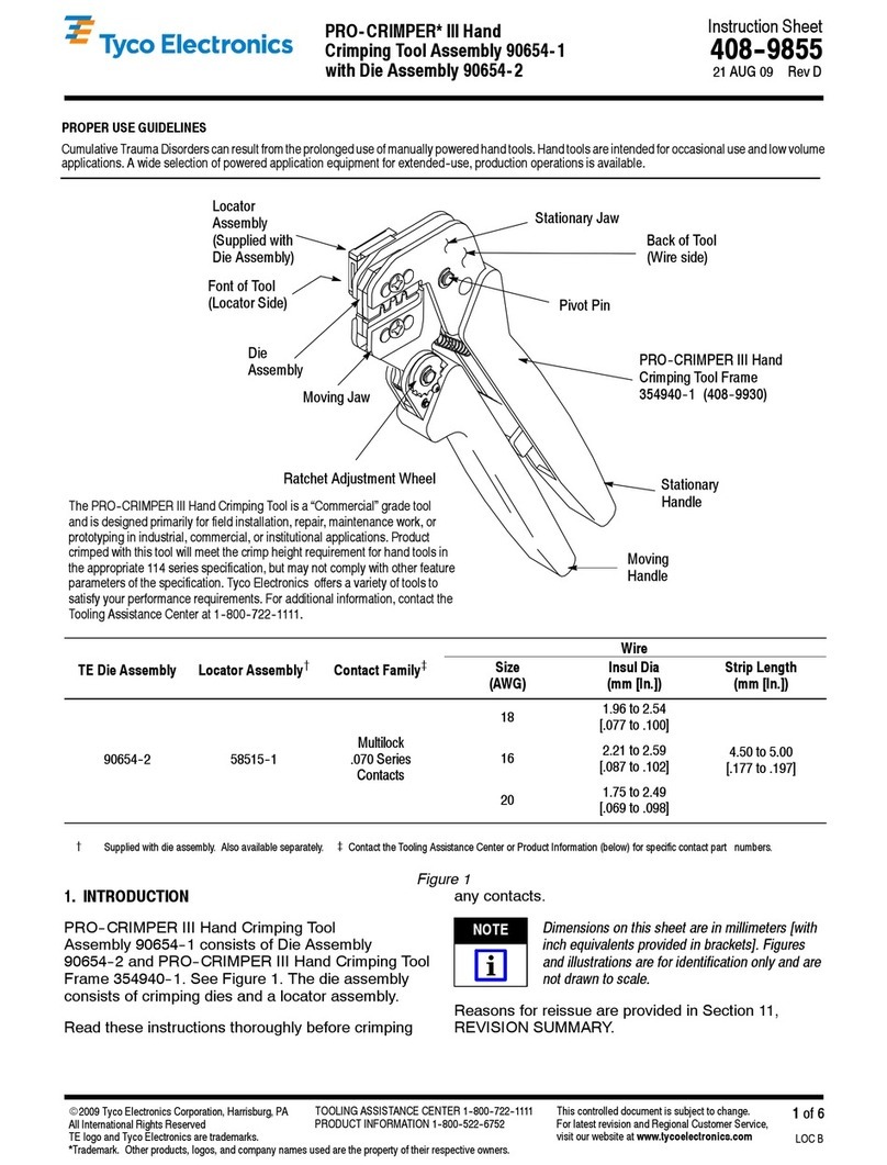
The PRO-CRIMPER III Hand Tool is a Commercial" grade tool and is
designed primarily for field installation, repair, maintenance work, or
prototyping in industrial, commercial, or institutional applications. Product
crimped with this tool will meet the crimp height requirement for hand tools in
the appropriate 114 Application Specification, but may not comply with other
feature parameters of the specification. Tyco Electronics offers a variety of
tools to satisfy your performance requirements. For additional information,
contact the Tooling Assistance Center at 1-800-722-1111.
CERTI-CRIMP*
Ratchet
PRO-CRIMPER III Hand Tool
Frame 354940-1
(See Instruction Sheet 408-9930)
Stationary
Handle
Moving
Handle
Back of Tool
(Wire Side)
Stationary
Jaw
Front of Tool
Die Assembly
217212-2
Moving
Jaw
DIE
ASSEMBL
CLOSED-END
SPLICE WIRE SOLID OR STRANDED
WIRE COMBINATION
CRIMPING
CHAMBER PART
NUMBER T PE SIZE RANGE
(AWG) CIRCULAR MIL
AREA RANGE STRIP LENGTH TABLE SHOWN ON
(INSTRUCTION SHEET)
Outer 35115 ECV
EC 22-14 509-5,180 8.76 +0.38 [.345 +.016] (408-1271)
Center 328730 ECV
EC 22-10 3,248-13,100 11.12 +0.38 [.438 +.016] (408-1003)
Inner 35653 EC 22-10 3,248-13,100 11.12 +0.38 [.438 +.016] (408-1021)
Figure 1
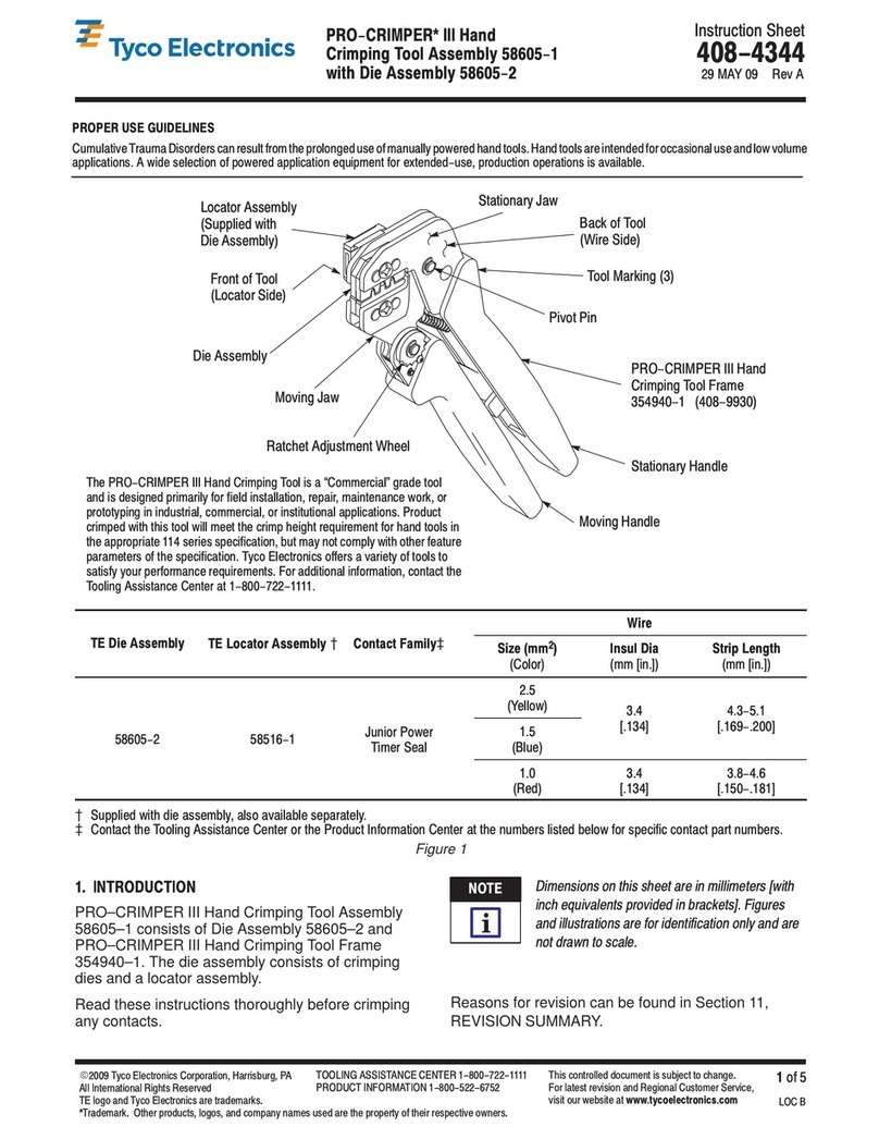
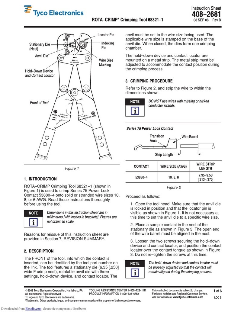
1. INTRODUCTION
PRO–CRIMPER III Hand Tool Assembly 217212–1
consists of Die Assembly 217212–2 and
PRO–CRIMPER III Hand Tool Frame 354940–1. The
die assembly consists of two crimping dies. Read
these instructions thoroughly before crimping any
splices.
Dimensions on this sheet are in millimeters [with
inch equivalents provided in brackets]. Figures
and illustrations are for identification only and are
not drawn to scale.
Reasons for reissue of this instruction sheet are
provided in Section 9, REVISION SUMMARY.
NOTE
i
408-4145
PRO-CRIMPER III H nd Tool Assembly 217212-1
Rev
D2
of 4 Tyco Elec ronics Corpora ion
Figure 2
Chamfer
Wire Crimper
Die
Wire Anvil
Die
Die Re aining
Screws
Die Re aining
Pins
Tool Frame
Chamfer
2. DESCRIPTION
(Figures 1 and 2)
The tool features a tool frame with a stationary jaw
and handle, a moving jaw, a moving handle, and a
CERTI–CRIMP ratchet that ensures full splice
crimping. The tool frame holds a die assembly with
three crimping chambers.
The die assembly features a wire anvil die and a wire
crimper die. Die retaining pins and die retaining
screws are used to position and secure the dies in the
tool frame.
3. INSTALLATION AND REMOVAL OF DIE ASSEMBLY
(Figure 2)
1. Open the tool handles and remove the two die
retaining screws from the tool jaws.
2. Place the wire anvil die so that the chamfered
side faces outward when mounted in the moving
jaw of the tool frame. Place the wire crimper die so
that the chamfered side faces outward when
mounted in the stationary jaw of the tool frame.
3. Insert two die retaining pins through each jaw
and into each die.
4. Insert the die retaining screws through each jaw
and into each die, and tighten the screws just
enough to hold the dies in place. Do
not
tighten the
screws completely at this time.
5. Carefully close the tool handles, making sure
that the anvil and crimper dies align properly.
Continue closing the tool handles until the ratchet
in the tool frame has engaged sufficiently to hold
the dies in place, then tighten both die retaining
screws.
6. To disassemble, close the tool handles until the
ratchet releases, remove the two die retaining
screws and the four die retaining pins, and slide
the dies out of the tool jaws.
4. CRIMPING PROCEDURE
Initially, the crimping chambers and t l ratchet
sh uld be inspected as specified in Secti n 5,
CRIMP ADJUSTMENT, t verify reliability bef re
using the t l t crimp desired splices and wire
sizes.
Refer to Figure 1 and select wire of the specified size.
Strip the wire to the length indicated in Figure 1,
taking care not to nick or cut wire strands. Select an
applicable splice and identify the appropriate crimping
chamber according to Figure 1. Refer to Figure 3 and
proceed as follows:
1. Squeeze tool handles together and allow them
to open fully.
2. Insert stripped wire into splice wire barrel until
the end of the conductor bottoms against the
splice.
3. Holding the wire, insert the splice—wire barrel
first—into the appropriate crimping chamber. Make
sure the wire barrel is centered in the crimping
chamber.
Make sure that b th sides f the wire barrel are
started evenly int the crimping chamber. D
NOT attempt t crimp an impr perly p siti ned
splice.
NOTE
i
CAUTION
!
408-4145
PRO-CRIMPER III Han Tool Assembly 217212-1
3
of 4Rev
D
Tyco Elec ronics Corpora ion
4. Holding the splice in place, squeeze tool
handles together until ratchet releases. Allow tool
handles to open and remove crimped splice.
5. Check the splice to ensure that the crimp is
centered on wire barrel and the stripped wires are
fully bottomed in the splice. Refer to Figure 3 for a
properly crimped splice.
Damaged product should not be used. If
damaged product is evident, it should be cut from
the wire and replaced with a new one.
5. CRIMP ADJUSTMENT
5.1. Gaging the Crimping Chamber
This inspection requires the use of a plug gage
conforming to the dimensions shown in Figure 4. Tyco
Electronics does not manufacture or market these
gages. To gage the crimping chamber, proceed as
follows:
1. Remove traces of oil or dirt from the crimping
chamber and plug gage.
2. Close the tool handles until it is evident that the
dies have bottomed; HOLD the tool in this position.
Do NOT force the dies beyond initial contact.
3. Align the GO element with the crimping
chamber. Push the element (without forcing it)
straight into the chamber. The GO element must
pass completely through the crimping chamber.
4. Align and try to insert the NO–GO element with
the same crimping chamber. The NO–GO element
may start entry but must not pass completely
through the crimping chamber.
If the crimping chamber conforms to the gage
inspection, the die assembly is considered
dimensionally correct and should be lubricated with a
THIN coat of any good grade SAE 20 motor oil. If not,
the dies or tool frame must be repaired before
returning it to service. See Section 8,
REPLACEMENT AND REPAIR.
For additional information concerning the use of a
plug gage, refer to Instruction Sheet 408–7424.
5.2. CERTI-CRIMP Ratchet
The CERTI–CRIMP ratchet should be checked to
make sure that the ratchet does not release
prematurely allowing the dies to open before they
have fully bottomed. Obtain a 0.025 [.001] shim that
is suitable for checking the clearance between the
bottoming surfaces of the crimping dies.
Proceed as follows:
1. Select a splice and the maximum number of
wires permitted as indicated in the splice wire
combination chart (refer to Figure 1).
2. Position the splice and wire between the
crimping dies, according to Section 4, CRIMPING
PROCEDURE. Holding the splice in place,
squeeze the tool handles together until the
CERTI–CRIMP ratchet releases. Hold the tool
handles in this position, maintaining just enough
pressure to keep the dies closed.
3. Check the clearance between the bottoming
surfaces of the crimping dies. If the clearance is
0.025 [.001] or less, the ratchet is satisfactory. If
clearance exceeds 0.025 [.001], the ratchet is out
of adjustment and must be repaired. See Section
8, REPLACEMENT AND REPAIR.
Figure 3
Back of Tool
Splice wi h
Wire Inser ed Crimp
Cen ered
S ripped Wires Fully
Bo omed in Splice
Note:
Crimp May Be Off Cen er Bu No
Off End of Wire Barrel
Ou er
Crimping
Chamber
Cen er
Crimping
Chamber
Inner
Crimping
Chamber
CAUTION
!
408-4145
PRO-CRIMPER III H nd Tool Assembly 217212-1
Rev
D4
of 4 Ty o Ele troni s Corporation
Crimping
Chamber
GO
Element NO-GO
Element
GO" gage must pass
ompletely through
rimping surfa e.
NO-GO" gage may enter
partially, but must not pass
ompletely through the length
of the rimping surfa e.
É
É
É
É
É
ÉÉ
ÉÉ
ÉÉ
ÉÉ
É
É
É
É
É
ÉÉ
ÉÉ
ÉÉ
ÉÉ
25.4 [1.00]
Min (Typ)
GO Dim. NO-GO Dim.
Suggested Plug Gage Design
Die Closure
Configuration
CRIMPING GAGE ELEMENT DIMENSIONS
CHAMBER GO NO-GO
Outer 2.438-2.443
[.0960-.0962] 2.540-2.545
[,1000-.1002]
Center 2.946-2.951
[.1160-.1162] 3.048-3.053
[.1200-.1202]
Inner 3.200-3.205
[.1260-.1262] 3.302-3.307
[.1300-.1302]
Figure 4
If the die assembly and tool conform to these
inspection procedures, lubricate it with a THIN coat of
any good SAE 20 motor oil and return it to service.
6. INSPECTION
The crimping dies should be inspected on a regular
basis to ensure that they have not become worn or
damaged. Inspect the crimping chambers for
flattened, chipped, worn, or broken areas. If damage
or abnormal wear is evident, the dies must be
replaced. See Section 8, REPLACEMENT AND
REPAIR.
7. MAINTENANCE
Ensure that the tool and dies are clean by wiping
them with a clean, soft cloth. Remove any debris with
a clean, soft brush. Do not use objects that could
damage the tool. When not in use, keep handles
closed to prevent objects from becoming lodged in
the crimping dies, and store in a clean, dry area.
8. REPLACEMENT AND REPAIR
Customer–replaceable parts are shown in Figure 1.
Available separately, PRO–CRIMPER III Repair Kit
679221–1 includes a variety of pins, rings, screws,
and springs. If the dies are damaged or worn
excessively, they must be replaced. Order the repair
kit and replaceable parts through your Tyco
Electronics Representative, or call 1–800–526–5142,
or send a facsimile of your purchase order to
717–986–7605, or write to:
CUSTOMER SERVICE (38–35)
TYCO ELECTRONICS CORPORATION
P.O. BOX 3608
HARRISBURG, PA 17105–3608
9. REVISION SUMMARY
Since the previous release, the Tyco Electronics’ logo
has been changed.

This manual suits for next models

2

Other Tyco Electronics Crimping Tools manuals
Tyco Electronics PRO-CRIMPER III User manual

Tyco Electronics

Tyco Electronics PRO-CRIMPER III User manual

Tyco Electronics 1490749-1 User manual

Tyco Electronics

Tyco Electronics 1490749-1 User manual

Tyco Electronics 58443-1 User manual

Tyco Electronics

Tyco Electronics 58443-1 User manual

Tyco Electronics PRO-CRIMPER III User manual

Tyco Electronics

Tyco Electronics PRO-CRIMPER III User manual

Tyco Electronics PRO-CRIMPER III User manual

Tyco Electronics

Tyco Electronics PRO-CRIMPER III User manual

Tyco Electronics 58569-1 User manual

Tyco Electronics

Tyco Electronics 58569-1 User manual

Tyco Electronics PRO-CRIMPER III User manual

Tyco Electronics

Tyco Electronics PRO-CRIMPER III User manual

Tyco Electronics 58593-1 User manual

Tyco Electronics

Tyco Electronics 58593-1 User manual

Tyco Electronics PRO- CRIMPER III User manual

Tyco Electronics

Tyco Electronics PRO- CRIMPER III User manual

Tyco Electronics 603995 Series User manual

Tyco Electronics

Tyco Electronics 603995 Series User manual

Tyco Electronics PRO-CRIMPER III User manual

Tyco Electronics

Tyco Electronics PRO-CRIMPER III User manual

Tyco Electronics PRO-CRIMPER III User manual

Tyco Electronics

Tyco Electronics PRO-CRIMPER III User manual

Tyco Electronics PRO-CRIMPER III User manual

Tyco Electronics

Tyco Electronics PRO-CRIMPER III User manual

Tyco Electronics 1490748-1 User manual

Tyco Electronics

Tyco Electronics 1490748-1 User manual

Tyco Electronics PRO-CRIMPER III User manual

Tyco Electronics

Tyco Electronics PRO-CRIMPER III User manual

Tyco Electronics 2063811-1 User manual

Tyco Electronics

Tyco Electronics 2063811-1 User manual

Tyco Electronics AUTOPRESS C120 Release Note

Tyco Electronics

Tyco Electronics AUTOPRESS C120 Release Note

Tyco Electronics AMP PRO–CRIMPER II User manual

Tyco Electronics

Tyco Electronics AMP PRO–CRIMPER II User manual

Tyco Electronics PRO-CRIMPER III User manual

Tyco Electronics

Tyco Electronics PRO-CRIMPER III User manual

Tyco Electronics PIDG STRATO-THERM 1-576778-0 User manual

Tyco Electronics

Tyco Electronics PIDG STRATO-THERM 1-576778-0 User manual

Tyco Electronics 2-1579004-9 User manual
Tyco Electronics

Tyco Electronics 2-1579004-9 User manual

Tyco Electronics PIDG STRATO-THERM User manual

Tyco Electronics

Tyco Electronics PIDG STRATO-THERM User manual

Tyco Electronics 90301-2 User manual

Tyco Electronics

Tyco Electronics 90301-2 User manual

Tyco Electronics AMP 91907 User manual

Tyco Electronics

Tyco Electronics AMP 91907 User manual

Popular Crimping Tools manuals by other brands

Cembre B1350-C Operation and maintenance manual

Cembre

Cembre B1350-C Operation and maintenance manual

molex 207129 Series Specification sheet

molex

molex 207129 Series Specification sheet

molex 207129 Series specification

molex

molex 207129 Series specification

BEL Stewart 2940252-01 operating instructions

BEL

BEL Stewart 2940252-01 operating instructions

TE Connectivity ERGOCRIMP 539 723-2 instruction sheet

TE Connectivity

TE Connectivity ERGOCRIMP 539 723-2 instruction sheet

Emerson Klauke EK 120UNVCFM manual

Emerson

Emerson Klauke EK 120UNVCFM manual

molex 200218-4500 Application Tooling Specification Sheet

molex

molex 200218-4500 Application Tooling Specification Sheet

TE Connectivity SDE-SA instruction sheet

TE Connectivity

TE Connectivity SDE-SA instruction sheet

TE Connectivity HDP-400 Customer's manual

TE Connectivity

TE Connectivity HDP-400 Customer's manual

Limora 532167 quick start guide

Limora

Limora 532167 quick start guide

Fohrenbach HT119 user guide

Fohrenbach

Fohrenbach HT119 user guide

molex 63825-8000 Specification sheet

molex

molex 63825-8000 Specification sheet

Telegärtner PEW 12 instruction sheet

Telegärtner

Telegärtner PEW 12 instruction sheet

TE Connectivity 2392900-1 manual

TE Connectivity

TE Connectivity 2392900-1 manual

Cembre B540ND-BVA Operation and maintenance manual

Cembre

Cembre B540ND-BVA Operation and maintenance manual

TE Connectivity 2063525-1 instruction sheet

TE Connectivity

TE Connectivity 2063525-1 instruction sheet

TE Connectivity 90017-3 quick start guide

TE Connectivity

TE Connectivity 90017-3 quick start guide

TE Connectivity 69339 instruction sheet

TE Connectivity

TE Connectivity 69339 instruction sheet

manuals.online logo
manuals.online logoBrands
  • About & Mission
  • Contact us
  • Privacy Policy
  • Terms and Conditions

Copyright 2025 Manuals.Online. All Rights Reserved.