Tyco 801AP User manual

DOCUMENT CONTROL NUMBER /
© 2002 Tyco Safety Products PAGE 1 of 10
801AP
17A-05-AP
211/02
Registered Office: First Floor North Building Walden CourtParsonage Lane Bishopís Stortford Herts CM23 5DB
EQUIPMENT:
PUBLICATION:
ISSUE No. &DATE:
Fig. 1 801AP MX Service Tool
801AP MX SERVICE TOOL
USER INSTRUCTIONS
1. INTRODUCTION
The 801AP MX Service Tool is used to program the loop address
into MX addressable devices. (A Quick Functional Reference
Table is detailed on page 10).
The 801AP displays information and performs tests on devices.
It has a 32 character backlit LCD alphanumeric display, arranged
in 2 rows of 16 characters and four ‘softkeys’, F1, F2, F3 and F4.
(The display format is shown in Fig. 5).
Power for the 801AP is derived from 4 AA size nickel metal
hydride rechargeable batteries. It may be run from an unregulated
+12V dc input ie, car cigarette lighter connection or 110/230V ac
mains adaptor, both of which will recharge the batteries as well.
The 801AP consists of the following:
•MX Service Tool
•Service Tool to ancillary connector lead
•110 or 230V ac adaptor plus lead
•4 x rechargeable AA size Nickel Metal Hydride
batteries
The 801AP is designed to be used as a desktop unit, clipped to a
trouser belt or be carried with a shoulder strap. The 801AP has
four external connections:
DC IN +12V From car cigarette lighter or
110/230V ac mains adaptor
AUX Ancillary connection port
PC PC connection port for use with
MX CONSYS (not yet available)
µP Internal micro-processor program
download port for use with PMS -
Program Management Software.
Detectors are programmed by placing the detector onto the
801AP and turning clockwise until fully engaged.
Ancillaries are programmed via the AUX port on the 801AP.
The ancillary programming cable consists of an RJ11
connector at one end and a custom moulded connector at the
other end.
2. TECHNICAL SPECIFICATION
2.1 MECHANICAL
Dimensions
HWD: 48 x 200 x 112mm
Weight
801AP Service Tool: 0.36kg
801AP Service Tool + batteries: 0.5kg
Materials
Top: FR ABS Dark Blue
Bottom: FR ABS Dark Blue

801AP
17A-05-AP
2 11/02
PAGE 2 of 10
2.2 ELECTRICAL
The 801AP can be operated with LCD backlight OFF or ON.
Batteries: 4 x rechargeable AA size
Nickel Metal Hydride
Operating Time Up to 15 hours (dependent
(Batteries only) on battery charge and usage)
The ac adaptor is required when testing high current MX
addressable devices, including the SAM800/SAB800.
2.3 ENVIRONMENTAL
Operating Temperature: 0°C to +45°C
Storage Temperature: 0°C to +50°C
Relative Humidity: 90% (non-condensing)
Battery Disposal: No special considerations are
applicable in the UK at time of
writing. (Check with local
authorities).
2.4 EMC
The 801AP MX Service Tool meets the requirements of the
EU EMC Directive 89/336/EEC.
3. OPERATION
IMPORTANT:
FULLY CHARGE THE BATTERIES FOR 10
HOURS BEFORE USING FOR THE FIRST TIME
RECHARGE THE BATTERIES AS SOON AS
THE LOW BATTERY INDICATOR APPEARS.
DO NOT OPEN BATTERY LID WHILE THE UNIT
IS SWITCHED ON.
3.1 STARTING UP
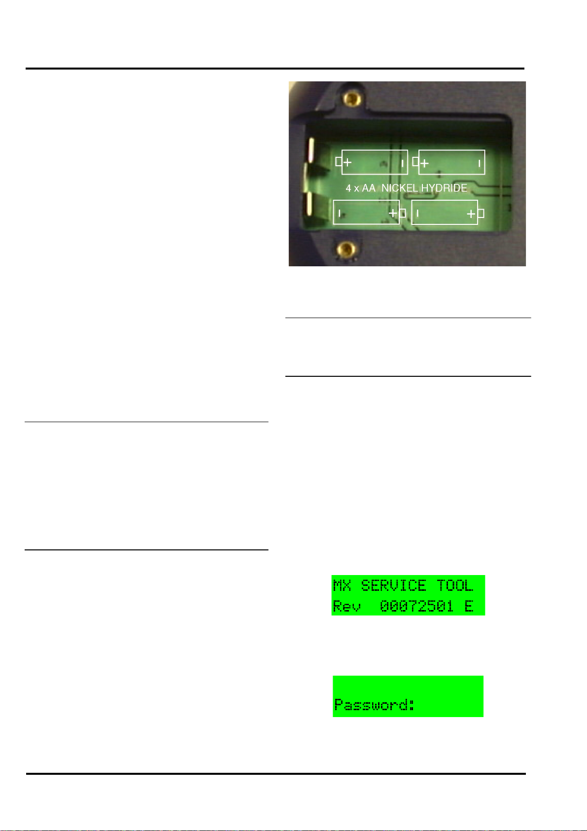
3.1.1 INSTALLING BATTERIES
To install/change the batteries, proceed as follows:
a) Unscrew the two screws on the base of the 801AP,
using a cross-point screwdriver, holding the battery
compartment cover whilst removing it.
b) Insert the batteries ensuring correct polarity as shown
inside the battery compartment.
c) Replace the battery compartment cover and screw
down.
CAUTION:
ENSURE ONLY NICKEL METAL HYDRIDE
RECHARGEABLE BATTERIES ARE USED.
3.1.2 CHARGING AND MAINS USE
The 801AP has its own built-in charging circuit, powered by
the mains adaptor. The batteries are boost-charged for 4-5
hours and reach full charge within 10 hours.
The 801AP can be powered from the mains supply using the
DC adaptor. If batteries are installed, this allows them to be
charged at the same time. For low battery indicator, see page 9.
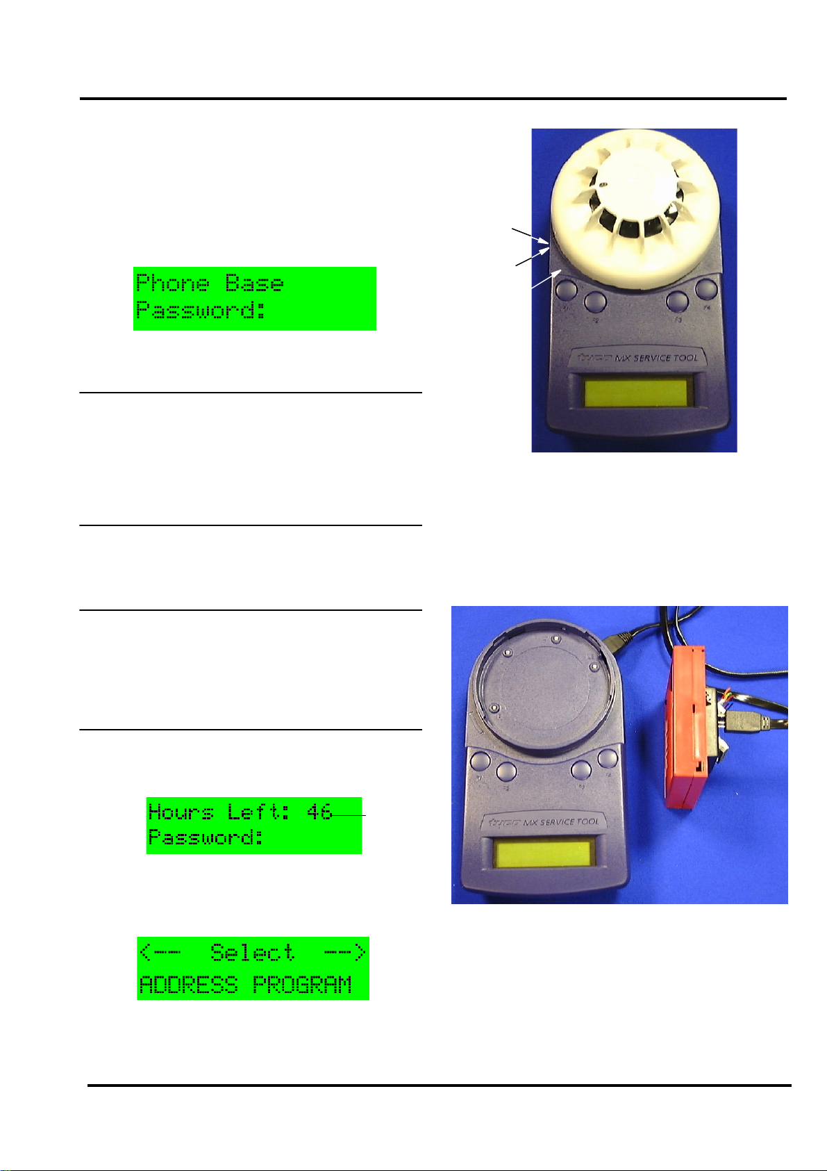
3.2 PASSWORD PROTECTION
The 801AP MX Service Tool is switched ON/OFF by pressing
any button for more than 3 seconds. The following example
screen showing the software revision number, is displayed for
2 seconds when the Service Tool is switched on:
Note that the ‘E’displayed stands for English version.
(appropriate letters are used for other languages). The Service
Tool then displays:
Note: The following information on Password
Protection is CRUCIAL to the operation of the
MX Service Tool.
Fig. 2 Battery Compartment

801AP
17A-05-AP
2 11/02
© 2002 Tyco Safety Products PAGE 3 of 10
Registered Office: First Floor North Building Walden CourtParsonage Lane Bishopís Stortford Herts CM23 5DB
EQUIPMENT:
PUBLICATION:
ISSUE No. &DATE:
The Service Tool requires a 6-digit password to be entered.
The password is different for each service tool and will be
issued by the respective branch office.
The password uses only the digits 1 to 4, and may be entered
by pressing the corresponding buttons F1 to F4; eg, button F1
to enter 1, button F2 to enter 2, etc.
The user has 3 attempts to enter the correct code. On the 4th
attempt the following screen is displayed:
The user must telephone the branch office to get the correct
6-digit password at this point.
WARNING:
FAILURE TO ENTER THE CORRECT
PASSWORD AT THE FOURTH ATTEMPT
WILL RESULT IN THE SERVICE TOOL
SWITCHING OFF AND ALLOWING ONLY ONE
ATTEMPT ON SUBSEQUENT POWERING UP
OF THE UNIT.
The password has an expiry time associated with it.
The hours left indicates the actual usage (switched on) time
remaining.
CAUTION:
ONCE THE HOURS LEFT REACHES ZERO,
THE SERVICE TOOL BECOMES
INOPERABLE AND MUST BE RETURNED TO
THE BRANCH OFFICE.
When there is less than 50hours, the expiry time appears. The
screen displays the expiry time in the form of ‘Hours Left’:
On successful entry of the password, the following screen is
displayed:
This is the start of the main menu options, which are
discussed further in para. 3.6.
(example)
3.3 CONNECTING TO A DEVICE
Detectors are inserted as shown in Fig. 3. Use the marking on
the service tool (above F1 button) to align the detector. Place
detector in position 1 to engage and then twist clockwise to
position 2 to lock.
Ancillaries are connected to the ‘AUX’socket using the
ancillary connection lead connector lead as shown in Fig. 4.
Note:
1) It is good practice to connect either a detector or
ancillary at any one time. However, the Service
Tool is equipped with a port interlock feature.
This allows an ancillary and a detector to be
connected at the same time. In such a case, the
detector will have priority for communication.
When the detector is removed, the ancillary will
be able to communicate.
Fig. 3 Connecting a detector
POSITION 2
POSITION 1
MARKING
Fig. 4 Connecting to an ancillary

801AP
17A-05-AP
2 11/02
PAGE 4 of 10
2) The 801AP may be connected to an ancillary
device that is also connected to and powered
from the addressable loop. However, a ‘No
Response’ fault for that device may be
generated at the Control Panel under these
conditions.
WARNING:
SPECIAL CARE MUST BE TAKEN WHEN
CONNECTING TO A DEVICE ON THE
ADDRESSABLE LOOP TO PREVENT
UNWANTED ACTION IN OTHER EQUIPMENT
EG, EXTINGUISHING SYSTEMS.
3.4 BUTTON OPERATION
The screen displays the start of the main menu as shown in
Fig. 5.
The main menu can always be identified by the word ‘Select’
between two arrows on the top line of the display. The
bottom line of the main menu displays the option.
The top line position of text is always shown in relation to the
F1-F4 buttons above. In the Main Menu:
•F1 scrolls left through the main menu options
•F2 or F3 select the menu option displayed
•F4 scrolls right through the main menu options
When an option is selected from the main menu, the display
uses the format shown in Fig. 6:
Fig. 5 First Display Screen of the main menu
The bottom line displays information to the user. The top
line displays the available options.
Note: The position of the options on the top line is
relative to the buttons.
Fig. 6 shows:
•F1 selecting ‘Back’
•F2 selecting ‘Write’
•F3 selecting ‘Dn’(for down)
•F4 selecting ‘Up’
In some cases there may be fewer options available.
Fig. 7 shows:
•F3 &F4 - no action
•F1 selecting ‘Menu’
•F2 selecting ‘Write’
Fig. 6 Example of Writing an address
Fig. 7 Example of Reading an address

801AP
17A-05-AP
2 11/02
© 2002 Tyco Safety Products PAGE 5 of 10
Registered Office: First Floor North Building Walden CourtParsonage Lane Bishopís Stortford Herts CM23 5DB
EQUIPMENT:
PUBLICATION:
ISSUE No. &DATE:
In Fig. 8 pressing F1 selects the ‘Menu’, F2-F4 are redundant
here.
3.5 FUNCTIONALITY
ADDRESS PROGRAM
(See also ‘STORE SETTINGS’to clear the used address
memory).
The main menu starts with ADDRESS PROGRAM. Press
buttons F2 or F3 to choose ‘Select’and the address of the
device is displayed (eg, address 4 ).
•Use ‘Write’to program the device with a new
address
•‘Menu’to return to the main menu
Note: Whenever ‘Menu’appears on the display, this
always returns to the main menu.
If ‘Write’is selected, the following screen is displayed:
•Use ‘Up’to increase the address number
•‘Dn’to decrease it
•‘Write’to program the address displayed
•‘Back’to return to the previous screen
Fig. 8 Example of Single Option
If ‘Write’is selected then the following message will appear
for 2 seconds:
This is followed by:
Having programmed an address, the Service Tool moves to
the next sequential address. This may be used or available.
If an address has already been used, the Service Tool
indicates:
The user has the choice to continue with a used address, or to
move to the next sequential address, using the up and down
(Dn) buttons.
If the user decides to use a previously used address, the
following screen is displayed:
Press ‘Write’and the Service Tool displays
‘PROGRAMMED OK’briefly and then displays the next
sequential address.
The Service Tool uses a memory map of the addresses that
have been programmed. To erase this, select ‘Store Settings’
from the main menu and choose Clear Used ‘ClU’.
ANALOGUE VALUES
ANALOGUE VALUES displays the analogue values of the
attached device.
The above example shows a device with 2 channels, eg, an
Optical/Heat detector, where channel 1 is the optical value
and channel 2 is the heat value. Press ‘Menu’to return to the
main menu.
CHANNEL 1 CHANNEL 2
SEE NOTE 1

801AP
17A-05-AP
2 11/02
PAGE 6 of 10
Note:
1) Only displayed if channel 3 is used on a device.
2) These are the values that the device would
transmit to the control panel. The values do NOT
include any calibration or correction factors.
MEASURE TEMP
This feature measures temperature in degrees Celsius and
degrees Fahrenheit, but is only available on detectors which
have a temperature sensing element, ie, Heat only, Optical &
Heat and CO &Heat detectors. A typical display is shown
in b):
MEASURE CO LEVEL
For CO detectors only. Gives values for CO levels in the
measuring environment. Normal value is zero PPM (parts-
per-million).
SELF TEST
This menu option performs a self test for detectors which
have this facility.
•Select SELF TEST to display the sensor
analogue values (a)
•Select ON to perform the self test; wait
10seconds to see if PASS is displayed (b)
•If FAIL is displayed, then the detector is
faulty and must be replaced
b)
a)
b)
Self Test is available on the following types of detectors:
•MX Ionisation
•MX Optical + Heat
(Optical sensing element only)
•MX CO + Heat
(CO sensing element only)
Note: Self test is NOT available for the heat sensing
channels of these detectors.
DIRTINESS
Available for Optical detectors only. Indicates the
contamination level of the optical chamber. Compares the
current optical analogue value as a percentage where 0%
would indicate that the analoguevalue has not changed since
manufacture, 100% would indicate that the analogue value
has risen to its maximum allowable value (the point at which
it would generate a fault).
At 80% or above, the detector should be replaced to avoid
the possibility of a fault occurring in the near future.
Note: Dirtiness can be displayed as a negative
number if the analogue value has fallen since
manufacture.
SERIAL NUMBER
Select SERIAL NUMBER from the main menu and the
unique preset factory number of the device in hexadecimal
will be displayed.
Note: This number cannot be changed by the user.
MANUFACTURE DATE
Selecting MANUFACTURE DATE shows the date of
manufacture of the device. Press ‘Menu’to return to the
main menu.

801AP
17A-05-AP
2 11/02
© 2002 Tyco Safety Products PAGE 7 of 10
Registered Office: First Floor North Building Walden CourtParsonage Lane Bishopís Stortford Herts CM23 5DB
EQUIPMENT:
PUBLICATION:
ISSUE No. &DATE:
COMMISSION DATE
Selecting COMMISSION DATE from the main menu
displays the date of device commissioning, which is
downloaded from the MX Front Panel (CIE) on the actual
date of commissioning. Press ‘Menu’to return to main menu.
DEVICE TYPE ID
DEVICE TYPE ID displays the addressable device Model
No. eg, 801PH. Select DEVICE TYPE ID and the detector
type is displayed.
LED MODE
The LED on the attached addressable device can be
programmed to blink, it will flash each time the detector is
polled. This can be done by selecting ‘Blnk’.
•To switch off the blinking select ‘Off’
•Test the LED status by selecting ‘Tst’.
This turns the LED ‘On’for 2 to 3
seconds
•Press ‘Men’to return to the main menu
For all devices using the MIM800 module (eg,
call points) or Intrinsically Safe varients (eg,
CP840Ex Callpoint), the LED can not be made
to illuminate unless the device is powered from
the addressable loop. Observe the warning (see
DIGITAL OUTPUTS) when connecting the
Service Tool to a device on the addressable
loop.
DIGITAL INPUTS
This menu option displays the status of the digital inputs as a
decimal number between 0to 255 for all addressabledevices.
For ancillaries RIM800 and APM800, the following status
messages are displayed (in addition to the decimal number):
DIGITAL OUTPUTS
The user may set the Digital Output of the addressable device
by using the following function buttons, F2 to F4:
Flashing cursor denotes the digit to be set.
•- moves the cursor one position to the
right
•Tog - toggles between 0 and 1 for each digit
•‘Set’- prompts the 801AP to send an
instruction to the addressable device
•‘Menu’- to return to the main menu options
WARNING:
WHEN USING THE SERVICE TOOL WITH AN
ANCILLARY DEVICE CONNECTED TO THE
ADDRESSABLE LOOP, MAKE SAFE ANY
ATTACHED EQUIPMENT, eg, EXTINGUISHING,
PLANT SHUTDOWN etc. UNLESS IT IS BEING
USED SPECIFICALLY FOR TESTING THE
ATTACHED EQUIPMENT.
RIM800 APM800
Relay Activ Device OK
Relay Inact Device Flt
Relay Fault

801AP
17A-05-AP
2 11/02
PAGE 8 of 10
After ‘Set’is selected, a message will appear asking for
confirmation of the action to send the data to the device,
as follows:
TEST RI TERMINAL
TEST RI TERMINAL tests the remote indicator output.
Selecting this menu option displays either PASS or FAIL.
TEST L2 TERMINAL
TEST L2 TERMINAL tests the functional base interface
output. Selecting this menu option displays either PASS or
FAIL.
BACKLIGHT
This controls the display backlight. If ‘On’is selected, the
display is illuminated for 6 seconds on each button press.
The display can also be temporarily illuminated by pressing
any two buttons simultaneously at any time.
Note: Use of the backlight will reduce battery life.
AUTO POWER OFF
AUTO POWER OFF is designed to save battery life. If there
have been no button presses during a preset time period, the
Service Tool automatically turns itself off. This menu option
allows the preset time period to be increased or decreased.
The timer is set by the user, afterwhich the Service Tool turns
itself off. The preset time period may be increased (or
decreased) firstly in 1 minute steps, then in 5 minute steps up
to 60 minutes maximum.
•Use ‘Dn’and ‘Up’to decrease or increase the
timer period
•Choose ‘Set’at the required level and then
press ‘Menu’to return to the main menu
STORE SETTINGS
The following settings may be changed during use and this
option enables the current values to be stored. The stored
values are recalled when the unit is next powered up. The
settings saved are: Auto Power-off time and Customer Code.
•Menu - returns to the menu option
•Def - returns to default settings
•ClU - clears list of previously used addresses
•Sto - select to save changed settings
Any settings which are changed and not stored will be lost
when the Service Tool powers down.
Note: Used addresses are stored automatically.
CUSTOMER CODE
CAUTION:
THIS MENU OPTION CHANGES THE
CUSTOMERCODE OFTHESERVICETOOLAND
SHOULD ONLY BE USED FOR DE-BUGGING
PURPOSES. IT SHOULD BE SET TO 254
NORMALLY.
Note:
1) Communication is only possible if the same
customer code is present in the addressable
device and the service tool.
2) The addressable device is manufactured with a
default code of 254. This is set in the device and
cannot be changed.

801AP
17A-05-AP
2 11/02
© 2002 Tyco Safety Products PAGE 9 of 10
Registered Office: First Floor North Building Walden CourtParsonage Lane Bishopís Stortford Herts CM23 5DB
EQUIPMENT:
PUBLICATION:
ISSUE No. &DATE:
3.6 ADDITIONAL FUNCTIONS
DEVICE POLLING
In all operations that retrieve data from an attached
device, the 801AP polls the attached device at a pre-
determined interval. This interval is 2 seconds for the
ADDRESS PROGRAM function and 5 seconds for all
other functions. The polling instants will be observable if
the LED is set to blink mode.
LOW BATTERY
This is indicated by a flashing cursor in the bottom right
of the LCD display.
The batteries must be charged using the mains adaptor
with its connecting lead plugged into the Service Tool dc
input socket.
CPU RESET
Note: This function is not normally used.
If the buttons or display are not responding correctly, the
Service Tool may be reset. This is done by pushing a
small jewellers type screwdriver into the pinhole on the
bottom of the Service Tool to actuate a switch.
When a CPU reset is carried out, the Service Tool will
start up as described in para 3.2 ‘Password Protection’.
INTRINSICALLY SAFE 800Ex DETECTORS
Intrinsically Safe 800Ex detectors can only be
programmed if an Ex dongle adaptor (supplied with the
EXI800) is fitted to the ‘AUX’port of the 801AP Service
Tool (see Fig. 9).
When using with Intrinsically Safe 800Ex devices, the
Service Tool must be used in a non hazardous safe area.
Fig. 9
Ex Dongle Adaptor
fitted to 801AP ‘AUX’
port
3.7 ACCESSORIES
3.7.1 ACCESSORY KIT (516.800.923 UK)
Consisting of:
Carry case
Car lighter adaptor
Shoulder strap
3.7.2 SPARES
Spare ancillary lead: 516.800.922 UK
Ancillary lead spare pins (bag of 10): 516.800.924
Spare batteries, pack of 4 x AA
Nickel Metal Hydride: 516.800.925

801AP
17A-05-AP
2 11/02
PAGE 10 of 10
MAIN MENU DISPLAY ACTIONS
‘Address Program’ Read/Writes the address of the connected addressable device
‘Analogue Values’ Displays the analogue values of the addressable device
‘Measure Temp.’ Measures temperature in degrees C and F (only available on detectors which have a
temperature sensing element)
‘Measure CO Level’ For CO detectors only. Gives values for CO levels in the measuring environment.
Normal value is zero PPM (parts-per-million)
‘Self Test’ Performs a self test if the detector has such a facility
‘Dirtiness’ Indicates the contamination level of the optical chamber expressed as a percentage,
where 100% is the fault level
‘Serial Number’ Displays the unique serial number of the addressable device
‘Manufacture Date’ Displays the date of manufacture of the device
‘Commission Date’ Displays the date of device commissioning
‘Device Type ID’ Displays the device type identification value
‘LED Mode’ •Blnk - flashes each time the device is polled
•Off - switches OFF the blinking option
•Tst - tests of the LED
‘Digital Inputs’Displays the status of the digital inputs in addressable devices
‘Digital Outputs’Allows the user to set the digital output of the addressable device
‘Test RI Terminal’Tests the Remote Indicator output
‘Test L2 Terminal’Tests the Functional Base interface output
‘Backlight’Switches the backlight ON/OFF
‘Auto-Power Off’•Dn - decreases the time
•Set - sets auto power OFF to the selected time
•Up - increases the time
‘Store Settings’This customises the Store Settings which are: Auto Power-off time and Customer Code.
•Def - returns to default settings
•ClU - clears ‘used addresses’ memory
•Sto - stores changed settings
‘Customer Code’Not normally used, but it should be set to the same as the customer code in the detector
Low Battery Indicates Low Battery by using a flashing cursor in the bottom right of the LCD display
CPU Reset Switch is accessed through a small hole at the rear of the unit near the label
Table 1: Functional Reference table
JM/jm 19th November 2002
This manual suits for next models
1
Table of contents