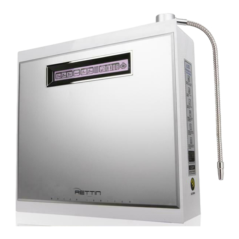
Tyent Rettin UCE Series User manual

Tyent Australia
User’s Manual
MADE IN KOREA
The consumer accepts any and all responsibility
and/or liability if replacement filters and/or parts
are notmanufacturer specific.
This product is subject to changes that enhance
its performance without prior notification.
pH Chart
How to Measure : Place 2-3 teaspoons(10-15ml)
of test water in a container and add 2-3 drops of
reagent. Then, mix well and check color of the water
with the pH chart above. (Color is dependent on
water quality and reagent)
The user should be responsible for failure or
improper selection or improper use of the
products such as use in any manner for
which the product was not originally
intended.

To Our Valued Customers Table of c o n t e n t s
under c o u n t e r ext re me
Table of c o n t e n t s
To Our Valued Customers
•We are not responsible for any accidents and/or malfunctions due to
the improper use of this machine.
•Please keep themanual and warranty card in a safe place, so that
it’s easily accessible when you need it.
•Please refer to this manual often when you have questions during
usage or when troubleshooting this unit.
Thank you for purchasing theUCE series Water Ionizer.
Please read all safety warnings and this User’s Manual carefully
before using this product to ensure proper product usage. (Keep the
manual handy for easy reference.)
Intended Use
23
This device creates functional alkaline, ionized water. Itchanges
the properties of regular tap water through the use of electrolysis.
Followingare thechanges normal tap water undergoes via this process:
•An increase or decrease in pH level
•Creation of negatively charged hydrogen ions (anti-oxidants)
•Smaller water molecule clusters for betterabsorption
•An increase in oxygen
•Purification through filtration
To Our Valued Customers
Table of Contents
Before Usage
Safety Precautions and Warnings
2
3
4
5
Dispenser Overview
10 Unit Overview
11 Product Features
12 Package Contents
16 Parts Drawing for Installation
17 Placement of the faucet tower harness connections
18 Under-Sink Installation
19 Dispenser Installation
20 Ionizer Installation
22 Customer Serviceable Parts
24 How to Change the Filters
25 How to Reset the Filters
26 Operation Touch Screen
27 Unit Usage
31 System Setup Method
33 Selecting Voice on/off 40
Cleaning Function
41 Eco Mode
42 Turbo Function
43 Usage Recommendations
44 Temperature Sensor
46 Unit Specifications
47 Troubleshooting 48
Product Warranty 51

Before Usage Safety Precautions and Warnings
under c o u n t er ext re me
Before Usage
DANGER (Red Warning Sign)
–indicates an imminent hazard
that could result in serious injury
or death. If you see this, stop the
use of this unit immediately.
WARNING (Orange Warning Sign)
–indicates a potential hazard that
could result in significant bodily harm
or damage to the unit. If you see this,
stop the use of this unit.
ATTENTION (Yellow Warning Sign)
–indicates a potential hazard that
could result in minor bodily harm or
damage to the unit.
Safety precautions are provided for the safe and proper use of this unit and can
prevent danger, bodily harm and/or possible damage due to misuse. Please make
sure you are familiar with all the safety precautions and warnings associated with
this unit.
Only use the unit with the correctvoltage.
Regarding Power Supply
PLEASE FOLLOW ALL INSTRUCTIONS WHEN YOU DRINK WATER CREATED BY
ELECTROLYSIS FROM THIS UNIT. (Hereinafter referred to as“functional water”)
Safety Precautions and Warnings
1.Do not drink functional water with medica-
tion. Use filtered Water instead.
2. Always consult your primary care physi-
cian before drinking functional water. Only
drink a small amount for the first week near
a neutral pH level. This will give the body
time to adjust to functional water during the
detoxification period.
3. If you notice any negative effects from
drinking functional water, stop drinking
immediately and consult with your primary
care physician about changes in your
body’s pH level.
4. Ifyou are currently under the care of a
primary care physician for an existing
condition, consult with your primary care
physician about how changes in pH and
other characteristics of functional water
could affect yourcondition.
5. If you suffer from gastric anacidity, kidney
failure or potassium excretion, you should
not drink functionalwater.
6. Verify the pH levels of the functional water
dispensed fromthis unit on a monthlybasis
to ensure proper function. This can be
done withthe supplied reagent drops and a
pH colorchart.
7. When switching from one pH to another, it is
good practice to let the water run for several
seconds before using.
8. It is common to drink half your body weight
in ounces. For example, if you weigh 180
pounds, it may be wise to drink 90 ounces
of water per day. This especially applies
after you have given your body some time
to adjust to the new pH level.
9. 9.5 to 9.8 pH is the recommended drinking
level for functional water. It is not recommen
ded to drink functional water above 10 pH.
10.If you wish to store functional water, use a
glass, stainless steel or other non-leaching
materialand store in the refrigerator.
11.
Never run hot water through this unit.
12.
Never drink acidicwater.
Do not use power surge protectors with this
unit. Use unit with its own dedicated power
source.
Do notpull thepower cord. Never touch power
cord or power outlet with wethands.
Do notuse ifthe power cord is damaged or in a
loose power outlet.
Please always use a grounded power outlet.
Unplug the power cord during general mainte-
nance, repair, inspection and while replacing
parts.
45

under c o u n t e r ext reme
Safety Precautions and Warnings
Usage
benzene
Do not place ANY objects on top of this unit
regardless of how small.
To reduce the risk of electric shock, do not
remove cover; no user-serviceable parts inside.
Refer servicing to qualified service personnel.
Removing the cover will void thewarranty.
Do not spray water on the main unit. Do not
clean with a damp cloth, benzene or other
chemicals, which mayleak into the unit.
Do not store unit near chemicals, food, metals
or medication.
Do not poke or scratch thetouch pad or LCD
display with sharp objects.
It is beneficial for the maintenance of the
machine to run a strong acidic level for a period
of 5minute cycles twice weekly. This will help to
maintain a clean chamber.
In case of strange noises, burning odor or
smoke, unplug the power cord immediately and
refer servicing to qualified service personnel.
In case unit leaks (other than hoses) or is
standing in a puddle of water, shut off water
supply, unplug the power cord and refer
servicing to qualified service personnel.
Replace filters every 6 months to optimize the
purification performance of this unit even if the
replacement indicator light isn’t turned on.
Do not forcibly bend, squeeze, damage or
crush the power cord under heavy objects.
Do not use alkaline or acidic water in fish bowls
or aquariums. The sudden change in pH could
be harmful or fatalto some marine life.
In areas of hard water(Calcium scaling present
on faucets) notify service provider and install
cell safe anti scale Pre-filter, protects against
scaling of ionizer.
67

under c o u n t er ext re me
Safety Precautions and Warnings
Do not place this unit near heat sources.
Do not connect waterline to a hotwater supply.
Do not place this unit on an uneven surface. Do
notdrop or use excessive force on thisunit.
Installation Storage
Do not use unfit raw water in accordance to the
standards of the water service act.
89
In the case where the unit isn’t used over a
long period of time, shut off the valve and
unplug the power cord.
Remove the filters and shake out as much as
possible. Store in plastic bag in refrigerator to
avoid bacteria growth in filters.
In case the original packaging is not available,
cover the unit in plastic to avoid scratching the
surface.
Carefully remove this unit from packaging.
Keep original packaging for future storage and
unit transportation.
Store unit in itsoriginal packaging in a cool, dry
place when not in use.
Do notuse in areas of high humidityand/or high
temperature.

under c o u n t e r ext reme
Unit Overview
Dispenser Overview
Dispenser Overview Unit Overview
Front View Front View
Rear View Rear View
●1 Front Case
●2 Front Cover
●3 Front Door Case
●1 Jog Dial
●2 Water Outlet
Pipe
●3 Drain Pipe
●4 Fixing Nut
●5Speaker
●1 Hanging Groove
●2 Rear Case
●3 Product Sticker
●4 Power Swich
●5Fuse
●6 Power Cord
4
5
6
Bottom View
●1 Alkaline
Outlet
●4 MCU Cable
5
●2 Acid Outlet
●5 Power
Code
●3 Tap Water
Inlet
29.5cm
11.6inch
17.2cm
6.8inch
3.3cm
1.3inch
13.2cm
5.2inch
11cm
4.3inch
16cm
6.3inch
35cm
13.8inch
13.2cm
5.2inch
36cm
14.1inch
38.2cm
15inch
SIN
K
5cm
2inch
10 11

3. GERMAN
4. FRENCH
5. ITALIAN
6. SPANISH
1. KOREAN
2. ENGLISH
3. GERMAN
4. FRENCH
under c o u n t e r ext reme
Product Features
Product Features
Product Features
GUI [Graphical User Interface]
Jog Dial & Touch with2 way Operation Compatibility
Offering bothKitchen Space and Ultimate Beauty
A DESIGN MASTERPIECE
FULL TOUCH LCD –TRANSFORMATION AT YOUR FINGERTIP
JOG DIAL & TOUCH
Light and Screen Indicators forWaterDischarge Detection
Excellent MP3 Sound Quality withGuided Support
CAREFUL CONSIDERATION FOR THE USER
Upgraded Power Turbo System
PowerSMPS PowerSupply System
Electrodes withRound-Mesh Plate Technology
MORE POWERFUL SYSTEM ENGINE !
The RETTIN Under Counter Extreme Water Ionizer not only attracts
person’s gaze with its well-differentiated appearance, but also
helps to upgrade your kitchen’s interior decoration with a neat and
luxurious expression.
Turbo upgrades to the SMPS Power Supply system produce both
the acid turbo water and strong alkali water you need!
Power SMPS Power Supply System provides the maximum
instantaneous output needed to produce the highly stable electric
power required for each phase of electrolysis.
These Platinum-Coated Titanium Plates are made with highly
stable, durable mesh technology that enhances the instantaneous
electrolysis efficiency.
Changes to the LCD screen and Jog Dial light can be easily
identified to check each selected phase.
Functions under operation can be further identified by the top
quality voice guidedsystem.
Multiple Languages Supported
Diversified language guide support is available by selecting 1of 6
languages featured fromacross the world.
The Industry’s First Full Touch Screen Panel
The Full Touch Screen Panel System automatically activates the
unit’s operations through a simple touch to the desired icon
displayed on the screen.
Touch LCD Screen witha Clear Picture Tone
A 262,000 Color Touch LCD Display provides diverse information
in true vivid colors for user convenience.
A Graphical User Interface is designed specifically for ease of use
and operation. Communication between the user and ionizer has
never been this simple!
Choose from either the Jog Dial or the Touch Screen Panel
system–both are available with 2 way operation compatibility and
are easy to use at yourconvenience.
11:00a
80% 80%
12 13

under c o u n t e r ext reme
Product Features
Product Features
Earth-Friendly Technology wheninECO Mode
True energysaving is accomplishedwith ultra low powerconsumption
during periods of non-use.
CARE FOR THE ENVIRONMENT
Temperature Sensor Function forSafe Operation
Water Discharge Nozzle withDirectionalControl
The water discharge direction may be adjusted to many diverse
angles based on user preference.
Automatic WaterDischarge Interruption Function
In order to prevent the overflow of water due to user negligence,
the waterdischarge is automatically stopped after15 minutesof use.
Automatic Electrolysis Tank Cleaning Function
The interior of the Electrolysis Tank is automatically cleaned on a
regular basis, ensuring stable electrolysis operating conditions.
Automatic Memory Function
The lastfunction used by the user is automaticallymemorizedand
displayed on the Standby Screen for fast and convenient operation.
WaterPurificationthrougha Clean Process
FRESH,PURIFIEDWATERISAMUSTALONGWITHHEALTHY MINERALS!
Convenience of Operating Condition Setting System
Super Simple Filter Replacement System
pH Control Function
Respective alkali, acid & turbo phases can be easily controlled by
the user.
Self Diagnosis Function
When the condition of the source water is not suitable, the water
discharge is automatically suspended, displaying a Warning Sign
on screen.
Filter Usage Indication and Replacement Time Guide
SELFMAINTENANCEMADEEASY–FROMINSTALLATIONTOAFTER-SERVICE
14 15
If the temperature of the source water exceeds 95℉(35℃) then
water will stop flowing and a warning message will appear on the
screen. Perfect, seamless elimination of foreign substances including
residual chlorine, organic & inorganic compounds through the
filtering process using functional UF and ∏Ceramic materials,
enhancing the alkali water producing condition.
Level of filter usage can be identified through the LCD Screen on a
real time basis. The recommended replacement time is
automatically displayed on the screen witha voice guide.
A simple filter replacement system along with one-touch Filter
Usage Initialization Setting System makes filter management easy
for any one.
Easy Setting System familiar to common users is employed,
allowing the convenience of setting or canceling the desired
through the LCD Screen.

under c o u n t e r ext reme
Parts Drawing f o r Installation
Package C on tent s
Parts Drawing f o r InstallationPackage C ont ent s
Ionizer
rubber packing
(2EA)
Wrench
pH Testing
Solution Bottle
User’s Manual
Tap Water
hose
Acid hose
(Orange)
&
Alkaline hose
(White)
WaterOutlet Pipe
StemElbows
(3EA)
dispenser
fixing nut
Cable Tie
T-Adapter
Dispenser
Rubber packing
Rubber packing
Fixing
nut
Union connector
Stem elbow
Acid outlet
Tap water inlet Alkaline hose
Acid hose
MCU cable
Alkaline outlet Tap waterhose
Acid hose
Alkaline hose
MCU
cable
Adapter
Ionizer
Tap water
hose
MCU cable connector
Cable tie
Bottom
Picture of components can be different fromthe real ones, and some itemsmaybe changed according to the situation.
16 17

under c o u n t e r ext reme
Under-Sink Installation
1. Shut off both hot and cold water main supply at pipe under the sink.
2. Locate the cold water supply line valve.
3. Disconnect faucet cold water supply line from main cold water pipe–use
towel to catch small amount of water that may come from faucet supply
line.
4. When connecting T-Adapter to cold waterpipe,be sure to use plumbing
pipe thread seal tape (not included) to prevent leaks.
5. Reconnect faucet cold water supply line to T-Adapter. (now secured
to main cold waterpipe)
6. Be sure all connections are secure but do not over tighten.
※Do not turn on main water supply until all hoses are properly installed
to the unit.
Placement of the faucet tower harness connections
When Installing the UCE faucet tower, it is a good idea to secure the
harness connections to the side of the tower nut that secures the tower to
the counter, this way if any water leakage occurs fromthe counter top it will
not drain or leak into harness connectors and cause corrosion on the
connectors.
Placement
18 19
of the faucet tower harness con ne ct i on s

under c o u n t e r ext reme
Dispenser Installation
6 Place the assembled dispenser into the
drilled hole.
8 Tighten the fixing nut underneath thesink.
(do not over tighten)
7Insert the second rubber O-ring in the
assembled dispenser located underneath
the sink.
5 Insert one of the provided rubber O-Rings
in the assembled dispenser.
32mm
Drain Pipe
Water Outlet Pipe
Dispenser Installation
1 First, unscrew the large nut fromthe bottom of
the dispenser.
2 Press the outflow pipes into the holes of the
dispenser.
※upper hole: water outlet pipe - 152 mm (6 inches)
※lower hole : drain pipe - 102 mm (4 inches)
3Connect each hose from the dispenser to a
union connector. Connect each hose from
the ionizer to the union connector. When you
connect the hoses, please match the hoses
by color:
i.e., orange‒orange, white‒white
20 21
from Ionizer
from Dispenser
4 Use a 32mm(1 1
/4inch) drill bittodrill a hole.

under c o u n t e r ext reme
Ionizer Installation
Caution
In the event of a power failure
Remove thepower cord fromelectrical socket and shut offsource water
valve.
6 Plug in the power cord and turnon the unit.
※INTRO Screen appears only when
Initial Power is supplied.
alkaline hose
acid hose
tap water inlet
Ionizer Installation
2 Connect the hoses of the dispenser to the
stemelbows. (when you connect the hoses,
use orange for the acid hose and white for
the alkaline hose)
3 Connect the MCU cable of the dispenser to
the MCU cable on the bottomof the ionizer.
4Connect the hose from the inflow hole to
the cold water supply at the under-sink
T-Adapter.
5Make sure all hose connections are firmly
seated in the correct holes, both on the
unit and at the watersupply.
1Press the stem elbows into the water inflow,
alkali outlet and acidic outlet located on the
bottom of the ionizer.
22 23

Primary Filter: 1st Filter
Recommended filter replacement cycle:
951.0gallons (3,600 L) / Every 6 months
Removes harmful chemicals like chlorine,
compounds such as agrichemicals and
detergents, large suspended matters like rust
and sediments as well as other volatile organic
compounds through an efficient, activated
absorption method. It also eliminates bad
smells and any remaining dissolved chlorine.
1stFilter
Secondary Filter: 2nd Filter
Recommended filter replacement cycle:
951.0gallons (3,600 L) / Every 6 months
0.01 micrometer artificial film filters contaminated
materials including ordinary bacteria while
maintaining essential minerals in the water.
2ndFilter
The life of the filter may vary greatly due to use, water pressure, water quality and
seasonal changes. Filters may need to be replaced sooner than the scheduled
time due to these varying conditions, as you may notice reduced water quality or
water tastechanging for the worse.
Customer Serviceable Parts
ATTENTION: The consumer accepts any and all responsibility and/or liability if
replacement filters and/or parts are not manufacturer specific. This unit contains
high-performance purifying filtersand an advanced control system.
under c o u n t e r ext reme
H o w t o ch ang e t h e Filters
Customer Serviceable Parts
H o w t o Change t h e Filters
1Turn the power off and unplug the power cord. Shut
off the water supply to the unit. Make sure the faucet
is shut off.
2 Openthe frontdooroftheunit.Bewareof the sharp
corners of the cover of the unitwhen opening.
3Pull the filter towards you so that it will be easier to
turn. The filter will turn more freely when tilted at a
slight angle. Remove the filter by rotating the filter
counter-clockwise. Install the new filter by turning
it clockwise. Hand tighten only. Tilt the filter back
intoitsoriginalupright position.
4 Close the coverof the unit.
5 Plugthe power cord back in, re-engage the water
supplyand switch the unitback on.
24 25
open
separate
connect

under c o u n t e r ext re me
How to reset the Filters
Operation Touch Screen
11:00a
80% 80%
Operation Touch Screen
Display line oftheset status
Functional wateroperation
Display line of filter usage
( default : 00% )
Icon : description
Set up
Voice on
Voice off
Cleaning
Eco mode on
Eco modeoff
Filter 1usage
Filter 2 usage
Alkaline level 1
Alkaline level 2
Alkaline level 3
Purified water
Turbo water
Acidic level 1
Acidic level2
Acidic level 3
1 standby mode
11:00a
H o w t o Reset t h e Filters
H o w t o Change t h e Fuse
80% 80%
1. First Filter Reset
①Press the bottompart of LCD Screen.
MENU Window appears upper the bottompart of LCD Screen.
②To initialize, press the“F1 RESET”icon 2 times.
※LCD : percentage (%)of initialization of filter
2. Second Filter Reset
①Press the bottompart of LCD Screen.
MENU Window appears upper the bottompart of LCD Screen.
②To initialize, press the“F2 RESET”icon 2 times.
※LCD : percentage (%)of initialization of filter
CAUTION! Use the Filter Initialization Icon only after Filter is changed.
1. Unplug the power cord.
2. Locate the fuse cap on the lower back of the unit and turn it counter-
clockwise to remove it.
3. Pull out the blown fuse and insert a new fuse.
4. Replace the fuse cap.
Important Information
Please be sure tocontactmanufacturertoobtainthe correctfuse. Customeraccepts all
reponsibility for damage to unit and other property due to the installation of incorrect fuse.
: Filter 1reset
: Filter 2reset
7
26 27

under c o u n t e r ext reme
Operation Touch Screen
15:00
Selectedmode
Autoflowstop
timeindicator
Workingindicator
3 LCD Display
1
2
11:00a
80% 80%
11:00
a
1 2
80%
34
80%
1 Set up mode (page 34)
2 Voice on/off (page40)
3 Cleaning (page 41)
4 Eco mode on/off (page42)
1 Filter 1reset
2 Filter 2reset
Use the Filter Initialization Icon only after the filters have
been changed.
Push the upper part of LCD Screen. MENU Window appears below
the upper part of LCDScreen.
Push the bottompart of LCD Screen. MENU Window appears above
the bottom part of the LCD Screen.
CA UTION!
2 Menu window
DISPLAYS COLORS
Backlight of LCD display will match the pH level color according to water pH
level being used after icon is pressed.
15:00
Turbo
RedColor
05:00
DarkBlueColor
15:00
Alkaline Water 1 Alkaline Water 2 Alkaline Water 3
PurpleColor
15:00
(Approx 8.0 pH) (Approx 9.0 pH) (Approx 10.0 pH)
light BlueColor
15:00 15:00 15:00
Acidic Water 1 Acidic Water 2 Acidic Water 3
(Approx 5.5 pH) (Approx 4.5 pH) (Approx 3.5pH)
Light Yellow Color Light OrangeColor LightPinkColor
15:00
28 29
Clean Water
(Approx 7.0pH)
GreenColor

under c o u n t er ext re me
Unit usage
Operation Touch Screen
:15
CAUTIONS in using the TOUCH Screen
4 Message Display
When this is displayed, it is timeto
replace the filters (p.25~26)
When this is displayed, water inside
the unit is higher than 95℉(35℃). The
water supply will then be shut off and
the unit will stop operating. (p.46)
When the automatic
cleaning time comes,
WARNING is displayed.
When this is displayed,
the unit is being cleaned
which can be done
automatically and/or
manually.
1. Due to the uniqueness of the TOUCH Screen, TOUCH is not recognized if
pushed by more than one finger. Please push with only one finger and be
careful of contamination to the screen thatmay cause damage to the TOUCH.
2. Be careful of electrostatic materials near the TOUCH Screen. Stimulation from
such materials may cause damage to the TOUCH.
3. Screen may not be seen well under direct sunlight.
4. Do not push the Screen hard with sharp or pointy objects.
When this is been a suspension of
water supplied to the unit, issuing this
messagepriorto stoppingwateroutflow.
15:00
11:00a
80% 80%
14:39
Unit usage
1 Press thedesired icon on theLCD screen
2 Wateroutflow starts. screen displays current
level and stoptime.
3 Press thescreen to stop theflowof water.
4 When done, screen moves to last used icon
and, into stand by mode.
1 When using t h e TOUCH Screen
11:00a
80% 80%
The water level you choose willflow
throughwateroutletpipe(upper).
30 31

under c o u n t e r ext reme
SYSTEM SETUP METHO
D
Uni
t
usage
SYSTEM SETUP METHOD
1
◀
▶
I
2
◀
▶
I
3
◀
▶
I
14:39
15:00
11:00a
80% 80%
Turn Dialeitherdirection to select
function,
white means it’s selected.
Screen changes to selected color.
Push center of Dial to start water
outflow.
Push center of Dialto stop water
outflow.
4 When done, screen moves to last used icon
and, into stand by mode.
2 When using t h e JOG DIAL
11:00a
80% 80%
The water level you choose willflow
throughwateroutletpipe(upper).
pH Level Adjustment
pH Chart
Just remember when testing the pH be sure to allow unit to run for 2
minutes before taking a sample of the water. If you have to adjust
percentage, after adjusting, run an additional 2 minutes before taking
sample. When testing pH values we like to use 2 Tablespoons of the water
being produced and 4 Drops of the Re-Agent in a clear glass.
The minimum and maximum Turbo waters produce will be dependent on
the water source quality. Set Turbo at 100% for maximum pH levels, these
levels can range normallyas follows:
Color of PH Testing of Each Level :
Alkaline Turbo (Dark Purple)
Acid Turbo (Red)
Alkaline Level 1= Approx 8.0 pH (light blue)
Alkaline Level 2 = Approx 9.0 pH (dark blue)
Alkaline Level 3 = Approx 10.0pH (Purple) H2O =
Approx 7.0 pH (green) Purified Water Acid Level 1
= Approx 5.5 pH (lightyellow) Acid Level 2 =
Approx 4.5 pH (lightorange) Acid Level 3 =
Approx 3.5 pH (light pink)
※pH valueindicatedfor each levelis based on standardizedtestresult which have used average tap water.
32 33

under c o u n t e r ext reme
SYSTE
M
SETU
P
METHO
D
SYSTE
M
SETU
P
METHO
D
2
: ACD pH level up (08%, 09%, 10%...)
◀
▶
I
or
: ACD pH level down(06%, 05%, 04%...)
◀
▶
I
or
Acidic pH Level Adjustment
11:00a
80% 80%
2 Press thesetup icon.
1 Press thetopleftcorner of screen. MENU
options will fall below upper partof screen.
5
ACD 1ST: 07%
ACD2ND : 25%
ACD 3RD : 30%
ACD 1ST: 07%
ACD2ND : 25%
ACD 3RD : 30%
3 Press“ACIDICpH”
4 Press desired level.
11:00a
80% 80%
SYSTEM SETUP METHOD
3 Press“ALKALI pH”
4 Press desired level.
2 Press thesetup icon.
1 Press thetopleftcorner of screen. MENU
options will fall below upper partof screen.
ALK
1ST
:
08%
ALK
2ND
:
10%
ALK
3RD
:
16%
TURBO
:
95%
: ALK pH level up (09%, 10%, 11%...)
5
◀
▶
I
or
: ALK pH level down(07%, 06%, 05%...)
◀
▶
I
or
1 ALKALIpH Level Adjustment
Push RETURN icon for previousmenu screen. Voice says “:Applied”
Push RETURN icon again to complete set up.
Voice says :“Set up was completed”
ALK
1ST
:
08%
ALK
2ND
:
10%
ALK
3RD
:
16%
TURBO
:
95%
Turn the Jog Dial clockwise (or counter clockwise) to
select desired level. Press the PUSH On/Off button of
the jog dial to make selection.
When using the Jog Dial
◀
▶
I
If UP/DOWN Icon is pushed, digital number moves by one step.
Turn the Jog Dial clockwise (or counter clockwise) to
select“ALKALI pH”. Press the PUSH On/Off button of
the jog dial to make selection.
When using the Jog Dial
◀
▶
I
Backcolor
Orange highlight shows current position on menu.
A blue highlight means that changes to that setting are possible.
Push RETURN icon for previousmenu screen. Voice says “:Applied”
Push RETURN icon again to complete set up.
Voice says :“Set up was completed”
Backcolor
Orange highlight shows current position on menu.
A blue highlight means that changes to that settingare possible.
Turn the Jog Dial clockwise (or counter clockwise) to
select desired level. Press the PUSH On/Off button of
the jog dial to make selection.
When using the Jog Dial
◀
▶
I
If UP/DOWN Icon is pushed, digital number moves by one step.
Turn the Jog Dial clockwise (or counter clockwise) to
select“ACIDIC pH”. Press the PUSH On/Off button of
the jog dial to make selection.
When using the Jog Dial
◀
▶
I
34 35

under c o u n t e r ext reme
SYSTE
M
SETU
P
METHO
D
SYSTE
M
SETU
P
METHO
D
11:00a
80% 80%
11:00a
80% 80%
3Press“VOLUME”
4
4 Volume Level Adjustment
3. GERMAN
4. FRENCH
5. ITALIAN
6. SPANISH
1.
KOREAN
2.
ENGLISH
3.
GERMAN
4.
FRENCH
4 Press desired language.
KOREAN, ENGLISH, GERMAN,
FRENCH, ITALIAN, SPANISH
1
Press thesetup icon.
2
Press thetopleftcorner of screen. MENU
options will fall below upper partof screen.
1
2 Press thesetup icon.
Press thetopleftcorner of screen. MENU
options will fall below upper partof screen.
3 LANGUAGE MODE
5
3Press“LANGUAGE”
◀
▶
I
Turn the Jog Dial clockwise
(or counter clockwise) to select
desired language.
: Volume up (0 -10
step)
◀
▶
I
or
: Volume down (0 -10
step)
or
◀
▶
I
Pressing this icon will let you hear current volume.
Pressing the Push On/Off button on jog dial will let
you hear current volume.
Push RETURN icon for previousmenuscreen. Voice says “:App l ied”
Push RETURN icon again to complete set up.
Voice says :“Set up was completed”
If UP/DOWN Icon is pushed, digital number moves by one step.
Turn the Jog Dial clockwise (or counter clockwise) to
select“LANGUAGE”. Press the PUSH On/Off button of
the jog dial to make selection.
When using the Jog Dial
◀
▶
I
Turn the Jog Dial clockwise (or counter clockwise) to
select“VOLUME”. Press the PUSH On/Off button of the
jog dial to makeselection.
When using the Jog Dial
◀
▶
I
Supported language
Push RETURN icon for previousmenuscreen. Voice says “:Appl ied”
Push RETURN icon again to complete set up.
Voice says :“Set up was completed”
If UP/DOWN Icon is pushed, digital number moves by one step.
36 37

Year 01
Month 10
Day
Hour 18
Min 0
under c o u n t e r ext reme
SYSTE
M
SETU
P
METHO
D
SYSTE
M
SETU
P
METHO
D
11:00a
80% 80%
11:00a
80% 80%
※Do not press with sharp or pointy
objects.
3Press“TIME”
5
4 Adjustment timeand datewiththearrows :
ⓐYear ⓑMonth
ⓒDay ⓓHour
ⓔMinute
Time set up is complete.
1
2 Press thesetup icon.
Press the topleftcorner of screen. MENU
options willfallbelow upper partof screen. 1
2 Press thesetup icon.
Press the top leftcorner of screen. MENU
options will fall below upper partof screen.
5 Setting t h e TIME 6TOUCH
3Press“TOUCH”
4Each time a crosshair appears
on the screen, touch the center
of it with your finger to complete
calibration.
5 Once calibration is complete,display will move to
setting mode automatically.
◀
I
◀
I
or : for up or : for down
When using the Jog Dial
Turn the Jog Dial clockwise (or counter clockwise) to
select“TIME”. Press the PUSH On/Off button of the jog
dial to make selection.
◀
▶
I
When using the Jog Dial
Turn the Jog Dial clockwise (or counter clockwise) to
select“TOUCH”. Press the PUSH On/Off button of the
jog dial to makeselection.
◀
▶
I
If UP/DOWN Icon is pushed, digital number moves by one step.
Push RETURN icon for previousmenuscreen. Voice says “: Applied”
Push RETURN icon again to complete set up.
Voice says :“Set up was completed”
Backcolor
Orange highlight shows current position on menu.
A blue highlight means that changes to that settingare possible.
※If you fail 2 times, display will move tosetting mode
automatically.
Year 01
Month 10
Day
Hour
Min
18
0
38 39
This manual suits for next models
1
Table of contents
Other Tyent Water Filtration System manuals
Popular Water Filtration System manuals by other brands

Danfoss
Danfoss VLT AAF006 Service manual

AquaTools
AquaTools AT8236 owner's manual

Zodiac
Zodiac TRi Series Instructions for installation and use

Perma-Trade
Perma-Trade permasolvent primus 2.1 operating instructions

Clean Water Systems
Clean Water Systems Birm 7800 Installation & start?up guide

PristineHydro
PristineHydro WRS-UC3 installation manual