manuals.online logo
Brands
  1. Home
  2. •
  3. Brands
  4. •
  5. Tylo
  6. •
  7. Plumbing Product
  8. •
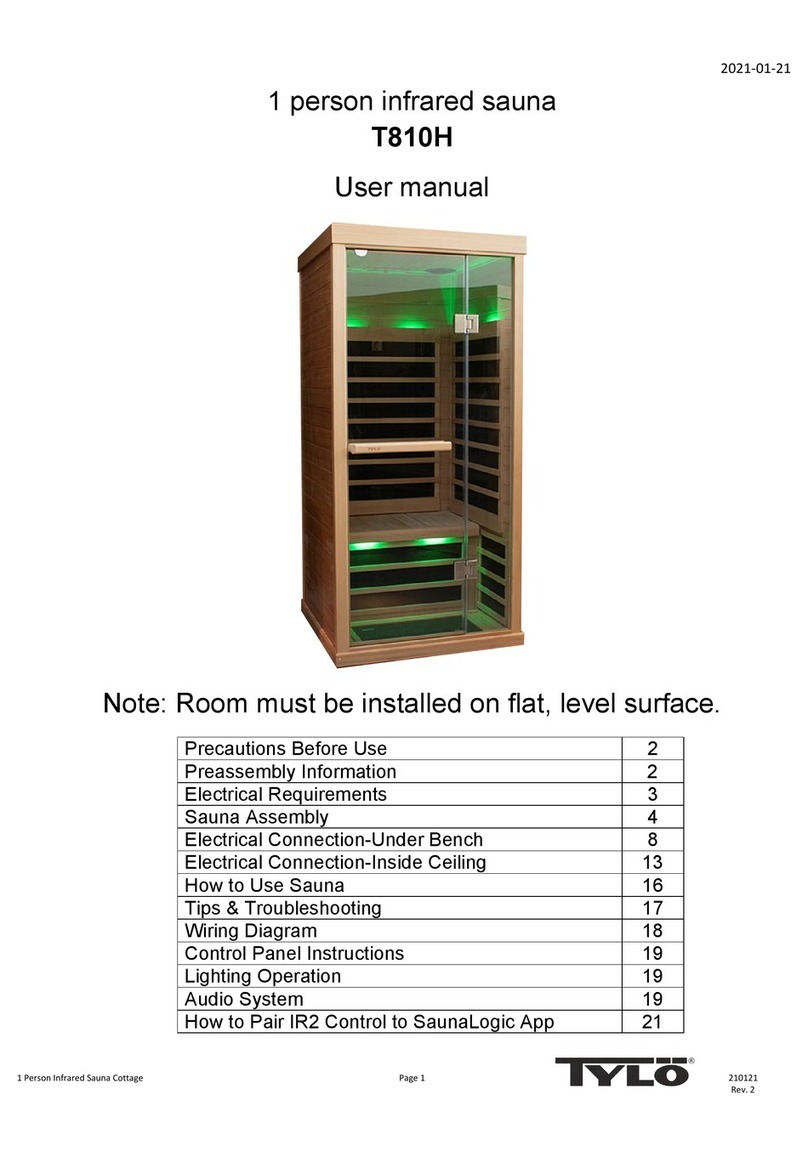
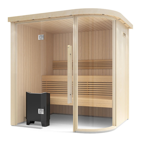
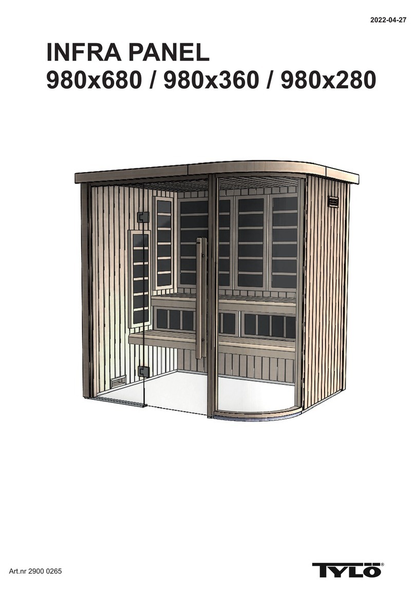
  9. Tylo Sauna i1115 Corner User manual

Tylo Sauna i1115 Corner User manual

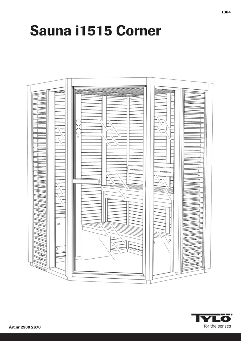
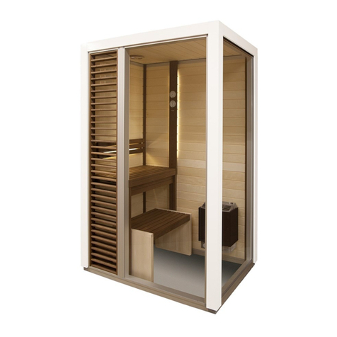
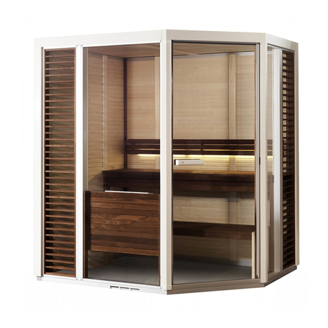
Sauna i1115 Corner
2017-04-13
Art.nr 2900 2665
2090 mm
1095 mm
890 mm
1
7
8
4
23
WG
G
D
5
G
WW
6
W
1495 mm
490 mm
855 mm
W
9
1095 mm
890 mm
1
7
8
4
2
3
W
G
G
D
5
G
W
W
6
W
1495 mm
490 mm
855 mm
W
9
Det här är två exempel på montering av rummet. Det är
layout 1 som visas i monteringsanvisningen. Siffrorna visar
i vilken ordning väggarna skall monteras. Väggarna på
layouten är även märkta med materialet. G= glas, W=
Träpanel, D= Glasdörr.
Shown here are two examples of how to assemble the
room. These assembly and installation instructions
describe the procedure for assembling Layout 1. The
numbers indicate the order in which the walls are to be
assembled. The layout diagrams use the following codes to
indicate materials/components: G= glass, W= wooden
panelling, D= glass door.
Dies sind zwei Beispiele für die Montage der Kabine. Die
Montageanleitung bezieht sich auf Layout 1. Die Ziffern
beziehen sich auf die Reihenfolge, in der die Wände zu
montieren sind. Die Buchstaben bezeichnen das jeweilige
Wandmaterial G= Glas, W= Holzvertäfelung, D= Glastür.
Voici deux exemples de montage de la cabine. C'est la
configuration 1 qui est illustrée par les instructions de
montage. Les chiffres indiquent l'ordre de montage des
cloisons. Sur l'illustration, les cloisons portent également
une lettre désignant le matériau. G = verre, W = panneau
de bois, D = porte vitrée.
Два примера монтажа комнаты. Это монтажная схема
1, показанная в инструкции по монтажу. Цифрами
показан порядок монтажа стен. Стенки на монтажной
схеме отмечены вместе с материалом. стекло, W=G=
деревянная панель D= стеклянная дверь.,
Są tu pokazane dwa przykłady aranżacji kabiny. Poniższa
instrukcja montażu i instalacji opisuje procedurę dla
schematu nr 1. Cyfry wskazują kolejność w jakiej ścianki
mają być montowane. Na schematach są zastosowane
następujące kody wskazujące materiały/moduły: G= szyba,
W= panel drewniany, D= drzwi szklane.
Layout 1
Configuration 1
Монтажная схема 1
Układ nr 1
Layout 2
Configuration 2
Монтажная схема 2
Układ nr 2
Min. 100 mm - Vid montering
Min. 100 mm - During assembly/installation
Mind. 100 mm - Bei Montage
Mini. 100 mm - Lors du montage
-Мин. 100 мм При монтаже
Min. 0 mm Podczas montażu/instalacji10 -
W
Trä
Wood
Holz
Bois
Дерево
Drewno
Beskrivning av de olika väggtyperna
Description of different types of wall construction
Beschreibung der einzelnen Wandtypen
Description des différents types de cloison
Описание различных типов стенок
Opis różnych modułów ścianek
GGlas
Glass
Glas
Verre
Стекло
Szkło
Upp
Up
Oben
Haut
Верх
Do góry
Ner
Down
Unten
Bas
Низ
Na dół
Packning
Packing
Dichtung
Joint
Прокладка
Uszczelka
Packning
Packing
Dichtung
Joint
Прокладка
Uszczelka
Insida
Inside
Innenseite
Intérieur
Внутр.
Wewnątrz
Utsida
Outside
Außenseite
Extérieur
Наруж.
Na zewnątrz
DUpp
Up
Oben
Haut
Верх
Do góry
Ner
Down
Unten
Bas
Низ
Na dół
Packning
Packing
Dichtung
Joint
Прокладка
Uszczelka
Insida
Inside
Innenseite
Intérieur
Внутр.
Wewnątrz
Utsida
Outside
Außenseite
Extérieur
Наруж.
Na zewnątrz
Upp
Up
Oben
Haut
Верх
Do góry
Ner
Down
Unten
Bas
Низ
Na dół
Insida
Inside
Innenseite
Intérieur
Внутр.
Wewnątrz
Utsida
Outside
Außenseite
Extérieur
Наруж.
Na zewnątrz
400x2000 (x3) 4706 2020
567x2000 (x2) 4706 2022
400x2000 (x3) 4706 2010
800x2000 (x1) 4706 2065
x6
1800 1665
x10
x13
M8x25x30mm
x40 x1
x6,5m
x1
x1
Trafo
x16
B8x16mm
Ø 3.3
x1
Ø 8.0
x2
B6x32mm
x1
1m x1
2m x1
x3
35mm
x4
x4
22x10.5x2
M10x65
x16
B6x6.5mm
x25
70mm
x42
1x500mm
x3
x3
1800 0714
B6x16mm
1200 1145
B8x9.5mm
1200 1179
2400 0261
9x6mm
1700 1140
33x21x3mm
0300 1628
Rengörings-
servett
Cleaning tissue
x1
2700 1002
1200 5040
x6
26x29x12.5mm
1700 1144
x1
22x46.5x210mm
4600 2164
4506 0039 2500 2045 4mm
x1
2400 0257
60x21x5mm
x1
25x18x7mm
x1
x2
M6x60mm
1200 0246
230x43x25mm LOGO
230x43x25mm
x1
x1
28x7mm
x1
x4
18x10x4mm
x2 x2
0300 2226
4606 0940
2800 0450
2800 0455
1800 2230
0500 0252
1800 2236
2800 0468
x1
4506 0400
1200 1168
1200 1122
1200 1146
1400 0167
1200 1230
1200 1154
4800 1115
1000 1715
2800 0061
2800 0062
1500 0105 1500 0135
2800 0084
1800 0716
x1
1500 0103
x2
Ø 2.8
x1
P14
4x1984mm 4606 0646
P17
1x1986mm 4800 5770
P16
1x1745mm 4800 5776
P15
2x881mm
4606 0561
1x787mm 4607 0542
4607 0543
3x1128mm
2x787mm 4606 0635
2x1128mm 4606 0636
1x1984mm 4606 0638
2x1918mm 4606 0644
P12P10 P11
P13
2x790mm 4800 5735
1x935mm 4506 0058
1x1330mm 4506 0057
1x1949mm 4506 0055
3x1968mm 4506 0050
1x368mm 4506 0137
2x768mm 4506 0141
4506 0143
1x935mm
4506 01471x1335mm
P6 P7
P8
1x1396mm 4506 0262
1x935mm 4502 1343
P9
1x382.5mm Vent 4506 0071
1x782.5mm 4506 0072
4506 0074
1x788.5mm
1x944mm 4506 0075
1x1344mm 4506 0077
3x1930mm 4506 0060
P1 P2
P5
1x368
4506 0192
4506 0232
4506 0185
2x768mm
4506 0191
4506 0235
4506 0190
P3
2x2048mm
4506 0181
4506 0179
4506 0180
P4
2x2048mm
4506 0216
4506 0217
4506 0215
Profiler
Profiles
Profile
Profilés
Рейки
Profile
ASSISTANT
17mm
Grejer bra att ha
Useful tools, etc.
Praktische Hilfsmittel
Matériel utile
Что может пригодиться
Przydatne narzędzia, itp.
788.5mm
1344mm
782.5mm
944mm
1P1
382.5mm
Montering av golvram
Assembling the floor frame
Montage des Bodenrahmens
Montage du cadre de sol
Монтаж рамы пола
Montaż ramy podłogowej
Skjut in hörnknutarna I
golvramsprofilerna
Push the corner joints into place in
the profiles for the floor frame.
Eck- und T-Verbindungen in die
Bodenrahmenprofile einstecken
Engager les éléments d'angle dans
les profilés du cadre de sol
Задвиньте внутрь угловые связки
в рейки рамы пола
Wcisnąć złącza narożne na
miejsce w profilach ramy
podłogowej.
B8x9.5mm
x8
x8
2
3
M8x25x30mm
Vänd tillbaka golvramen.
Turn the floor frame over so it is once again
the right way up.
Bodenrahmen wieder wenden.
Retourner à l'endroit le cadre de sol.
Поверните опять раму пола в правильное
положение.
Odwrócić ramę podłogową, aby ponownie
była skierowana prawidłową stroną do góry.
Vänd golvramen upp och ned. Banka
in hörnknutarna i golvramsprofilerna
så att de säkert går i botten.
Skruva fast hörnknutarna och sätt dit
ställfötterna. Ställfötterna skruvas i
botten.
Turn the floor frame upside down.
Tap the corner joints carefully into
the floor frame profiles to make sure
that they sit all the way in. Secure
the corner joints with screws and fit
the adjustable feet. Screw the
adjustable feet in as far as they will
go.
Bodenrahmen wenden. Eck- und T-
Verbindungen bis zum Anschlag in
die Bodenrahmenprofile einschlagen.
Verbindungen festschrauben und
Einstellfüße anbringen. Einstellfüße
bis zum Anschlag einschrauben.
Retourner à l'envers le cadre de sol.
Frapper sur les éléments d'angle
pour les faire entrer entièrement
dans les profilés du cadre de sol.
Visser les éléments d'angle et placer
les pieds réglables. Visser à fond les
pieds réglables.
Переверните раму пола верхом
вниз. Вбейте угловые связки в
рейки рамы пола так, чтобы они
хорошо вошли в днище. Закрепите
угловые связки винтами и
установите в них стальные лапки.
Регулируемые лапки ввинчиваются
в днище.
Odwrócić ramę podłogową do góry
nogami. Zamontować złącza
narożne w profilach ramy
podłogowej, delikatnie je wbijając aż
do końca. Przymocować złącza
narożne wkętami i zamocować
regulowane stopki. Wkręcić
regulowane stopki do oporu.
OK!
?
4
5
min. 2 cm.
min. 2 cm.
Flytta ut golvramen om den står nära en vägg
för att lätt kunna montera väggarna. Om
golvramen inte är plan när den flyttats, lägg
under kilar på de ställen som behöver.
For easier assembly, pull the floor frame out
into the room if it is close to a wall. If this
results in the floor frame no longer being level,
use wedges where needed to level it up.
Den Bodenrahmen gegebenenfalls von der
Wand abrücken, um die Montage der Wände
zu erleichtern. Bei eventuell auftretenden
Unebenheiten Keile unterlegen.
Si le cadre de sol est proche d'un mur, le
déplacer afin de pouvoir monter les cloisons.
Si le cadre de sol n'est plus d'aplomb après
avoir été déplacé, poser des cales aux
endroits où c'est nécessaire.
Выдвиньте раму пола, если она стоит
рядом со стенкой, чтобы было легче
монтировать стенки. Если рама пола не
расположена горизонтально при
перемещении, подложите клинья там, где
это необходимо.
W celu łatwiejszego montażu można ramę
podłogową przesunąć na środek
pomieszczenia. Jeśli po przesunięciu rama
podłogowa nie jest w poziomie należy użyć
klinów do wypoziomowania jej na czas
montażu.
Placera golvramen där rummet ska
stå. Kontrollera att ramen ligger plant,
använd vattenpass. OBS! Det är ett
absolut krav att golvramen ligger plant
“i våg” för att slutresultatet ska bli
perfekt. Justera ställfötterna med
insexnyckeln. Det är viktigt att
ställfoten hamnar under ytan där
väggarna ska stå.
Move the floor frame to the exact
location where the cabinet will stand.
Use a spirit level to make sure that the
floor frame is completely level on the
floor. IMPORTANT! For a perfect end
result, it is essential that the floor
frame is absolutely level. Use the hex
key to adjust the adjustable feet. It is
important that the top of the thread on
the adjustable feet is below the level of
the bottom edge of the walls. (See the
drawings.)
Bodenrahmen an der gewünschten
Stelle positionieren. Auf ebene Lage
des Rahmens achten, Wasserwaage
verwenden. ACHTUNG! Damit ein
perfektes Endergebnis gewährleistet
ist, muss der Bodenrahmen unbedingt
waagerecht liegen. Einstellfüße mit
Innensechskantschlüssel einstellen.
Die Einstellfüße dürfen nicht über die
Auflagefläche für die Wände
hinausragen (siehe Abb.).
Placer le cadre de sol à l'emplacement
choisi pour la cabine. Vérifier que le
cadre est posé à plat, utiliser un
niveau à bulle. ATTENTION ! Il est
absolument indispensable que le
cadre de sol soit bien horizontal pour
que le résultat final soit parfait. Ajuster
les pieds réglables à l'aide d'une clé
six pans creux. Il est important que le
pied réglable soit placé comme
indiqué par la figure.
Установите раму пола там, где
будет расположена комната.
Проверьте, чтобы рама лежала
плоско, пользуйтесь нивелиром.
Внимание! Для достижения
оптимального результата, рама
пола должна лежать полностью
горизонтально. Отрегулируйте
регулируемые лапки
шестигранником. Важно, чтобы
регулируемые лапки опустились
под поверхности, на которых
будут стоять стенки.
Umieścić ramę podłogową w miejscu,
gdzie kabina ma być finalnie
zamontowana. Użyć poziomicy do
dokładnego wypoziomowania ramy
podłogowej względem podłogi.
WAŻNE! W celu prawidłowego
zamontowania kabiny ważne jest, aby
rama podłogowa była dokładnie
wypoziomowana. Do wyregulowania
regulowanych stopek użyć klucza
imbusowego. Bardzo ważne jest, aby
gorna część gwintu na regulowanej
stopce była poniżej poziomu dolnej
krawędzi ścianek (patrz rysunki).
x4
1
3
42
B6x16mm
P2
6
400x2000
1
W
Upp/insida
Up/inside
Oben/innen
Haut/intérieur
Верх внутренняя/
сторона
Do góry Wewnątrz/
Skruva alltid dit den översta skruven först, sedan den
nedersta och till sist de båda skruvarna I mitten.
Always start with the top screw, then the bottom screw
and finally the two middle screws.
Zuerst die obere Schraube, dann die untere und
abschließend die beiden mittleren Schrauben
anbringen.
Toujours commencer à visser la vis du haut, puis celle
du bas, et enfin les deux vis du milieu.
Начинайте ввинчивать всегда с первого винта,
потом ввинтите нижний винтивконцеобавинта
посредине.
Przykręcanie należy zawsze zaczynać od śrub
górnych, następnie dolne, a na końcu śruby środkowe.
Utsida
Outside
Außenseite
Extérieur
Наруж.
Na zewnątrz
Insida
Inside
Innenseite
Intérieur
Внутр.
Wewnątrz
Upp
Up
Oben
Haut
Верх
Do góry
Upp
Up
Oben
Haut
Верх
Do góry
Kant i kant
Flush fit
Kantenbündig
Bord à bord
Край к краю.
Wyrównać
OBS! Det är viktigt att hörnprofilen ligger dikt an mot väggen. Tryck
profilen mot väggen när den skruvas I.
IMPORTANT! Make sure the corner profile fits perfectly flush against
the wall. Press the profile against the wall while screwing it into place.
ACHTUNG! Die Eck- und T-Verbindungen müssen dicht an der Wand
anliegen. Das Profil beim Festschrauben an der Wand andrücken.
ATTENTION ! Il est important que le profilé d'angle soit bien plaqué
contre la cloison. Pendant l'assemblage, presser le profilé contre la
cloison.
Внимание! Важно, чтобы угловые рейки плотно прилегали к стенке.
Прижимайте рейку к стенке, когда будете её привинчивать.
WAŻNE! Należy upewnić się czy profile narożne są idealnie
dopasowane do elementu ścianki. Podczas dokręcania profil należy
docisnąć do ścianki. Insida
Inside
Innenseite
Intérieur
Внутр.
Wewnątrz
Utsida
Outside
Außenseite
Extérieur
Наруж.
Na zewnątrz
Ner
Down
Unten
Bas
Низ
Na dół
7
1
4
3
2
400x2000
x4
B6x16mm
8
1
W
2W
Tryck ihop väggarna när de
skruvas samman.
Push the walls together while
they are being screwed
together.
Wände beim
Zusammenschrauben
zusammendrücken.
Pour visser les cloisons, les
maintenir fermement
assemblées.
Прижимайте стенки одну к
другой, когда будете
соединять их винтами.
Podczas skręcania ścianek
należy je ze sobą trzymać
dokładnie połączone.
Utsida
Outside
Außenseite
Extérieur
Наруж.
Na zewnątrz
Insida
Inside
Innenseite
Intérieur
Внутр.
Wewnątrz
OBS! Det är viktigt att väggarna är i jämnhöjd I hörnen.
IMPORTANT! The walls must be perfectly level where they meet at the
corners.
ACHTUNG! Die Wände müssen an den Ecken auf gleicher Höhe liegen.
ATTENTION ! Il est important que les cloisons soient au même niveau
dans les angles.
Внимание! Важно, чтобы стенки были на одинаковой высоте в углу.
WAŻNE! Ścianki w narożniku musza być dokładnie na tym samym
poziomie.
Utsida
Outside
Außenseite
Extérieur
Наруж.
Na zewnątrz
Insida
Inside
Innenseite
Intérieur
Внутр.
Wewnątrz
9
x4 1
3
42
B6x16mm
P2
567x2000
W3
Upp
Up
Oben
Haut
Верх
Do góry
Upp
Up
Oben
Haut
Верх
Do góry
Utsida
Outside
Außenseite
Extérieur
Наруж.
Na zewnątrz
Insida
Inside
Innenseite
Intérieur
Внутр.
Wewnątrz
OBS!
NOTE!
ACHTUNG!
ATTENTION !
Внимание!
UWAGA!
Kant I kant
Flush fit
Kantenbündig
Bord à bord
Край к краю.
Wyrównać
Insida
Inside
Innenseite
Intérieur
Внутр.
Wewnątrz
Utsida
Outside
Außenseite
Extérieur
Наруж.
Na zewnątrz
Ner
Down
Unten
Bas
Низ
Na dół
Upp/insida
Up/inside
Oben/innen
Haut/intérieur
Верх внутренняя/
сторона
Do góry Wewnątrz/
x1
33x21x3mm
10 W3
Utsida
Outside
Außenseite
Extérieur
Наруж.
Na zewnątrz
Insida
Inside
Innenseite
Intérieur
Внутр.
Wewnątrz
Styrning
Locking plate
Sicherungsscheibe
Rondelle de blocage
Направление
Płytka blokująca
x4
70mm
11 W3
Insida
Inside
Innenseite
Intérieur
Внутр.
Wewnątrz
Utsida
Outside
Außenseite
Extérieur
Наруж.
Na zewnątrz
x4
B6x16mm
1
4
3
2
400x2000
12 4
G
OBS! Det är viktigt att väggarna är i jämnhöjd I hörnen.
IMPORTANT! The walls must be perfectly level where they meet at the
corners.
ACHTUNG! Die Wände müssen an den Ecken auf gleicher Höhe liegen.
ATTENTION ! Il est important que les cloisons soient au même niveau
dans les angles.
Внимание! Важно, чтобы стенки были на одинаковой высоте в углу.
WAŻNE! Ścianki w narożniku musza być dokładnie na tym samym
poziomie.
Tryck ihop väggarna när de skruvas samman.
Push the walls together while they are being screwed together.
Wände beim Zusammenschrauben zusammendrücken.
Pour visser les cloisons, les maintenir fermement assemblées.
Прижимайте стенки одну к другой, когда будете соединять их винтами.
Podczas skręcania ścianek należy je ze sobą trzymać dokładnie połączone.
Utsida
Outside
Außenseite
Extérieur
Наруж.
Na zewnątrz
Insida
Inside
Innenseite
Intérieur
Внутр.
Wewnątrz
Glas
Glass
Glas
Verre
Стекло
Szkło
Packning
Packing
Dichtung
Joint
Прокладка
Uszczelka
Packning
Packing
Dichtung
Joint
Прокладка
Uszczelka
x1
33x21x3mm
13
5
G
Styrning
Locking plate
Sicherungsscheibe
Rondelle de blocage
Направление
Płytka blokująca
Utsida
Outside
Außenseite
Extérieur
Наруж.
Na zewnątrz
Insida
Inside
Innenseite
Intérieur
Внутр.
Wewnątrz
Glas
Glass
Glas
Verre
Стекло
Szkło
Packning
Packing
Dichtung
Joint
Прокладка
Uszczelka
Packning
Packing
Dichtung
Joint
Прокладка
Uszczelka
x4
70mm
14
5
G
Insida
Inside
Innenseite
Intérieur
Внутр.
Wewnątrz
Utsida
Outside
Außenseite
Extérieur
Наруж.
Na zewnątrz
15 Dörren levereras högerhängd. För att göra om
dörren till vänsterhängd gör enligt bilderna på
följande två sidor. Ska dörren vara högerhängd gå
direkt till bild 17.
The door is supplied with hinges on the right-hand
side. To move the hinges to the left-hand side,
follow the pictograph instructions on the next two
pages. If you are fitting a door with hinges on the
right-hand side, go directly to figure 17.
Tür bei Lieferung mit Rechtsanschlag. Für Umbau
der Tür auf Linksanschlag siehe Abbildungen auf
den nachfolgenden Seiten. Wird Rechtsanschlag
gewünscht, weiter mit Abb. 17.
1
A
4
2
C
C
3
C
Ø 2.8
5
La porte est livrée suspendue à droite. Pour modifier la porte et la
rendre suspendue à gauche, procéder comme indiqué sur les
images des deux pages suivantes. Si la porte doit être suspendue
à droite, passer directement à l'image 17.
Дверь поставляется с петлями с правой стороны. Чтобы
дверь открывалась на петлях с левой стороны, выполните
действия на следующих двух страницах. Если дверь
открывается на петлях с правой стороны, перейдите к
иллюстрации .17
Drzwi dostarczane są z zawiasami z prawej strony. Aby
przesunąć zawiasy na lewą stroną należy postępować zgodnie z
rysunkami na następnej stronie. Jeśli montowane są drzwi z
zawiasami z prawej strony to należy przejść do rysunku .17
16
910
B
C
7
8
B
B
A25x18x7mm
C
6
11
Glas
Glass
Glas
Verre
Стекло
Szkło
Insida
Inside
Innenseite
Intérieur
Внутр.
Wewnątrz
1
4
3
2
x4
B6x6.5mm
Ø 2.8
Börja med att borra första hålet och skruva i
skruven. Borra sedan de tre resterande hålen
och sätt I skruvarna.
Start by drilling the first hole and fixing the screw.
Then drill the remaining three holes and fix the
remaining screws.
Zunächst das erste Loch bohren und Schraube
einschrauben. Anschließend die restlichen drei
Löcher bohren und Schrauben einsetzen.
Commencer à percer le premier trou et visser la
vis. Percer ensuite les trois autres trous et
engager les vis.
Вначале просверлите первое отверстие и
затем ввинтите винт. Просверлите затем три
остальных отверстия и вставьте винты.
Zacząć od wywiercenia pierwszego otworu i
zamocowania wkrętu. Następnie wywiercić
pozostałe trzy otwory i zamocować pozostałe
wkręty.
Tryck ihop väggarna vid borrningen.
Push the walls together while drilling.
Wände beim Bohren zusammendrücken.
Pendant le perçage des cloisons, les maintenir fermement
assemblées.
Прижимайте стенки одну к другой, когда будете сверлить.
Podczas wiercenie ścisnąć ścianki razem.
17
D
6
OBS! Det är viktigt att väggarna är i jämnhöjd I hörnen.
IMPORTANT! The walls must be perfectly level where they meet at the
corners.
ACHTUNG! Die Wände müssen an den Ecken auf gleicher Höhe liegen.
ATTENTION ! Il est important que les cloisons soient au même niveau
dans les angles.
Внимание! Важно, чтобы стенки были на одинаковой высоте в углу.
WAŻNE! Ścianki w narożniku musza być dokładnie na tym samym
poziomie.
Upp
Up
Oben
Haut
Верх
Do góry
Ner
Down
Unten
Bas
Низ
Na dół
Packning
Packing
Dichtung
Joint
Прокладка
Uszczelka
Insida
Inside
Innenseite
Intérieur
Внутр.
Wewnątrz
Utsida
Outside
Außenseite
Extérieur
Наруж.
Na zewnątrz

Other Tylo Plumbing Product manuals

Tylo Panacea 1309 t User manual

Tylo

Tylo Panacea 1309 t User manual

Tylo Evolve Tradition User manual

Tylo

Tylo Evolve Tradition User manual

Tylo Prime 910 User manual

Tylo

Tylo Prime 910 User manual

Tylo Evolve Corner Tradition User manual

Tylo

Tylo Evolve Corner Tradition User manual

Tylo Panacea 2521 User manual

Tylo

Tylo Panacea 2521 User manual

Tylo Prime 1313/C User manual

Tylo

Tylo Prime 1313/C User manual

Tylo Panacea 2117 User manual

Tylo

Tylo Panacea 2117 User manual

Tylo Combi 7 User manual

Tylo

Tylo Combi 7 User manual

Tylo tx202/i User manual

Tylo

Tylo tx202/i User manual

Tylo 1212 User manual

Tylo

Tylo 1212 User manual

Tylo SAUNA REFLECTION WIDE GF User manual

Tylo

Tylo SAUNA REFLECTION WIDE GF User manual

Tylo Alu Line 190 User manual

Tylo

Tylo Alu Line 190 User manual

Tylo Prime 1812 User manual

Tylo

Tylo Prime 1812 User manual

Tylo Prime+ 1814 User manual

Tylo

Tylo Prime+ 1814 User manual

Tylo 1105-120 User manual

Tylo

Tylo 1105-120 User manual

Tylo tx202/w User manual

Tylo

Tylo tx202/w User manual

Tylo ix210 Instruction manual

Tylo

Tylo ix210 Instruction manual

Tylo Alu Line 150 User manual

Tylo

Tylo Alu Line 150 User manual

Tylo 2900 2670 User manual

Tylo

Tylo 2900 2670 User manual

Tylo Alu Line 100 User manual

Tylo

Tylo Alu Line 100 User manual

Tylo SENSE PLUS PURE 2.0 U 7 User manual

Tylo

Tylo SENSE PLUS PURE 2.0 U 7 User manual

Tylo Sauna i1915 Corner User manual

Tylo

Tylo Sauna i1915 Corner User manual

Tylo Prime+ 1811 User manual

Tylo

Tylo Prime+ 1811 User manual
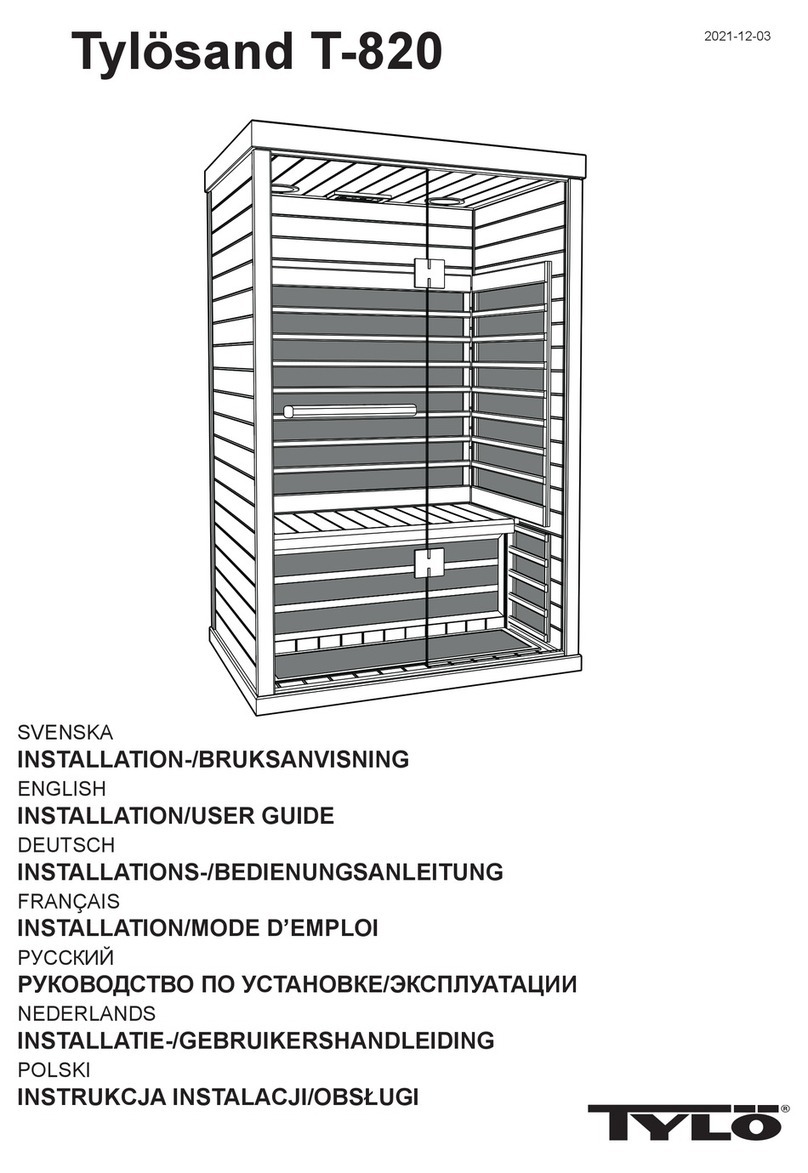
Tylo Prime+ 1210 User manual

Tylo

Tylo Prime+ 1210 User manual

Popular Plumbing Product manuals by other brands

Brizo Odin 88875 Series installation instructions

Brizo

Brizo Odin 88875 Series installation instructions

SUMERAIN S1357CM user manual

SUMERAIN

SUMERAIN S1357CM user manual

Triton ASPIRANTE Installation and operating instructions

Triton

Triton ASPIRANTE Installation and operating instructions

Hans Grohe RainBrain 15840180 Assembly instructions

Hans Grohe

Hans Grohe RainBrain 15840180 Assembly instructions

AMBIANCE BAIN CONCEPT KETTY DUO DUO100 Assembly and Fitting Instructions

AMBIANCE BAIN

AMBIANCE BAIN CONCEPT KETTY DUO DUO100 Assembly and Fitting Instructions

Grohe ATRIO 25 044 instructions

Grohe

Grohe ATRIO 25 044 instructions

Whale Digital Smoothflow Installation guidelines

Whale

Whale Digital Smoothflow Installation guidelines

Kalia Preciso BF1802 installation instructions

Kalia

Kalia Preciso BF1802 installation instructions

Taymor 06-9523SP installation instructions

Taymor

Taymor 06-9523SP installation instructions

Luxart Poydras PO711FMTO installation instructions

Luxart

Luxart Poydras PO711FMTO installation instructions

Helvex Squadra E-929 installation guide

Helvex

Helvex Squadra E-929 installation guide

Grohe Eurodisc 33 334 manual

Grohe

Grohe Eurodisc 33 334 manual

unidrain 8023.0075 installation guide

unidrain

unidrain 8023.0075 installation guide

b-intense Zen Assembly instructions

b-intense

b-intense Zen Assembly instructions

Blanco 1-3/4 Reverse Bowl Undermount 510-882R Specifications

Blanco

Blanco 1-3/4 Reverse Bowl Undermount 510-882R Specifications

ABOUTWATER AF/21 instructions

ABOUTWATER

ABOUTWATER AF/21 instructions

Fantini Rubinetti Aqua Zone C032 instructions

Fantini Rubinetti

Fantini Rubinetti Aqua Zone C032 instructions

Delinia LOA 3276007099621 instruction manual

Delinia

Delinia LOA 3276007099621 instruction manual

manuals.online logo
manuals.online logoBrands
  • About & Mission
  • Contact us
  • Privacy Policy
  • Terms and Conditions

Copyright 2025 Manuals.Online. All Rights Reserved.