UAB NAVITUS LT MCL 5 IP User manual

Controller with internal Quad-band GSM/GPRS/3G modem
MCL 5 IP
User manual
Version 2.0
UAB NAVITUS LT
Lithuania, 2018

2
Document revision history
Version
Date
Revision history
Controller
Firmware version
1.0
2013.03.19
First Issue
1.0
2.0
2015.08.25
Issue with 3G modem
1.0
Disclaimer
UAB NAVITUS LT guarantees that the following documentation is correct and intended for the device
described. The manufacturer has no obligation for guarantee if the documentation is used for any other
device not listed in this documentation. UAB NAVITUS LT has the right to update or alter documentation
without prior notice.

3
Contents
DOCUMENT REVISION HISTORY.................................................................................................................................... 2
SIGNS AND ABBREVIATIONS ......................................................................................................................................... 4
SAFETY INSTRUCTIONS.................................................................................................................................................. 5
AVAILABLE MODIFICATIONS.......................................................................................................................................... 6
1. APPLICATION AND FUNCTIONALITY..................................................................................................................... 7
1.1. GENERAL INFORMATION................................................................................................................................... 7
1.2. SUPPORTED COMMUNICATION PROTOCOLS................................................................................................. 7
1.3. CONFIGURATION................................................................................................................................................. 7
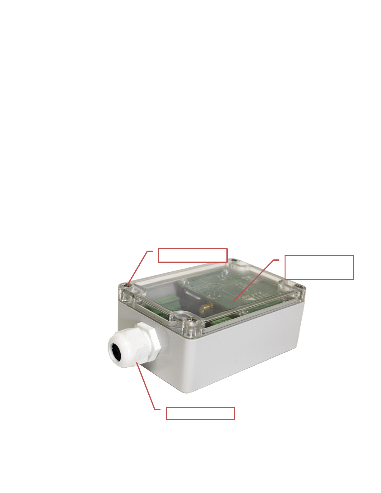
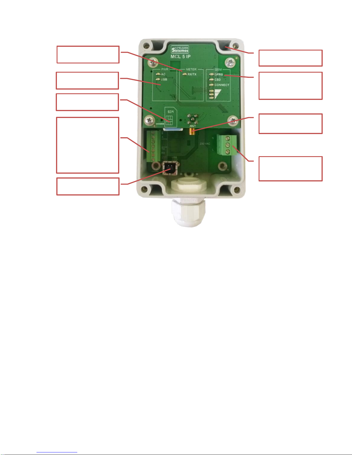
2. PRINCIPAL COMPONENTS OF THE CONTROLLER MCL 5 IP.............................................................................. 9
3. TECHNICAL CHARACTERISTICS.......................................................................................................................... 10
4. INSTALLATION........................................................................................................................................................ 12
4.1. INSTALLATION STEPS:..................................................................................................................................... 12
4.1.1 CONNECTING POWER CABLE TO THE MCL 5 IP............................................................................................... 13
4.2. SOCKETS AND INTERFACES........................................................................................................................... 13
4.3. CONNECTING METER/METERS OR OPTICAL READ-OUT HEAD OVER RS485 .......................................... 14
4.3.1. CONNECTING A METER OVER RS485 ........................................................................................................ 14
4.3.2. CONNECTING AN OPTICAL READ-OUT HEAD OVER RS485 ................................................................... 14
4.4. CONNECTING A METER OR OPTICAL READ-OUT HEAD OVER RS232....................................................... 15
4.4.1. CONNECTING A METER OVER RS232 ........................................................................................................ 15
4.4.2. CONNECTING AN OPTICAL READ-OUT HEAD OVER RS232 ................................................................... 15
4.5. CONNECTING A PC OVER USB PORT FOR PARAMETERIZATION.............................................................. 15
5. LABELLING INFORMATION................................................................................................................................... 16
6. PARAMETERIZATION GUIDE................................................................................................................................. 16
6.1. INITIAL INFORMATION...................................................................................................................................... 16
6.2. PROCEDURE OF LOCAL PARAMETERIZATION............................................................................................. 17
7. PARAMETERIZATION............................................................................................................................................. 21
7.1. SECURITY........................................................................................................................................................... 21
7.2. DEFAULT PASSWORD...................................................................................................................................... 21
7.3. APN..................................................................................................................................................................... 21
7.4. AUTOMATIC REBOOT....................................................................................................................................... 21
7.5. FIRMWARE UPDATE ......................................................................................................................................... 21
7.5.1. AUTOMATIC FIRMWARE UPDATE............................................................................................................... 21
7.5.2. MANUAL FIRMWARE UPDATE .................................................................................................................... 21
7.6. BYTE W. TIMEOUT IN X BYTES........................................................................................................................ 21
8. EVENT LOG............................................................................................................................................................. 21
8.1. EVENT LOG RECORD FORMAT ....................................................................................................................... 21
8.2. LOGGING EVENTS............................................................................................................................................. 21
ANNEX A. CONTROLLER MENU AND CONFIGURATION SETTINGS......................................................................... 23
ANNEX B. USB INSTALLATION GUIDE......................................................................................................................... 27
ANNEX C. MANUFACTURER’S GUARANTEE .............................................................................................................. 32

4
Signs and Abbreviations
AC / DC
Alternating Current / Direct Current
APN
Access Point Name
CSD
Circuit Switched Data
EMC
Electromagnetic Compatibility
GPRS
General Packet Radio Service
GSM
Global System for Mobile communications
ISP
Internet Service Provider
IP
Internet Protocol address
IMEI
International Mobile Equipment Identity
LED
Light Emitting Diode
N/A
Not Available / Not Applicable
PC
Personal Computer
PIN
Personal Identification Number
Rx
Receiver connector
SIM
Subscriber Identity Module
SMA
SubMiniature version A connector
TCP/IP
Transmission Control Protocol/Internet Protocol
Tx
Transmitter connector
VPN
Virtual Private Network
URL
Uniform Resource Locator
USB
Universal Serial Bus

5
Safety Instructions
Please ensure you read and understand the installation instructions entirely before
attempting to install and configure MCL 5 IP.
Always disconnect the mains supply while installing or servicing the communication
interfaces, antenna or changing SIM card.
Only the authorized service persons with adequate qualifications can perform
installation, uninstallation and parameterization of the GSM/GPRS controller MCL 5
IP. National wiring rules should be followed while installing and using the controller.
All equipment interconnected with this product should comply with the requirements
of EN 60950-1:2006 (Personal computer, etc.) or other adequate safety standard
applicable to the equipment (electricity meters).
GSM/GPRS controller should be mounted in restricted access locations. Only
authorised personnel should be able to access this location.
Some parts may remain energized even if the power is disconnected! Do not try to
disassemble internal components. There are no serviceable parts inside.

6
Available Modifications
The controller modification is stated on the controller passport and on the label.
BX.
TX.
X.
X.
Example
B1.
T1.
1.
1.
Data Transfer Rates, Baud
300, 600, 1200, 2400, 4800, 9600, 19200
0
300, 600, 1200, 2400, 4800, 9600, 19200, 38400, 115200
1
Internal Thermometer
Not Present
0
Present
1
Digital Input
Not Present
0
1 channel
1
Analogue Input
Not Present
0
1 channel
1
Table 1. MCL 5 IP modification table

7
1. Application and Functionality
1.1.General Information
MCL 5 IP controller (further referred to as a controller) is used in AMR systems for automated remote data
reading of electricity, heat meters and other electronic devices and data transmission to remote offices.
Device does not store, manipulate or alter meter information.
GSM radio network with CSD/GPRS/3G technology and TRANSPARENT DATA, TCP/IP protocols is used
for data transmission to the management system.
Depending on modification MCL 5 IP can have analogue and digital inputs for auxiliary devices.
1.2.Supported Communication Protocols
Controller supports two-direction data exchange with communication protocols IEC 62056-31,
DLMS/COSEM (all security layers as well) or IEC 62056-21.
1.3.Configuration
RS232 and RS485 electric communication interfaces are used for meter data read-out.
An Optical Read-out Head can be connected to RS485/RS232 in order to read out meter data via the optical
interface (infrared).
Device parameterization can be performed locally via USB and RS232 interfaces or GSM/GPRS.
Controller supports both TCP/IP server and client connection modes.
Controller’s structure and interface locations are indicated below.
Figure 1-1. MCL 5 IP principal external components
Transparent protective
cover
Cover fixing bolts
Cable gland cap

8
Figure 1-2. MCL 5 IP principal internal components
Connectors for meter
and/or Optical Read-
out head/other input
connection with
indicated controller’s
Tx and controller’s Rx
connectors
SIM card slot
AC Power supply
connector
SMA female antenna
socket
GSM mode and signal
strength indicators
Power and USB
indicators
Meter activity
indicators
USB female socket
for PC connection
MCL 5 IP mounting
holes

9
2. Principal Components of the controller MCL 5 IP
The main controller components are listed below:
a) CSD/GSM/GPRS/3G modem is used for modem programming, firmware update, data reading and
parameterization
GSM/GPRS Modem
GSM/GPRS bands
850/900/1800/1900 Mhz
Class of power transmission
Multi-slot class 10, CS1-CS4, Class B
Data Speed
up to 85.6 kb/s
Uplink time slot
2
Antenna Connector type
SMA (50 Ohm)
CSD (Circuit switched data)
Max. 9.6 kb/s user data
3G modem
UMTS / EDGE Bands
850/900/1800/1900/2100 Mhz
Class of power transmission
Multi-slot class 12, MCS1-9, Class B
Data Speed
HSUPA cat 6, up to 5.76 Mb/s UL
HSDPA cat 8, up to 7.2 Mb/s DL
WCDMA PS up to 384 kb/s DL/UL
EDGE multi-slot class 12, up to 236.8 kb/s DL/UL
Table 2-1. Main characteristics of a modem
b) Galvanically non-separated communication interfaces:
USB device: for local modem programming, firmware update, data reading and parameterization;
c) Galvanically separated communication interfaces:
RS232 (TX, RX, GND): used for meter data read-out. Supports only one meter;
RS485 (half duplex): used for meter data read-out. Supports up to 32 electricity meters;
d) АС/DС (90-264), power supply connector;
e) Antenna type SMA socket.
Outer antenna with a magnetic/adhesive base and a 3 to 5 meter long cable (50 Ohm) can be
ordered separately. Antenna can have an optional signal strengthening 0 to 11 dBi.

10
3. Technical Characteristics
Power supply input voltage range (50/60Hz)
90 ... 264 V
Power consumption:
a. maximum in transmission mode:
b. average in dutymode:
< 10 VA
< 5 VA
Meter to controller net baud rate*, Baud
300... 115200
PC to controller net baud rate via USB device interface, 8N1
bits, Baud
115200
Number of meters connected to RS485 interface
1… 32
Number of meters connected via optical Read-out Head
1
Number of meters connected to RS232 interface
1
Analogue input interface*, 12 bit, 0-48V
1
Digital input interface, 100Hz*
1
Number of simultaneous communication sessions GSM/CSD/GPRS
6
Internal thermometer measurement range*,оС
-40 ... +100**
Work temperature range, оС
-20 ... +60
Storage temperature range, оС
-40 ... +70
Relative humidity, % without condensate
20 ... 90
Plastic Materials, safety of flammability
ABS
Internal Protection Marking
IP-64
Immunity to surge pulses from AC 230V
6 kV (1,2/50 μs), 50 Ohm
Dimensions, mm
150x80x50
RoHS
Compliant
Standards of electromagnetic interference and isolation
Compliant
IEC/TS 61000-6-5 certification*
Compliant
* Depends on device modification
** Elgama Sistemos Ltd guarantees that internal thermometer will be fullyfunctioning in the range of the device
work temperature as per above
Table 3-1. MCL 5 IP controller technical characteristics

11
LED
LED meaning, when active
PWR: Interface activity
AC
AC power is on
USB
USB host is connected
METER: Meter Interface activity
RX/TX
Data transfer; active interface
GSM: Operation and received signal strength indication
GPRS
Registered to GSM/GPRS network (call
waiting)
CSD
Registered to CSD network
CONNECT
GPRS/CSD data session active;
(connection established)
GSM: Signal level range indication*
LED –top
Indicates signal strength -113 to -82
dBm or less
LED –middle
Indicates signal strength -81 to -70
dBm
LED –bottom
Indicates signal strength -69 to -51
dBm or more
*Default values indicated. Signal indication level can be changed in the Menu
Table 3-2. MCL 5IP controller indicators and description
AC
PWR
METER
USB
GSM
RX/TX
GPRS
CSD
CONNECT

12
4. Installation
Important: Before proceeding, please ensure the device will remain clean and dry
during the installation and no liquid or other substance will remain inside as that could
severely affect device performance and warranty.
Important: Allowed bolt head diameter can be from 6 to 7,5 mm and the body diameter
from 3,4 to 4 mm. A set of mounting bolts are supplied with the controller
Important: PIN code of a SIM card must be disabled prior the installation
4.1.Installation Steps:
a) Unscrew 4 bolts at each corner holding the transparent cover and take the cover off
b) Controller can be mounted on a wall using four mounting holes (indicated below) at the corners of the
device. Position the device vertically so that the face of the device is clearly visible for led indication and
connection interfaces are easily accessible
c) Place the controller in the desired location and screw in the mounting bolts through the mounting holes.
d) Insert the SIM card firmly into the dedicated slot
e) Gently place the SIM card in a slot marked “SIM” on the main face until it reaches the back of the slot.
Check if the SIM card is secured inside. Connect the controller to the voltage network.
f) Unscrew the cable gland cap and pass the external antenna cable, meter cable and/or optical read-out
head cable and other required cables through the cap first
g) Connect required meter or optical read-out head device to the required connectors as per paragraph 4.1
and manufacturer’s instructions

13
h) Make sure that after controller is connected to the power source and is fully operational
i) Re-apply the cover and secure it with the 4 screws to ensure the device remains water tight
j) Re-apply cable gland cap and secure it firmly
4.1.1 Connecting power cable to the MCL 5 IP
On the right of the controller there is the
power source connector. The controller
must be connected to the 230 VAC power
supply as shown in the figure. Connect one
wire to the MCL 5 IP N(null) socket and the
other wire to the L (phase) socket.
4.2. Sockets and Interfaces
Controller sockets are shown in a table below:
INTERFACE
CONNECTORS
DESIGNATION
RS485
B
A
Used for connecting up to 32 meters
Optical Read-
out Head
+5V
B/TX
A/RX
GND
Used for connecting an Optical Read-out head. Optical Read-Out
head is connected by using the same RS485 or RS232
connectors that are used for connecting a meter
RS232
TX
RX
GND
Used for a single meter connection
USB
USB female socket
Used for controller configuration via PC
Antenna
Connection
SMA female
socket
Used for connecting an internal/external GSM/GPRS antenna
Table 4.2-1. MCL 5IP controller indicators and description
Figure 4.2-1. Controller sockets
Null
Phase

14
4.3.Connecting Meter/Meters or Optical Read-Out Head Over RS485
4.3.1. Connecting a Meter Over RS485
In order to connect a meter, please connect controller’s “A”connector with a meter’s “A” and be “B”
connector with its “B” socket of RS485 interface (see Figure 4.2-1). If there is more than one meter to be
connected the parallel method must be used as indicated below:
4.3.2. Connecting an Optical Read-out Head Over RS485
Optical Read-out Head allows connecting a meter with a controller by using infrared technology. For the best
use it is recommended to use UAB NAVITUS LT Optical Read-out Head OKK (or other manufacturers’
product) compatible with the IEC 62056-21 standard.
The Optical Read-out Head has four connection wires in total where its two wires should be connected to the
same RS485 interface and remaining two wires to the controller’s +5V (5 Volts) and GND (ground)
connectors found nearby according to the optical read-out head specifications and manufacturer’s manuals.
*Colors may differ
MCL 5 IP
socket
Optical Head
wire color*
Optical Head
wire value
B
White
B
A
Green
A
GND
BLACK
-
5V
RED
+
TX
RX
GND
Figure 4.3.1-1. Meter connection to RS485 interface
123 kWh
125
kWh
124 kWh
MCL 5 IP
RS485
A
RS48
5
B
A
A
RS48
5
B
B
A
RS48
5
B
Meters 1 .. 32, parallel connection method

15
4.4.Connecting A Meter Or Optical Read-out Head Over RS232
4.4.1. Connecting a Meter Over RS232
A meter can be connected using RS232 interface. RS232 supports only one meter connection using Tx, Rx
and GND connectors. Controller’s Tx and Rx connectors are indicated on the board.
4.4.2. Connecting an Optical Read-out Head Over RS232
Optical Read-out Head allows connecting a meter with a controller by using infrared technology. For the best
it is recommended to use UAB NAVITUS LT Optical Read-out Head OKK (or other manufacturers’ product)
compatible with the IEC 62056-21 standard.
UAB NAVITUS LT OKK Optical Read-out Head OKK for RS232 is connected in the following way:
Controller’s Rx connector goes to OKK Tx connector and controller’s Tx connector goes to OKK Rx
connector.
Other manufacturers might have a different setup.
4.5.Connecting a PC over USB Port For Parameterization
Important: Controller’s USB connection can be used only after transparent cover is
taken off.
Important: When using an USB cable, ensure the cable is unplugged each time
before the restart of the device and plugged back again if required
Connect a computer to the controller with a USB cable and follow the parameterization steps as in
paragraphs 6 and 7.
MCL 5 IP
socket
Optical Head
wire color
Optical Head
wire value
B
A
GND
5V
Red
+
TX
White
RX
RX
Green
TX
GND
Black
-

16
5. Labelling Information
Principal controller information is marked on a label.
Label explanation:
LED indicator position
Controller name
Power supply input and consumption characteristics
Unique identification number (S/N)
6. Parameterization Guide
6.1.Initial Information
MCL 5 IP controller using either CSD or GPRS technology transmits the data of measurement equipment
(meters). There is an internal modem with a SIM card socket.
Connect the controller to the computer‘s COM or USB (depending on connection) port to start the setup.
Connect the antenna before switching the controller on. It is not necessary to insert a SIM card for
parameterization. If there is an ongoing data readout, it must be interrupted before parameterization. If the
controller was just turned on wait about 30 seconds before connecting.
Important: Parameterization may vary depending on connection interface type, device
version, administrator’s PC operating system region and version. Therefore figures and
menus given below may differ from actual due to software updates and upgrades.
Important: It is required to disable PIN request on a SIM card, before inserting it in the
controller’s SIM socket
Important: Controller’s USB connection can be used only after transparent cover is
taken off.
Important: When using an USB cable, ensure the cable is unplugged each time before
the restart of the device and plugged back again if required
Do not connect parameterization cables and start the parameterization until 30 seconds
are elapsed after controller was switched on.
The USB cable connected to the controller firstly must be installed to the computer as
virtual COM port. The installation guide is described in the Annex B: USB installation
guide.

17
6.2.Procedure of Local Parameterization
Access to the controller can be protected by a password. Two levels of users are possible: admin login and
user login. Each login has separate menus and control functions. Parameterization can be handled using
HyperTerminal (Figure 6.2-1, Figure 6.2-2) or other software allowing connecting MCL via device’s USB
interface. The settings of a COM port for parameterization are independent from the settings for the data
readout and can be set as follows: 115200 bps, parity - none, 8 data bits and flow control - none.
After parameterization user must restart the controller's using the reset function in the menu.
Important! To load or re-load controller’s menu press button ESC (on keyboard)
3 times.
Enter a name for the new connection (Figure 6.2-1)
Figure 6.2-1
Select a port MCL is connected to (Figure 6.2-2)
Figure 6.2-2
After pressing OK in the COM Properties window (figure 6.2-3), the settings are set to Auto detect by default
(figure 6.2-4).

18
Figure 6.2-3 Select port settings
Figure 6.2-4
To change the values:
1. Press Disconnect button as shown on figure 6.2-5 (arrow 1);
2. Press Properties button as shown on figure 6.2-5 (arrow 2);

19
Figure 6.2-5
3. Press Configure button as shown on figure 6.2-6 (arrow 3);
4. Press OK button as shown on figure 6.2-6 (arrow 4);
Figure 6.2-6
115200

20
5. Important. Ensure that other settings of the connection are set as shown on figures 6.2-7;
Figure 6.2-7
The settings should change to 115200 8-N-1 as shown on figure 6.2-8
Figure 6.2-8
Important! To load or re-load controller’s menu press button ESC (on keyboard)
3 times.
Table of contents
Popular Controllers manuals by other brands

ETC
ETC ArcSystem Pro D4 Series installation guide

Newport Electronics
Newport Electronics INFINITY Series manual

Honeywell
Honeywell dcp100t Operator's manual

DMP Electronics
DMP Electronics X1 COMPLIANCE GUIDE

THORLABS
THORLABS MDT693B user guide

Truma
Truma SecuMotion Operating instructions & installation instructions