uAvionix Ping1090 Manual

UAV-1000711-001
ECCN 7A994 Page 1 | 24
Ping1090
User and Installation Guide

UAV-1000711-001
ECCN 7A994 Page 2 | 24
© 2017 uAvionix Corporation. All rights reserved.
uAvionix Corporation
380 Portage Ave.
Palo Alto, CA 94306
http://www.uavionix.com
support@uavionix.com
Except as expressly provided herein, no part of this guide may be
reproduced, transmitted, disseminated, downloaded or stored in any
storage medium, for any purpose without the express written permission of
uAvionix. uAvionix grants permissions to download a single copy of this
guide onto an electronic storage medium to be viewed for personal use,
provided that the complete text of this copyright notice is retained.
Unauthorized commercial distribution of this manual or any revision hereto
is strictly prohibited.
uAvionix®is a registered trademark of uAvionix Corporation, and may not
be used without express permission of uAvionix.

UAV-1000711-001
ECCN 7A994 Page 3 | 24
1 Revision History
Revision
Date
Comments
A
4/26/2017
Initial release
B
5/25/2017
Export Control Statement

UAV-1000711-001
ECCN 7A994 Page 4 | 24
2 Warnings / Disclaimers
All device operational procedures must be learned on the ground.
uAvionix is not liable for damages arising from the use or misuse of this
product.
These items are controlled by the U.S. Government and authorized for
export only to the country of ultimate destination for use by the ultimate
consignee or end-user(s) herein identified. They may not be resold,
transferred, or otherwise disposed of, to any other country or to any person
other than the authorized ultimate consignee or end-user(s), either in their
original form or after being incorporated into other items, without first
obtaining approval from the U.S. government or as otherwise authorized by
U.S. law and regulations.
3 Limited Warranty
uAvionix products are warranted to be free from defects in material and
workmanship for one year from the installation in the aircraft. For the
duration of the warranty period, uAvionix, at its sole option, will repair or
replace any product which fails under normal use. Such repairs or
replacement will be made at no charge to the customer for parts or labor,
provided that the customer shall be responsible for any transportation cost.
This warranty does not apply to cosmetic damage, consumable parts,
damage caused by accident, abuse, misuse, water, fire or flood, damage
caused by unauthorized servicing, or product that has been modified or
altered.
IN NO EVENT, SHALL UAVIONIX BE LIABLE FOR ANY INCIDENTAL,
SPECIAL, INDIRECT OR CONSEQUENTIAL DAMAGES, WHETHER
RESULTING FROM THE USE, MISUSE OR INABILITY TO USE THE
PRODUCT OR FROM DEFECTS IN THE PRODUCT. SOME STATES DO
NOT ALLOW THE EXCLUSION OF INCIDENTAL OR CONSEQUENTIAL
DAMAGES, SO THE ABOVE LIMITATIONS MAY NOT APPLY TO YOU.
UAV-1000711-001
ECCN 7A994 Page 5 | 24
Warranty Service
Warranty repair service shall be provided directly by uAvionix.

UAV-1000711-001
ECCN 7A994 Page 6 | 24
4 Contents

UAV-1000711-001
ECCN 7A994 Page 7 | 24
5 Introduction
5.1 Description
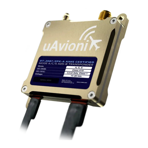
PINGTM is the world’s smallest, lightest and most affordable full range,
dual link ADS-B transceiver. At just 20 grams, it implements ‘Sense and
Avoid’ for Drone operations in the national airspace. ADS-B-In on both
1090ES and 978UAT. ADS-B-Out on 1090MHz. No deviations from the
Minimum Performance Standards of DO-260B Class A0 apart from
minimum transmit power.

UAV-1000711-001
ECCN 7A994 Page 8 | 24
5.2 Interfaces
The Ping1090 has a single SMA antenna connection, a 6-pin Host interface
and a 4-pin FYXnav GPS interface.
Host Interface
Interface
Specification
Protocol
AutoPilot
57600bps
MavLink
Navigation
115200bps
MavLink

UAV-1000711-001
ECCN 7A994 Page 9 | 24
5.3 Software and Airborne Electronic Hardware
Configuration.
Part
Part Number
Revision
Software
UAV-1000704-001
A
Airborne Electronic Hardware
UAV-1000706-001
A
5.4 Supplied Accessories
Part
Part Number
Revision
Ping1090
UAV-1000706-001
A
Power Cable
UAV-1000792-001
A
PixHawk 1 Cable
UAV-1000793-001
A
PixHawk 2 Cable
UAV-1000780-001
A
FYXnav Cable
UAV-1000768-001
A
WiFi Programmer
UAV-1000706-001
A
Dipole Antenna
UAV-1000653-001
A
Ping1090 User Manual
UAV-1000711-001
A

UAV-1000711-001
ECCN 7A994 Page 10 | 24
6 Technical Specifications
Specification
Characteristics
Compliance
Class A0 DO-260B
CAP 1391 Basic EC Device
Software
RTCA DO-178B Level C
Hardware
RTCA DO-254 Level C
Power
Requirements
6-14V. Typical 1W On/Alt, 0.1W Standby.
Altitude
35,000ft
Operating
Temperature
-45°C to +70°C
Humidity
Tested to Category DO-160G Category B2
Transmit
Frequency
1090MHz ±1MHz
DO-260B
Messages
ADS-B DF18
Transmit Power
25W nominal; 20W minimum at antenna after
allowing for 0.5dB connector losses and 1.5dB
cable losses.
Transmitter
Modulation
6M75 V1D
Pulse Amplitude Modulation
Receiver
Frequency
1090MHz
Receiver
Sensitivity
-74dBm ±3dB
Weight
25 grams
Height
14mm
Length
41mm
Width
25.4mm

UAV-1000711-001
ECCN 7A994 Page 11 | 24
7 Equipment Limitations
7.1 Installation
7.1.1 Modifications and Use Outside of Intended Scope
This device has been designed and tested to conform to all applicable
standards in the original form and when configured with the components
shipped with the device. It is not permissible to modify the device, use the
device for any use outside of the intended scope, or use the device with
any antenna other than the one shipped with the device.
7.1.2 Deviations
There are no deviations from the MPS of DO-260B Class A0 Device.
7.1.3 Configurable Options
Accessing or altering configurable options not intended to be operated may
cause pilot distraction.
7.1.4 Approvals
Approvals do not cover adaptations to the aircraft necessary to
accommodate ancillary equipment such as power provisions, mounting
devices or external antennas; such items must still be approved under
existing minor modification/change processes applicable to the aircraft.
This device meets the minimum performance and quality control standards
required by a technical standard order (TSO). Installation of this device
requires separate approval.

UAV-1000711-001
ECCN 7A994 Page 12 | 24
8 Equipment Installation
This section describes the installation of Ping1090 and related accessories
in the aircraft, including mounting, wiring, and connections.
8.1 Unpacking and Inspecting
Carefully unpack the device and make a visual inspection of the unit for
evidence of any damage incurred during shipment. If the unit is damaged,
notify the shipping company to file a claim for the damage. To justify your
claim, save the original shipping container and all packing materials.
8.2 Mounting
The Ping1090 is designed to be mounted in any convenient location in the
cockpit, the cabin, or an avionics bay.
The following installation procedure should be followed, remembering to
allow adequate space for installation of cables and connectors.
•Select a position in the aircraft that is not too close to any high
external heat source. The Ping1090 is not a significant heat source
itself and does not need to be kept away from other devices for this
reason.
•Avoid sharp bends and placing the cables too near to the aircraft
control cables.

UAV-1000711-001
ECCN 7A994 Page 13 | 24
8.3 Connections
Whenever power is supplied to the transponder, a 50ohm load
must be provided to the SMA connection. You can use the
supplied antenna or a commercially available 50ohm load.
!

UAV-1000711-001
ECCN 7A994 Page 14 | 24
8.4 Wiring Diagram
Navigation Source Interface
Pin
Type
1
Input
UTC
2
Input
RXD
MavLink
3
Output
TXD
GDL90
4
Power
5V
5
Ground
Ground
Mating Connector: JST ZHR-5
Pins: SZH-002T-P0.5 Indicators
LED
ON
FLASHING
BLUE
1090ES Traffic
GREEN
UAT Traffic
RED
FAULT
Testing
Power Interface
Pin
Type
1
Power
6-14V
2
Ground
Mating Connector: Molex 0436450200
Pins: 0462350001
Data Interface
Pin
Type
1
Input
RXD/SDA
MavLink
2
Output
TXD/SCL
MavLink
3
Power
5V
4
Ground
Mating Connector: JST ZHR-4
Pins: SZH-002T-P0.5

UAV-1000711-001
ECCN 7A994 Page 15 | 24
8.5 Cooling Requirements
Ping1090 is designed to meet all applicable TSO requirements without
forced-air cooling.
Attention should, however, be given to the incorporation of cooling
provisions to limit the maximum operating temperature if Ping1090 is
installed in close proximity to other Avionics. The reliability of equipment
operating in close proximity in an avionics bay can be degraded if adequate
cooling is not provided.
8.6 Wiring Considerations
The Ping1090 was designed and tested using unshielded, untwisted wiring.
There may, however, be technical benefits of improved electromagnetic
emissions and susceptibility to and from the transponder system. Use of
twisted wire can reduce interference and break-through on adjacent audio
wiring if it is not possible to route them separately.
The distance between the Ping1090 and the power adapter is limited by the
impedance of the wire between them. The Ping1090 is powered directly
from aircraft power, and, therefore, the acceptable voltage drop in the
power line is what limits the distance.
The Ping1090 needs an impedance of less than 0.5ohm in the power line
for satisfactory operation. The following table gives guidance for typical
aircraft hook-up wire. Note that different brands may vary –check your
supplier for details.
Gauge
ohm/km
Length for 0.5ohm
20 AWG
35
14.2m
22 AWG
64
7.8m
24 AWG
99
5.0m
An alternative to a harness built from individual wires, particularly for a long
cable run, is to use a multi-core cable. Aviation grade cables with 6 or more
cores are often more expensive than individual wires, and, therefore, are
not generally a good choice. For aircraft where those situations do not

UAV-1000711-001
ECCN 7A994 Page 16 | 24
apply, an attractive alternative solution may be to use 3 or 4 pair data
cable.
Please note that not all data cable is suitable for this application. Cables
with solid cores should not be used. Cables should be selected based on
the wear characteristics of their insulation material, including temperature
rating, resistance to solvents and oils, and flammability. Most inexpensive
commercial data cables have poor flammability properties.
8.7 Antenna Installation
8.7.1 Supplied Dipole Antenna
The following considerations should be taken into account when siting the
antenna.
•The antenna should be well removed from any projections, the
engine(s) and propeller(s). It should also be well removed from
landing gear doors, access doors or other openings which will break
the ground plane for the antenna.
•The antenna should be mounted in a vertical position when the
aircraft is in level flight.
•Avoid mounting the antenna within 1 meter of the ADF sense antenna
or any COMM antenna and 2 meters from the transponder to the
DME antenna.
•Where practical, plan the antenna location to keep the cable lengths
as short as possible and avoid sharp bends in the cable to minimize
the VSWR.
Electrical connection to the antenna should be protected to avoid loss of
efficiency due to exposure to liquids and moisture. All Antenna feeders
shall be installed in such a way that a minimum of RF energy is radiated
inside the aircraft.
8.7.2 Conventional OEM Monopole Antenna
The antenna should be installed according to the manufacturer’s
instructions.

UAV-1000711-001
ECCN 7A994 Page 17 | 24
The following considerations should be taken into account when siting the
antenna.
•The antenna should be well removed from any projections, the
engine(s) and propeller(s). It should also be well removed from
landing gear doors, access doors or other openings which will break
the ground plane for the antenna.
•The antenna should be mounted on the bottom surface of the aircraft
and in a vertical position when the aircraft is in level flight.
•Avoid mounting the antenna within 1 meter of the ADF sense antenna
or any COMM antenna and 2 meters from the transponder to the
DME antenna.
•Where practical, plan the antenna location to keep the cable lengths
as short as possible and avoid sharp bends in the cable to minimize
the VSWR.
Electrical connection to the antenna should be protected to avoid loss of
efficiency due to exposure to liquids and moisture. All antenna feeders shall
be installed in such a way that a minimum of RF energy is radiated inside
the aircraft.
When a conventional aircraft monopole antenna is used it relies on a
ground plane for correct behavior. For ideal performance, the ground plane
should be large relative to the wavelength of the transmission, which is
275mm. In a metal, skinned aircraft this is usually easily accomplish, but is
more difficult in a composite or fabric skinned aircraft. In these cases, a
metallic ground plane should be fabricated and fitted under the antenna.
The ground plane should be as large as you can sensibly make it. Because
it is a function of the wavelength of the transmission, the smallest practical
ground plane for a transponder is a approx. 120mm per side; as the size
increases, the performance improves, until the ground plane is approx.
700mm on each side. Anything much larger than that size is unlikely to
result in significant further improvement.
The thickness of the material used to construct the ground plane is not
critical, providing it is sufficiently conductive. A variety of proprietary mesh
and grid solutions are available. Heavyweight cooking foil meets the
technical requirement, but obviously needs to be properly supported.

UAV-1000711-001
ECCN 7A994 Page 18 | 24
8.7.3 Antenna Cable
The Ping1090 is designed to meet Class 1 requirements with an allowance
of 2dB for loss in connectors and cable used to connect it to the antenna.
Excessive loss will degrade both transmitter output power and receiver
sensitivity.
Allowing for 0.25dB loss for the connector at each end of the antenna cable
assembly leaves an allowance of 1.5dB maximum loss for the cable itself.
An acceptable cable:
•has less than 1.5dB loss for the run length needed,
•has a characteristic impedance of 50ohms,
•has double braid screens or has foil and braid screen.
Once the cable run length is known, a cable type with low enough loss per
meter that meets the above requirements can be chosen. Longer runs
require lower loss cable.
The following table is a guide to the maximum usable lengths of some
common cable types. Actual cable loss varies between manufacturers.
There are many variants, and the table is based on typical data. Use it as a
guide only and refer to the manufacturer’s data sheet for your specific
chosen cable for accurate values.
Length
Insertion
Loss
MIL-C 17
Specialists
SSB
Electronic
(meters)
(dB/m)
2.54
0.59
M17/128
2.54
0.59
RG400
3.16
0.47
3C142B
3.81
0.39
RG304
4.5
0.33
Aircell 5
5.25
0.29
RG393
311601
6.42
0.23
311501
6.81
0.18
Aircell 7
8.22
0.18
311201

UAV-1000711-001
ECCN 7A994 Page 19 | 24
12.59
0.12
3108801
When routing the cable:
•Route the cable away from sources of heat
•Route the cable wiring away from potential interference sources such
as ignition wiring, 400Hz generators, fluorescent lighting and electric
motors
•Allow a minimum separation of 300mm from an ADF antenna cable
•Keep the cable run as short as possible
•Avoid routing the cable around tight bends
•Avoid kinking the cable, even temporarily, during installation
•Secure the cable so that it cannot interfere with other systems

UAV-1000711-001
ECCN 7A994 Page 20 | 24
9 Configuration
The transponder system should be configured during initial system
installation by a qualified technician. The configuration items list below
should be used to document the system installation for future reference.
Configuration Item
Default
Setting
ICAO Number
0x000000
VFR Squawk Code
1200
Callsign
“SELF “
Aircraft Maximum Speed
Not Available
Aircraft Category
UAV (14)
ADS-B RX Capability
UAT RX
NO
ES1090 RX
NO
Configuration Items List
9.1 ICAO Number
The ICAO address is a 24-bit number issued to the aircraft by the
registration authority of the aircraft. These addresses are usually written as
a 6-digit hexadecimal number, although you may also encounter one
written as an 8-digit octal number. The FYXnav understands the
hexadecimal format. An octal number must be converted to hexadecimal
format before entering.
9.2 VFR Squawk Code
VFR squawk (Mode 3/A) code is a pre-programmed default code when the
pilot is flying VFR and not in contact with ATC. In the USA, the VFR
squawk code is 1200 and in most parts of Europe the VFR squawk code is
7000.
9.3 Callsign
The callsign (aka VFR Flight ID) is an 8 character code that corresponds to
the tail number of the aircraft. (0-9, A-Z).
9.4 Aircraft Maximum Speed
Other manuals for Ping1090
1
This manual suits for next models
1
Table of contents
Other uAvionix Transceiver manuals

uAvionix
uAvionix SkyEcho ATT-20B User manual

uAvionix
uAvionix SkyEcho User manual

uAvionix
uAvionix SkyEcho 2 User manual

uAvionix
uAvionix Ping1090i User manual

uAvionix
uAvionix SkyEcho 2 User manual

uAvionix
uAvionix ping2020i User manual

uAvionix
uAvionix echo User manual

uAvionix
uAvionix ping2020i User manual

uAvionix
uAvionix PING2020 User manual

uAvionix
uAvionix Ping1090 User manual