Ublox EVK-R41Z User manual

EVK-R41Z
Evaluation kit for R41Z modules
User guide
Abstract
This document describes how to set up the EVK-R41Z evaluation kit
to evaluate R41Z series
modules. It also describes the different options for debugging and the development capabilities
included in the evaluation board.
www.u-blox.com
UBX-19033357 - R03

EVK-R41Z - User guide
UBX-19033357 - R03 Page 2 of 23
Document information
Title EVK-R41Z
Subtitle Evaluation kit for R41Z modules
Document type User guide
Document number UBX-19033357
Revision and date R03 5-Nov-2019
Disclosure restriction
This document applies to the following products:
Product name Type number
R41Z-Eval R41Z-Eval-00
u-blox or third parties may hold intellectual property rights in the products, names, logos and designs included in this
document. Copying, reproduction, modification or disclosure to third parties of this document or any part thereof is only
permitted with the express written permission of u
-blox.
The information contained herein is provided “as is” and u
-blox assumes no liability for its use. No warranty, either express or
implied, is given, including but not limited
to, with respect to the accuracy, correctness, reliability and fitness for a particular
purpose of the information. This document may be revised by u
-blox at any time without notice. For the most recent
documents, visit www.u
-blox.com.
Copyright © u
-blox AG.

EVK-R41Z - User guide
UBX-19033357 - R03 Page 3 of 23
Contents
Document information................................................................................................................................2
Contents ..........................................................................................................................................................3
Product description ..............................................................................................................................4
1.1 Key features ................................................................................................................................................. 4
1.2 Kit includes ...................................................................................................................................................5
1.3 Development tools ...................................................................................................................................... 5
Hardware description...........................................................................................................................6
2.1 Power ............................................................................................................................................................. 6
2.2 R41Z power modes..................................................................................................................................... 7
2.2.1 Power configuration switch .............................................................................................................. 8
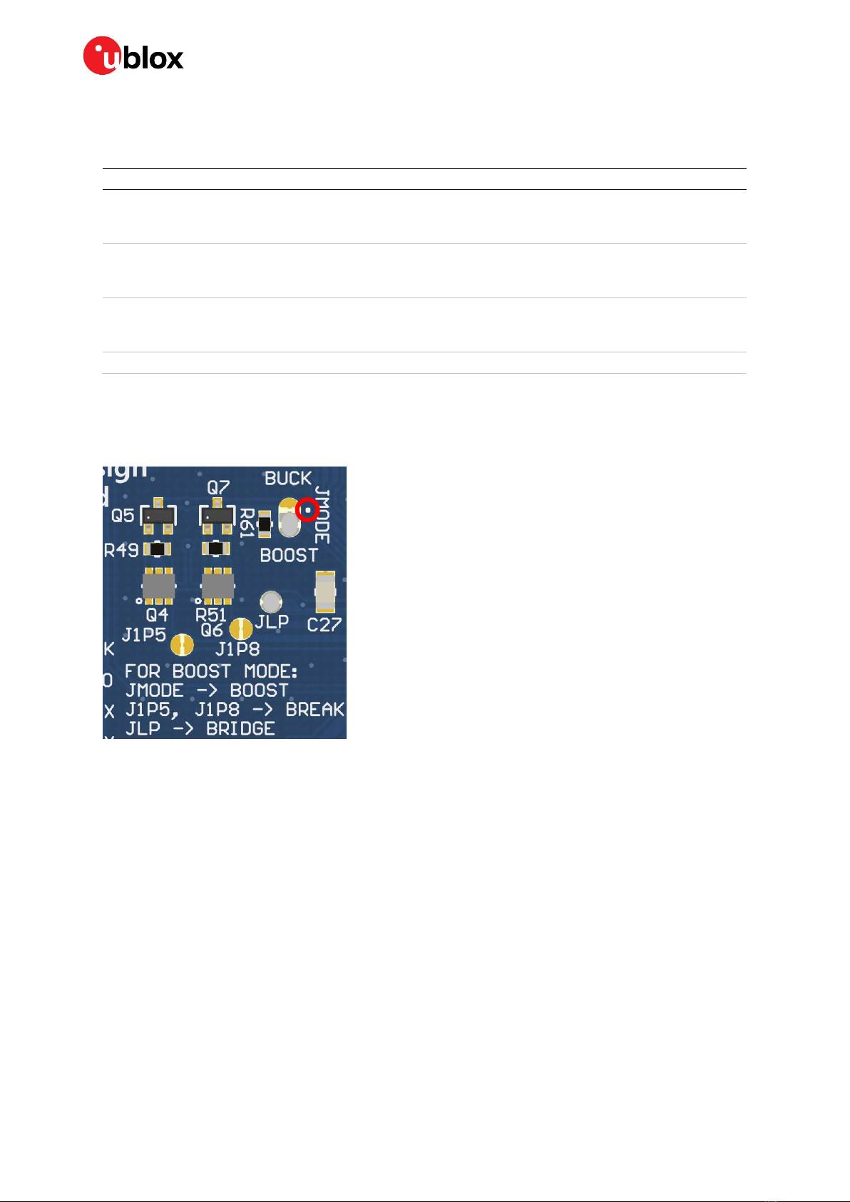
2.2.2 DC-DC mode selection ....................................................................................................................... 8
2.2.3 Measuring power consumption ....................................................................................................... 9
2.3 Debug interface .........................................................................................................................................10
2.3.1 OpenSDA interface...........................................................................................................................10
2.3.2 Reset button......................................................................................................................................10
2.3.3 External debug header.....................................................................................................................11
2.4 Peripherals..................................................................................................................................................11
2.4.1 Expansion headers ...........................................................................................................................12
2.4.2 IR LED Provision ................................................................................................................................12
2.4.3 User LEDs...........................................................................................................................................13
2.4.4 Thermistor .........................................................................................................................................13
2.4.5 User buttons ......................................................................................................................................13
2.4.6 SPI flash..............................................................................................................................................14
2.4.7 I2C acceleration/magnetometer sensor ......................................................................................14
2.5 R41Z module..............................................................................................................................................15
2.5.1 32.768 kHz oscillator .......................................................................................................................15
Setting up the evaluation board.................................................................................................... 16
3.1 Set up the tool chain.................................................................................................................................16
3.2 Try an example...........................................................................................................................................17
Related documents ................................................................................................................................... 22
Revision history.......................................................................................................................................... 22
Contact.......................................................................................................................................................... 23

EVK-R41Z - User guide
UBX-19033357 - R03 Product description Page 4 of 23
Product description
The R41Z evaluation kit allows for stand-alone use of the R41Z module featuring the NXP
MKW41Z RF System on Chip (SoC).
This guide provides setup instructions for starting development and describes the hardware
functionality of the R41Z evaluation kit that can facilitate development of your project.
The R41Z evaluation kit provides a great starting point for almost any Bluetooth low energy,
Thread, or Zigbee project. All the features of the R41Z module are easily accessed from the
evaluation board. A simple USB connection provides power and OpenSDA V2.1 based
debugging. Four user buttons (two conventional and two capacitive) are available, as well as
an RGB LED, reset button, combination acceleration/magnetometer sensor, and an external
4 Mbit flash module. Arduino form factor headers provide access to 16 GPIO and 6 analog
inputs. This allows for easy use of the many existing Arduino shields. Current sense resistors
allow for measuring current into the R41Z module and into the shield.
1.1 Key features
•R41Z Bluetooth low energy and IEEE 802.15.4 module
•On-board programming and debug (OpenSDA v2.1)
•Virtual COM port over USB
•Pin-for-pin compatible with projects created for the NXP FRDM-KW41Z board
•Buttons and LEDs for user interaction
•3-axis combination accelerometer and magnetometer, I2C interface
•4 Mbit Flash, SPI interface
•Provision for IR LED
•32.768 kHz crystal
•CR2032 battery holder
•Supports all DC-DC modes of the R41Z module
•Adjustable output regulator simplifies development
Figure 1: EVK-R41Z evaluation board (Top view)

EVK-R41Z - User guide
UBX-19033357 - R03 Product description Page 5 of 23
1.2 Kit includes
R41Z evaluation kit includes:
•R41Z evaluation board
•Micro-USB cable
•Quick start guide
1.3 Development tools
The tools listed below will aid in development with the R41Z modules. Not all tools will be
required depending on which software suite is used.
Tool Description
MCUXpresso IDE An easy-to-use integrated development environment (IDE) for creating, building,
debugging, and optimizing your application.
MCUXpresso SDK
An open source software development kit (SDK) built specifically for your processor
and evaluation board selections.
MCUXpresso Config Tools A comprehensive suite of system configuration tools, including pins, clocks,
Peripherals, and more.
NXP IoT Toolbox IoT Toolbox is an all-in-one application capable of demonstrating NXP’s Bluetooth®
LE, Zigbee and Thread capabilities through the implementation of Bluetooth® LE
and custom proprietary profiles, allowing the interaction with different
smartphones.
Table 1: Useful tools

EVK-R41Z - User guide
UBX-19033357 - R03 Hardware description Page 6 of 23
Hardware description
Design files for the R41Z evaluation kit can be obtained from your u-blox sales
representative.
2.1 Power
The R41Z evaluation board has three possible power sources: USB, a CR2032 coin cell, and a
2.54 mm through-hole connector. These sources are connected through protection diodes to
prevent reverse voltage to any supply. These allows for more than one source to be connected
at a time. For example, a coil cell battery may remain connected to the board while the board
is being debugged with the USB source connected. However, since the diodes do cause
approximately a 0.3 V drop in source voltage, there is the option to bypass the diodes via solder
jumpers.
☞Care should be taken to not damage the supplies or evaluation board when the protection
is by-passed.
If necessary, the LDO regulator can be disabled in order to allow for USB based debugging while
powering the R41Z from either an external source or a coil cell. Since the R41Z can accept a
wide range of power options, the LDO regulator can be adjusted to simulate some sources. For
details on these options, see the power configuration switch section, 2.2.1.
Figure
2: Evaluation board layout
Accelerometer /
Magnetometer Sensor
SPI Flash
Module
IR-LED
Provision
RGB and Blue
User LEDs
Thermistor
External
Debugger
Header
Peripheral
Current
Measurement
Header
R41Z Module
Power
Configuration
Jumpers
User Button2
User Button5
User Button3
User Button4
Breakout
Headers
OpenSDA
Debug
Interface
Reset Button
USB Power
Regulator
Power
Switch
Power
Protection
Diodes
Ext. Power
Micro-USB
for Power
and Debug
Board Current
Measurement
Header
Power
Configuration
Switch
Breakout
Headers
32.768 kHz

EVK-R41Z - User guide
UBX-19033357 - R03 Hardware description Page 7 of 23
Figure 3: Schematic: Power supply
2.2 R41Z power modes
The R41Z module contains a DC-DC converter that allows it to operate in a variety of power
environments. The R41Z evaluation board supports all these operating modes, which are
summarized below:
Mode Input voltage Output voltage Usage notes
Bypass 1.71 V – 3.6 V N/A DC-DC Converter is bypassed: Input voltage directly supplies all
internal module power rails. Suitable for larger or non-battery powered
applications that have steady, regulated 3.3 V or 1.8 V power rails that
power multiple devices. Since the DC-DC converter is bypassed in this
mode, the R41Z cannot provide regulated power to other devices.
Buck 1.8 V – 4.2 V 1.8 V – 3.0 V 1DC-DC Converter operates in buck mode. Internal power rails are
sourced and regulated by the R41Z module. An externally available
power rail (V1P8) allows the R41Z to supply regulated power to other
peripheral devices. Suitable for small applications powered directly
from a lithium ion battery 2. If total power consumption is low, the R41Z
module can provide a regulated power rail to supply other devices.
Boost 0.9 V – 1.8 V 1.8 V – 3.0 V 1DC-DC Converter operates if boost mode. Internal power rails are
sourced and regulated by the R41Z module. An externally available
power rail (V1P8) allows the R41Z to supply regulated power to other
peripheral devices. Suitable for small applications powered directly
from a low voltage battery 2(For example, alkaline or NiMH). If total
power consumption is low, the R41Z module can provide a regulated
power rail to supply other devices.
Note 1: Output voltage is user adjustable in Buck and Boost mode. Defaults to 1.8 V at Power On Reset. In Buck
mode, output voltage cannot be greater than input voltage.
Note 2: The R41Z does not include automatic battery management. Applications powered from batteries must
include battery management and protection features implemented with additional hardware and/or software.
Table 2: R41Z DC-DC converter power modes

EVK-R41Z - User guide
UBX-19033357 - R03 Hardware description Page 8 of 23
2.2.1 Power configuration switch
The power configuration switch allows easy and quick adjustment of most power settings on
the R41Z evaluation board.
Figure 4: Power configuration switch
SW position Default (SW position off) Option (SW position on)
1 Bypass Power Mode DC-DC Power Mode. Buck Mode by default; Boost
mode selectable with Power Configuration
Jumpers. See DC-DC Mode Selection.
2 PSWITCH OFF. When in Buck Mode, the DC-DC
converter will not start when power is applied.
Use this option when using Bypass Mode.
PSWITCH ON. When in Buck mode, the DC-DC
converter will automatically start when power is
applied. Use this option when using Boost Mode.
3 Regulator On. When USB is connected, the LDO
regulator will supply power to the evaluation
board.
Regulator Off. When USB is connected, the LDO
regulator will not supply power.
4 Regulator 3.6 V. When USB is connected, the
LDO regulator will output 3.6 V. With the reverse
protection diode, 3.3 V is applied to the R41Z.
Regulator 1.8 V. When USB is connected, the LDO
regulator will output 1.8 V. With the reverse
protection diode, 1.5 V is applied to the R41Z.
Useful for using Boost mode.
Table 3: Power configuration switch options
2.2.2 DC-DC mode selection
For details regarding the electrical connections required to implement each power mode,
please reference the R41Z evaluation board Schematic and R41Z Module Data Sheet. These
documents are available online at the u-blox website.
Switching between Bypass Mode and Buck mode can be accomplished using the Power
Configuration Switch. To use Boost Mode there are other changes that must be made through
the power configuration jumpers, summarized below.
Figure 5: Power configuration jumpers (Default)

EVK-R41Z - User guide
UBX-19033357 - R03 Hardware description Page 9 of 23
The 4 jumpers used to switch between Buck and Boost DC-DC modes are labeled JMODE, JLP,
J1P5, and J1P8. See the figures below for how to set these jumpers along with the correct
Power Configuration Switch positions.
Mode PWR Config SW JMODE JLP J1P5 J1P8
Bypass Pos. 1: Bypass (off)
Pos. 2: PSWITCH (off)
Pos. 4: REG 3.6 V (off)
Buck (Default) Open (Default) Closed (Default) Closed (Default)
Buck Pos. 1: DC-DC EN (on)
Pos. 2: PSWITCH (off or on*)
Pos. 4: REG 3.6 V (off)
Buck (Default) Open (Default) Closed (Default) Closed (Default)
Boost Pos. 1: DC-DC EN (on)
Pos. 2: PSWITCH (on)
Pos. 4: REG 1.8 V (on)
Boost Closed Open Open
*Note: See Table 3 for using PSWITCH in Buck mode
Table 4 – DC-DC Mode selection
Figure 6 shows the power configuration jumpers in Boost mode with solder jumpers across
JMODE and JLP. JMODE features a white dot, highlighted by a red circle below, to indicate
the default bridged connection. Do not bridge all three pads of jumper JMODE.
Figure 6: Power configuration jumpers (Boost mode)
2.2.3 Measuring power consumption
When operating the R41Z evaluation board in Bypass power mode, the board power source
(LDO regulator, coin cell, or external power) directly powers the R41Z module as well as all
onboard peripheral devices and any connected expansion shield.
When operating in either Buck or Boost DC-DC power mode, the R41Z module supplies
regulated power to the peripheral devices and shield.
The evaluation board features two current measurement headers that allow direct
measurement of total system current and peripheral current. The current consumption of only
the R41Z Module can be indirectly measured by subtracting the peripheral current from the
system current reading.

EVK-R41Z - User guide
UBX-19033357 - R03 Hardware description Page 10 of 23
Figure 7: Schematic: Current measurement headers
2.3 Debug interface
The R41Z evaluation board features an OpenSDA 2.1 interface which includes a SWD
connection and virtual COM port for easy programming and debugging of the R41Z module.
2.3.1 OpenSDA interface
The OpenSDA hardware is separated from the R41Z target by a set of level shifters to ensure
that debugging can be done regardless of the DC-DC mode used. The interface will operate in
a similar manner to other evaluation boards that use OpenSDA. When connected to a host
computer, the evaluation board will appear as a mass storage device named “FRDM-KW41Z”.
Binary files can be directly copied to this drive to load them to the R41Z target.
The R41Z evaluation board ships with a SEGGER debug application loaded though other
OpenSDA 2.1 applications may be used. To load a new OpenSDA application, apply power to
the board while holding the reset button. The evaluation board will appear as mass storage
device named “Maintenance” onto which the OpenSDA application binary can be copied.
2.3.2 Reset button
The primary function of the reset button is to reset the R41Z module. It is also used to put the
OpenSDA interface into “Maintenance” mode to allow for different debug applications to be
loaded. The reset pin on the R41Z module and the OpenSDA I/O are both connected to the
reset button and isolated from each other by diodes. Unlike the standard OpenSDA
implementation, a header is not needed to select which device the reset button is connected
to.
When power is initially applied, the OpenSDA interface momentarily ignores any reset signal
asserted by the R41Z in order to sample the state of the reset button. This is done by setting
the reset line level shifter between the OpenSDA interface and the R41Z to a high impedance
state.

EVK-R41Z - User guide
UBX-19033357 - R03 Hardware description Page 11 of 23
Figure 8: Schematic: Reset button
2.3.3 External debug header
In addition to the onboard OpenSDA interface, the R41Z evaluation board supports the use of
external debuggers. A standard 10-pin SWD/JTAG header is provided with the following
pinout to the target R41Z module:
Pin Usage
1 V1P8 (R41Z I/O voltage)
2 SWDIO
3 GND
4 SWCLK
5 GND
6 N/C
7 N/C
8 N/C
9 GND
10 RESET_N
Table 5: External debugger header pinout
2.4 Peripherals
The R41Z evaluation board includes a set of onboard peripherals and a set of Arduino style
headers that allow for additional peripherals of the user’s choice to be added in the form of
expansion shields. These headers share I/O connections to the R41Z module with the existing
onboard peripherals. If an on-board peripheral will interfere with the operation of a shield,
jumpers can be used to disconnect the on-board device.

EVK-R41Z - User guide
UBX-19033357 - R03 Hardware description Page 12 of 23
2.4.1 Expansion headers
Figure 9: Expansion header pinout
2.4.2 IR LED Provision
An unpopulated position for an IR LED and driver transistor are provided on the evaluation
board. If IR is part the application under development, these parts can be populated by the end
user. The IR LED footprint is intended for a right angle, SMT 3317 package. The drive
transistor footprint is intended for an SOT-23 NPN BJT. Resistor R45 is not provided on the
board to avoid pulling down PTB1.
Figure 10: Schematic: IR LED

EVK-R41Z - User guide
UBX-19033357 - R03 Hardware description Page 13 of 23
2.4.3 User LEDs
The R41Z evaluation board features an RGB LED and a separate blue LED. Since the GPIO used
are shared with the expansion header, solder jumpers are provided to disconnect the LEDs if
required. Since the LEDs are powered from the peripheral power bus VIO, they will be powered
directly by the R41Z module when it is operating in either Buck or Boost DC-DC mode. This
may affect LED visibility at low output voltages.
Figure 11: Schematic: User LEDs
2.4.4 Thermistor
A thermistor circuit is provided to demonstrate the analog capabilities of the R41Z module
and to aid development of applications requiring temperature measurement.
Figure 12: Schematic: Thermistor and ADC mode selection
2.4.5 User buttons
Two mechanical buttons (SW3, SW4) and two capacitive touch buttons (SW2, SW5) are
provided on the evaluation board. The Capacitive touch buttons enable easy development of
applications that make use of the R41Z’s Touch Sense Input (TSI) module.

EVK-R41Z - User guide
UBX-19033357 - R03 Hardware description Page 14 of 23
Figure 13: Schematic: User buttons
2.4.6 SPI flash
To assist development of applications requiring external storage, a 4 Mbit flash module is
provided (Adesto Tech. AT45DB041E-MHN2B-T). The flash uses an SPI interface with signals
shared with the expansion headers. When using multiple Chip Select (CS) signals, this allows
the same SPI bus to be used with both the Flash module and one or more SPI devices on an
expansion shield. However, some signals are also shared with the TSI user buttons.
Signal R41Z I/O
SPI CLK PTC16 (SW5)
SPI MOSI PTC17
SPI MISO PTC18
Flash CS_n PTC19 (SW2)
Table 6: SPI flash port signals
Figure 14: Schematic: SPI flash
2.4.7 I2C acceleration/magnetometer sensor
For development of applications that require orientation and movement tracking, a combined
accelerometer and magnetometer is provided (NXP FXOS8700CQR1). The sensor can support
either SPI or I2C interfaces but is used exclusively with the I2C interface on the R41Z
evaluation board. When in I2C mode, the address of the sensor can be set using external pull-
up and pull-down resistors. The signals used for the I2C bus are shared with the expansion
headers. Because of the addressed nature of I2C it is possible to use this same bus to connect
to additional devices on a shield.

EVK-R41Z - User guide
UBX-19033357 - R03 Hardware description Page 15 of 23
Address SA1 SA0
0x1C 1 0
0x1D 0 1
0x1E 0 0
0x1F (Default) 1 1
Table 7: Combo sensor addresses
Signal R41Z I/O
Interrupt PTC1
SCLK PTC2
SDA PTC3
Table 8: I2C sensor signals
Figure 15: Schematic: I2C combo sensor
2.5 R41Z module
For details on the R41Z module, see the R41Z data sheet. The R41Z module is an industry
leading Bluetooth low energy and IEEE 802.15.4 pre-certified module with a wide range of
potential applications.
2.5.1 32.768 kHz oscillator
For RTC and to maintain high accuracy Bluetooth low energy time keeping in low power modes,
an external 32.768 kHz crystal oscillator is provided. Some applications may not require this
external oscillator in which case a set of jumpers can be used to connect these I/O to the
expansion headers. The R41Z module features programmable capacitors which can be used
in place of external capacitors. However, external capacitors are provided on the R41Z
evaluation board to simplify firmware development.
Figure 16: Schematic: 32 kHz oscillator

EVK-R41Z - User guide
UBX-19033357 - R03 Setting up the evaluation board Page 16 of 23
Setting up the evaluation board
This section provides information on how to set up and program the R41Z evaluation kit with
an example application.
☞This process will erase any preloaded firmware provided by u-blox including bootloader and
demonstration firmware, if provided. To access any firmware or demo applications that
may be preloaded on the R41Z evaluation kit, please contact your u-blox sales rep.
3.1 Set up the tool chain
The MCUXpresso tools are used for application development for the R41Z. All examples within
the SDK for the NXP FRDM-KW41Z will function, unchanged, on the R41Z-EVAL.
1. Establish an account and login to the NXP website:
a. https://www.nxp.com/webapp-signup/register for a new account
b. https://www.nxp.com/security/login to login to an existing account
2. Download and install the NXP Semiconductors “IoT Toolbox” app on an available iOS or
Android device. The app is available from the respective app stores. This app will be used
to connect to the R41Z-EVAL board loaded with the SDK examples.
3. Download and install the MCUXpresso IDE on a PC. Windows, macOS and Linux are
supported.
4. Download and install the MCUXpresso Config Tools on a PC. Windows, macOS and Linux
are supported.
5. Download the MCUXpresso SDK. Select the FRDM-KW41Z Development Board. This
download will be a zip file.
a. The SDK documentation is available in the “docs” directory within the zip file.
6. Open the MCUXpresso IDE.
7. Install the MCUXpresso SDK into the IDE by dragging the downloaded zip file to the lower
right pane:
Figure 17: SDK installation
8. Connect the R41Z evaluation board to your host computer using the supplied USB cable.
The board will show up as a mass storage device and a new virtual COM port will also
appear.

EVK-R41Z - User guide
UBX-19033357 - R03 Setting up the evaluation board Page 17 of 23
3.2 Try an example
Import and run an example from the SDK.
1. In the lower left pane, click “Import SDK example(s)…”.
Figure 18: Import example
2. Click the “frdmkw41z” under “Available boards”, then click “Next”.
Figure 19: Select board

EVK-R41Z - User guide
UBX-19033357 - R03 Setting up the evaluation board Page 18 of 23
3. On the next screen, select the example, then click Finish. In this case, we will use the
“Bluetooth beacon”.
Figure 20: Select Bluetooth beacon example
4. Application source code is in the project tree under the “source” directory:
Figure 21: Example source code
5. Click the “hammer” icon to build the project:
Figure 22: Build the example

EVK-R41Z - User guide
UBX-19033357 - R03 Setting up the evaluation board Page 19 of 23
6. Click the blue “bug” icon to start debugging:
Figure 23: Start debugging
Select the “J-Link OpenSDA” debug probe and click OK:
Figure 24: Debug probe selection
7. Accept the OpenSDA terms of use:

EVK-R41Z - User guide
UBX-19033357 - R03 Setting up the evaluation board Page 20 of 23
Figure 25: OpenSDA terms of use
9. Click the “Play” icon to run the application:
Figure 26: Run the example
10. Observe the blue LED flashing on the R41Z-EVAL board:
Figure 27: Flashing LED
Table of contents
Other Ublox Motherboard manuals

Ublox
Ublox BMD-38 EVK User manual

Ublox
Ublox EVK-JODY-W2 User manual

Ublox
Ublox EVK BMD-345 User manual

Ublox
Ublox EVK-M8 User manual

Ublox
Ublox EVK-C20 User manual

Ublox
Ublox BMD-34 Series User manual

Ublox
Ublox EVK-M8T User manual

Ublox
Ublox EVK-NINA-B3 Series User manual

Ublox
Ublox EVK-NINA-W13 User manual

Ublox
Ublox EVK-NINA-B3 Series User manual

Ublox
Ublox EVK-R4 Series User manual

Ublox
Ublox EVK-NINA-B400 User manual

Ublox
Ublox EVK-NORA-W36 User manual

Ublox
Ublox C102-F9R User manual

Ublox
Ublox C030-R412M User manual

Ublox
Ublox EVK-LILY-W1 User manual

Ublox
Ublox TOBY-R2 Series User manual

Ublox
Ublox EVK-JODY-W2 User manual

Ublox
Ublox XPLR-AOA-3 User manual

Ublox
Ublox EVK-F9T User manual