Ublox EVK-M8L User manual

EVK-M8L - User guide
UBX-20028627 - R01 Page 2 of 33
C1-Public Document information
Document information
Title
EVK-M8L
Subtitle
Evaluation kit
Document type
User guide
Document number
UBX-20028627
Revision and date
R01
6-Aug-2020
Disclosure Restriction
C1-Public
Product status
Corresponding content status
In development /
Prototype
Objective specification
Target values. Revised and supplementary data will be published later.
Engineering sample
Advance information
Data based on early testing. Revised and supplementary data will be published later.
Initial production
Early production information
Data from product verification. Revised and supplementary data may be published later.
Mass production /
End of life
Production information
Document contains the final product specification.
This document applies to the following products:
Product name
Type number
Hardware version
Firmware version
PCN reference
Product status
EVK-M8L
EVK-M8L-0-12
D
Flash FW 3.01
ADR 4.31 M8L
N/A
Production
information
European Union regulatory compliance
EVK-M8L complies with all relevant requirements for RED 2014/53/EU. The EVK-M8L Declaration of Conformity (DoC) is
available at www.u-blox.com under Support --> Product Resources --> Conformity Declaration.
u-blox or third parties may hold intellectual property rights in the products, names, logos and designs included in this
document. Copying, reproduction, modification or disclosure to third parties of this document or any part thereof is only
permitted with the express written permission of u-blox.
The information contained herein is provided “as is” and u-blox assumes no liability for its use. No warranty, either express or
implied, is given, including but not limited to, with respect to the accuracy, correctness, reliability and fitness for a particular
purpose of the information. This document may be revised by u-blox at any time without notice. For the most recent
documents, visit www.u-blox.com.
Copyright © u-blox AG.

EVK-M8L - User guide
UBX-20028627 - R01 Page 3 of 33
C1-Public Contents
Contents
Document information................................................................................................................................2
Contents ..........................................................................................................................................................3
1Product description ..............................................................................................................................5
1.1 Overview........................................................................................................................................................5
1.2 Kit includes ................................................................................................................................................... 5
1.3 Evaluation software....................................................................................................................................5
1.4 System requirements ................................................................................................................................ 5
2Specifications .........................................................................................................................................6
2.1 Safety precautions ..................................................................................................................................... 6
3Device description.................................................................................................................................7
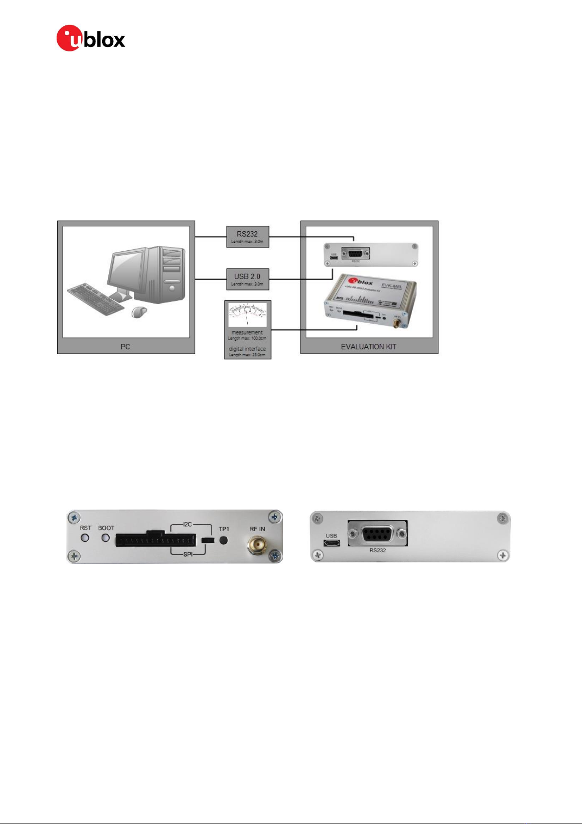
3.1 Interface connection and measurement................................................................................................7
3.2 Active antenna............................................................................................................................................. 7
3.3 Evaluation unit.............................................................................................................................................7
3.3.1 Antenna connector............................................................................................................................. 7
3.3.2 USB ........................................................................................................................................................8
3.3.3 UART .....................................................................................................................................................8
3.3.4 RST button........................................................................................................................................... 8
3.3.5 Safe boot button................................................................................................................................. 8
3.3.6 Slide switch .......................................................................................................................................... 9
3.3.7 Front connector .................................................................................................................................. 9
3.3.8 LED.......................................................................................................................................................10
3.3.9 Backup battery ..................................................................................................................................10
3.3.10 GNSS configuration .........................................................................................................................11
4Setting up.............................................................................................................................................. 12
4.1 Test vehicle preparation..........................................................................................................................12
4.1.1 Wiring harness of the Head Unit ...................................................................................................12
4.1.2 OBD-II to VSS converter ..................................................................................................................13
4.1.3 Wheel speed sensor .........................................................................................................................13
4.2 EVK-M8L installation ...............................................................................................................................13
4.2.1 Mounting the GNSS antenna .........................................................................................................13
4.2.2 Mounting the EVK-M8L ..................................................................................................................13
4.2.3 Connecting the cables .....................................................................................................................14
4.3 Recommended configuration .................................................................................................................15
4.3.1 Serial port default configuration ...................................................................................................15
4.3.2 ADR configuration ............................................................................................................................15
4.4 Configuration and calibration drive.......................................................................................................18
5Test drives ............................................................................................................................................ 21
6Measuring tracking current ............................................................................................................ 22
7Block diagram ..................................................................................................................................... 23
8Board layout.......................................................................................................................................... 24

EVK-M8L - User guide
UBX-20028627 - R01 Page 4 of 33
C1-Public Contents
9Schematic ............................................................................................................................................. 27
10 Battery replacement ......................................................................................................................... 28
11 Troubleshooting.................................................................................................................................. 29
12 Common evaluation pitfalls ............................................................................................................ 31
Related documents ................................................................................................................................... 32
Revision history.......................................................................................................................................... 32
Contact.......................................................................................................................................................... 33

EVK-M8L User Guide
UBX-20028627 - R01 Product description Page 5 of 33
C1-Public
1Product description
1.1 Overview
The EVK-M8L evaluation kit simplifies the evaluation of the high performance u-blox M8 ADR
positioning products. The built-in USB interface provides both power supply and high-speed data
transfer, and eliminates the need for an external power supply. The u-blox evaluation kits are
compact, and their user-friendly interface and power supply make them ideally suited for use in
laboratories, vehicles and outdoor locations. Furthermore, they can be used with a PDA or a notebook
PC, making them the perfect companion through all stages of design-in projects.
Evaluation kit
Description
Suitable for
EVK-M8L
u-blox M8 Evaluation Kit 3D ADR with on-board sensors
NEO-M8L
Table 1: List of products supported by the EVK-M8L evaluation kit
1.2 Kit includes
Evaluation unit
USB cable
Active GPS / Galileo / GLONASS / BeiDou antenna with 3 m cable
Quick Start card
1.3 Evaluation software
The u-center software installation package for the EVK can be downloaded from www.u-
blox.com/en/evaluation-software-and-tools.
Once the .zip file is downloaded, extract the file contents in the Tools folder and double-click the
extracted .exe file. The software components will be installed in your system and placed under the
“u-blox” folder in the “Start > Programs” menu.
The u-center application is an interactive tool for configuration, testing, visualization and data
analysis of GNSS receivers. It provides useful assistance during all phases of a system integration
project. The latest version of the u-center should be used.
1.4 System requirements
PC with USB interface
Operating system: Windows Vista onwards (x86 and x64 versions)
USB drivers are provided in the evaluation kit installation software

EVK-M8L User Guide
UBX-20028627 - R01 Specifications Page 6 of 33
C1-Public
2Specifications
Parameter
Specification
Serial interfaces
1 USB V2.0
1 RS232, max. baud rate 921.6 kBd
DB9 +/- 12 V level
14 pin –3.3 V logic
1 DDC (I2C compatible) max. 400 kHz
1 SPI –clock signal max 5.5 MHz –SPI DATA max. 1 Mbit/s
Speed Pulse interface
Wheel tick: 3.3 V –24 V logic
Forward / Reverse: 3.3 V –24 V logic
Separate isolated vehicle GND connection for wheel tick and Forward/Reverse
signals.
Timing interface
Time-pulse output
Dimensions
105 x 64 x 26 mm
Power supply
5 V via USB or external powered via extra power supply pin 14 (V5_IN) and common
supply/interface ground pin 13 (GND)
Normal Operating temperature
-40 °C to +65 °C
Table 2: EVK-M8L specifications
⚠THE EVK CASE-WORK IS CONNECTED TO THE COMMON SUPPLY/INTERFACE GROUND PIN.
Contact u-blox technical support for assistance if required.
2.1 Safety precautions
EVK-M8L must be supplied by an external limited power source in compliance with clause 2.5 of the
standard IEC 60950-1. In addition to an external limited power source, only separated or Safety
Extra-Low Voltage (SELV) circuits are to be connected to the evaluation kit, including interfaces and
antennas.
☞For more information about SELV circuits see section 2.2 in Safety standard IEC 60950-1 [7].
⚠CAUTION! IN THE UNLIKELY EVENT OF A FAILURE IN THE INTERNAL PROTECTION CIRCUITRY
THERE IS A RISK OF EXPLOSION WHEN CHARGING FULLY OR PARTIALLY DISCHARGED
BATTERIES. REPLACE THE BATTERY IF IT NO LONGER HAS SUFFICIENT CHARGE FOR UNIT
OPERATION. CHECK THE BATTERY BEFORE USING IF THE DEVICE HAS NOT BEEN OPERATED
FOR AN EXTENDED PERIOD OF TIME.

EVK-M8L User Guide
UBX-20028627 - R01 Device description Page 7 of 33
C1-Public
3Device description
3.1 Interface connection and measurement
To connect the EVK to a PC, use a standard SUBD-9 cable and the included USB cable. The use of
RS232 and external power supply is optional. USB provides both power and a communication
channel.
Connect the wheel tick and forward/reverse signals as well as vehicle ground (GNDA) to the front
connector.
Figure 1: Connecting the unit for power supply and communication
3.2 Active antenna
The EVK-M8L evaluation kit includes a GPS / Galileo / GLONASS / BeiDou antenna with a 3-meter
cable. It is possible to connect various active and passive GNSS antennas with SMA connectors to
the evaluation unit.
The recommended maximum antenna supply current for active antennas is 30 mA.
3.3 Evaluation unit
Figure 2 shows the front and the rear panel of the EVK-M8L evaluation unit.
Front panel
Rear panel
Figure 2: EVK-M8L evaluation unit –front and rear panels
3.3.1 Antenna connector
An SMA female jack is available on the front side (see Figure 2) of the evaluation unit for connecting
an active or passive antenna. The EVK provides a DC supply at the RF input of 3.3 V for active
antennas. The maximum supported antenna current is 30 mA; internal protection limits the
maximum short circuit current to 60 mA.
To avoid the damage of RF input caused by ESD or Electrical Overstress, and to seek maximum
consistency and repeatability of performance independently of the RF component used, the EVK-
M8L has an onboard LNA.

EVK-M8L User Guide
UBX-20028627 - R01 Device description Page 8 of 33
C1-Public
⚠The connector is only to be used with a GNSS antenna or simulator. Do not connect this
equipment to cable distribution systems.
3.3.2 USB
A USB V2.0 compatible serial port is featured for data communication and power supply.
3.3.3 UART
The evaluation unit includes an RS232 DCE port for serial communication that is compatible with PC
serial ports.
Connect using a straight RS232 serial cable with male and female connectors to the DTE port on
your PC. The maximum cable length is 3.0 meters. To configure the RS232 port, use the UBX-CFG-
PRT command in the u-center application. The maximum operating baud rate is 921.6 kBd.
If you are using a USB to RS232 adaptor cable, you can connect it directly to the evaluation kit RS232
port.
The 9-pin D-SUB female connector is assigned as listed in Table 3:
Pin no.
Assignment
1
not connected
2
TXD, GNSS Transmit Data, serial data to DTE
3
RXD, GNSS Receive Data, serial data from DTE
4
not connected
5
GND
6
not connected
7-9
not connected
Table 3: SUB-D9 connector pin description for EVK-M8L
3.3.4 RST button
The RST button on the front panel resets the unit. To avoid an inadvertent reset, the button is
recessed.
3.3.5 Safe boot button
This is used to set the unit in safe boot mode. In this mode the receiver executes only the minimal
functionality, such as updating new firmware into the SQI flash. In order to set the receiver in
safeboot mode follow these steps.
Press the BOOT button and keep holding it down
Press the RST button
Release the RST button
Release the BOOT button
If the UART interface has to be used, a training sequence has to be sent to the receiver.
The training sequence is a transmission of two bytes 0x55 55 at the baud rate of 9600 Bd. Wait
for at least 100 milliseconds before the interface is ready to accept commands.

EVK-M8L User Guide
UBX-20028627 - R01 Device description Page 9 of 33
C1-Public
3.3.6 Slide switch
Use the slide switch on the front panel to choose between I2C (and UART) and SPI communication
ports. You must reset the unit by pressing the RST button when the slide switch has been changed.
1. I2C: With this selection, the EVK operates with the UART (RS232 DB9 –rear panel or the 3.3 V
level TXD (MISO), RXD (MOSI) at the front panel). Also the communication via 3.3 V DDC interface
(I2C) is selected.
2. SPI: With this selection, the EVK operates only with the SPI interface. RS232 (DB9) is switched
off.
3.3.7 Front connector
This 14-pin connector provides access to additional functionality to the EVK using various interface
pins. Most importantly, it provides the interface to the vehicle speed pulse (WHEELTICK) input. The
WHEELTICK signal should be adequately de-bounced before application to the EVK input.
The connector also enables measurement of the current used by the EVK. For accurate
measurements, it is recommended to use a cable of at most 1 meter in length.
We recommend using the ACE-AM-0 mating connector or equivalent available from our online shop.
All pins are ESD-protected.

EVK-M8L User Guide
UBX-20028627 - R01 Device description Page 10 of 33
C1-Public
Pin no.
Pin name
I/O
LEVEL
Description
14
V5_IN
I
4.75 V - 5.25 V
Power input –can be used instead of USB
13
GND
I
-
Common ground pin for case-work, power and serial interface
connections
12
P1A (VCC)
O
3.3 V
Power output –max. current supply 100 mA
1Ω 1% resistor for over-all current measurement to pin 11 (P1B)
NOTE: the current also includes LNA
11
P1B
O
Second connection for overall current measurement
10
P2A
O
3.0 V
Battery output (unloaded)
100 Ω 1% resistor for battery backup current measurement to pin 9
(P2B)
NOTE: There is a current protection to 3 mA. See the circuit in Figure
16 (D2, D4, R29).
9
P2B
O
Second junction for battery backup current measurement
8
TIMEPULSE
O
3.3 V
Time pulse (internally buffered output)
7
WHEELTICK
I
3.3 V - 24 V
Wheel tick input
6
FWD
I
3.3 V - 24 V
Forward/reverse input for speed pulse
5
SDA / CS
I/O
3.3 V
If the slide switch is on I2C, the DDC interface is selected; Function:
data input / output
If the slide switch is on SPI, the SPI interface is selected; chip select
input –LOW ACTIVE
4
SCL / SCK
I/O
3.3 V
Clock input / output
3
TxD / MISO
I/O
3.3 V
If the slide switch is on I2C, the DDC interface is selected / UART TxD
(3.3 V level)
If the slide switch is on SPI, the SPI interface is selected; Master in,
Slave out (MISO)
2
RxD / MOSI
I/O
3.3 V
If the slide switch is on I2C, the DDC interface is selected / UART RxD
(3.3 V level)
If the slide switch is on SPI, the SPI interface is selected; Master out,
Slave in (MOSI)
1
GNDA
I
-
Isolated ground pin to be connected with wheel tick and
Forward/Reverse signals
Table 4: Connector pin descriptions for EVK-M8L (pins numbered from right to left on the front panel)
⚠THE EVK CASE-WORK IS CONNECTED TO THE COMMON SUPPLY/INTERFACE GROUND PIN.
Contact u-blox technical support for assistance if required.
3.3.8 LED
On the front panel of the unit, a single blue LED may be configured to follow the receiver time pulse
signal using the UBX-CFG-TP5 message. The time pulse may be configured so that the LED starts
flashing at one pulse per second during a valid GNSS fix. If there is no GNSS fix, the LED will only light
up, without flashing. The time pulse is enabled by default in the EVK-M8L.
3.3.9 Backup battery
The evaluation unit includes a backup battery. This is necessary to store calibration and navigation
information between operations and to enable immediate startup in DR mode, and fast acquisition
of GNSS signals.

EVK-M8L User Guide
UBX-20028627 - R01 Device description Page 11 of 33
C1-Public
Battery
Type
Capacity
Operating temperature range
RENATA 3.0 V Li / MnO²
CR2450
540 mA
-40 °C to +85 °C
Table 5: Backup battery for EVK-M8L
If the built-in backup battery runs low or is empty after a long storage period, purchase the battery
described above for replacement (refer to section 10 for battery replacements guidelines)
⚠CAUTION! RISK OF EXPLOSION IF BATTERY IS REPLACED BY AN INCORRECT TYPE. DISPOSE
OF USED BATTERIES ACCORDING TO THE INSTRUCTIONS!
3.3.10 GNSS configuration
The EVK-M8L supports GPS, QZSS, GLONASS, Galileo and BeiDou.
The GNSS to be used can be configured in u-center (View > Messages View > UBX-CFG-GNSS). For
more information, refer to the u-center User guide [6], and the u-blox 8 / u-blox M8 Receiver
Description including Protocol Specification [5]

EVK-M8L User Guide
UBX-20028627 - R01 Setting up Page 12 of 33
C1-Public
4Setting up
4.1 Test vehicle preparation
The test vehicle should allow easy installation. A practical vehicle for testing purposes is a hatchback
passenger car. The EVK relies on WHEELTICK and FWD signals from the vehicle as an essential
major part of its dead reckoning functionality. The characteristics of the signal inputs are specified
in Table 4 (HW interface).
Alternatively, if you have access to the proprietary CAN messages of the vehicle, the same
information may be delivered as UBX-ESF-MEAS messages on a communication port (SW interface).
Note that EVK-M8L default configuration is set to HW input signals. Should UBX-ESF-MEAS
messages be used to input WHEELTICK and FWD information instead of HW signals, a change in
the configuration is required using UBX-CFG-ESFWT.
☞More information on the SW interface can be found in the u-blox 8 / u-blox M8 Receiver
Description including Protocol Specification [5], or contact u-blox technical support for further
SW interfacing solutions.
The next sections focus on use of the HW interface.
The WHEELTICK signal:
Shall be representative of the distance traveled by the vehicle’s reference point. The reference
point is the mid-rear axle of the vehicle. Wheel ticks from the front wheels may be used as an
alternative with some compromise in performance.
Shall be a series of (absolute wheel tick) pulses with one pulse corresponding to less than 0.4
meters of distance traveled. For best results one pulse should correspond to about one
centimeter of distance traveled.
Shall be available regardless of the direction of driving.
Shall be adequately de-bounced before application to the EVK input.
The FWD signal:
Shall indicate the direction of driving, i.e. forward or reverse.
May have either polarity. By default the polarity will be detected automatically in normal use, but
can also be configured explicitly with UBX-CFG-ESFWT command (see Figure 5).
May indicate either forward or reverse when the vehicle is stationary.
Most cars since 1980 provide a vehicle speed sensor (VSS) signal, which, for example, may be
available on the OBD/OBD-II connector as a signal or CAN message. For evaluation purposes, you can
use a device which converts the CAN messages to hardware WHEELTICK signals (see section 4.1).
The VSS and forward/reverse signals are also often available directly on standard Head Unit
connectors. If necessary, consult the vehicle service manuals, head unit installation manuals for the
vehicle, or a certified automotive electrician.
If the vehicle does not provide the signals readily, you can use external sensors as described in
section 4.1.3 below.
4.1.1 Wiring harness of the Head Unit
Remove the Head Unit (make sure you know the possible re-activation pass code). Locate the wheel-
tick and forward/reverse signals (check voltage and polarity).

EVK-M8L User Guide
UBX-20028627 - R01 Setting up Page 13 of 33
C1-Public
4.1.2 OBD-II to VSS converter
Connect a device, such as the BCI-6 from Beijer Automotive BV, to the CAN bus of your vehicle. The
location of the CAN interface can be found, for example, from the database maintained by Beijer
Automotive BV. Often the CAN bus is available on the OBD-II diagnostics connector. The BCI-6 will
read the speed and direction information from the CAN bus, and convert these to wheel tick pulses
and direction signals. The wheel tick pulse is available on the SPEED output connector of the BCI-6
and the direction signal is available on the REVERSE connector.
The BCI-6 unit is compatible with a wide range of vehicles using high-speed CAN and low-speed CAN.
A full list of supported vehicles can be found from the Beijer Automotive BV website.
4.1.3 Wheel speed sensor
Alternatively you can use a wheel speed sensor connected to the hub of a wheel. We recommend
connecting to a rear wheel. Note that the wheel tick from one wheel does not exactly describe the
speed of the reference point (mid-read axle) in turns. However, even one wheel provides sufficiently
good measurement for most evaluation purposes. Several manufacturers offer these sensors, for
example, Peiseler GmbH and PEGASEM Messtechnik GmbH.
Figure 3: WSS2 wheel speed sensor from PEGASEM Messtechnik GmbH. WSS2 provides wheel tick and direction signals.
4.2 EVK-M8L installation
The EVK-M8L ships with an active GPS / GLONASS / BeiDou magnetic mount antenna with a 3-meter
cable.
The following sections describe the steps required to complete the EVK-M8L hardware installation.
4.2.1 Mounting the GNSS antenna
Attach the antenna to the car; for the best performance, attach it on the roof as shown in Figure 4.
Bring the antenna cable in through the window or door. Be careful not to damage the antenna cable.
4.2.2 Mounting the EVK-M8L
The EVK-M8L should be firmly attached to the car body so as to avoid any movement or vibration
with respect to the car body. The EVK should not be attached to any ‘live’ (unsprung) part of the
vehicle’s suspension. Often it is enough to use strong double-sided tape or Velcro tape glued to the
bottom of the EVK-M8L casing. If necessary, mounting brackets may be attached using the end-
plate retaining bolts (M3). The EVK must be secured against any change in position and particularly
its orientation with respect to the vehicle frame.

EVK-M8L User Guide
UBX-20028627 - R01 Setting up Page 14 of 33
C1-Public
The orientation of the EVK in all three planes must be established accurately either by measurement
or by using the automatic calibration process described in section 4.3.2.2. Dead reckoning
performance will be seriously impaired by errors or changes in the orientation of the EVK.
⚠The EVK case-work, antenna and USB connectors are linked internally to the common
supply/interface ground (pin 13).
☞In order to achieve the best possible performance, the GNSS antenna should be positioned on the
vehicle roof over the EVK. If GNSS antenna is placed at a significant distance from the EVK,
position offsets can be introduced which might affect the accuracy of the navigation solution. In
order to compensate for the position offset advanced configurations can be applied. Contact u-
blox support for more information on advanced configurations.
Figure 4: Example installation of the GNSS antenna and the EVK-M8L
4.2.3 Connecting the cables
We recommend using the ACE-AM-0 mating connector (available from the u-blox web shop) because
it locks securely to the front connector. You will need to solder the necessary I/O cables to signal
sources (e.g. WHEELTICK, FWD and GNDA) and outputs as specified in Table 6.
☞The WHEELTICK and FWD inputs must be presented to the EVK at 3.3 V - 24 V logic levels.
Connect GNDA from your input signals as well.
1. Connect the finalized cable to the front connector of EVK-M8L.
2. Connect the unit to a PC running Microsoft Windows by
2.1. USB: Connect via USB port or
2.2. UART: Connect via RS232. Set slide switch to I2C or
2.3. SPI / I2C compliant DDC: Connect corresponding pins (see Table 4 for pin description). Set
slide switch accordingly to SPI or I2C.
3. Press the RST button after changing the switch.
4. The device may be powered either via USB or from a 5 V supply via the V5_IN input on the front.
5. Connect the RF cable of the GNSS antenna to the RF IN connector.
6. Start the u-center GNSS Evaluation Software and select the corresponding COM port and baud
rate.
7. Refer to the u-center User guide [6] for more information.

EVK-M8L User Guide
UBX-20028627 - R01 Setting up Page 15 of 33
C1-Public
4.3 Recommended configuration
Only NMEA messages have been activated by default. During calibration and test drives we
recommend enabling certain UBX messages (see section 4.4 and section 5).
For optimum navigation performance, the recommended navigation rate configuration is as follows:
The default DR/GNSS-fused navigation solution update rate is 1 Hz. You can set the navigation
update rate with the message UBX-CFG-RATE. (In this mode, navigation rates up to 30 Hz are also
available from the UBX-HNR-PVT message.)
Also, you need to configure the installation-specific ADR configuration parameters discussed in
section 4.3.2.
4.3.1 Serial port default configuration
Parameter
Description
Remark
UART port 1, input
UBX and NMEA protocol at 9600 Bd
UART port 1, output
UBX and NMEA protocol at 9600 Bd
Only NMEA messages are activated
USB, input
UBX and NMEA protocol
USB, output
UBX and NMEA protocol
Only NMEA messages are activated
Table 6: Default configuration
4.3.2 ADR configuration
The following sections describe how to configure the parameters specific to the installation.
4.3.2.1 WHEELTICK and FWD configuration
By default, the wheel-tick count is based on the rising edge of the wheel-tick pulse signal. To improve
performance with lower rate, mechanically derived wheel tick signals, the receiver may be configured
to use both the rising and falling edges of the wheel tick signal on the condition that the wheel-tick
pulses have approximately 1:1 mark:space ratio regardless of speed.
The wheel tick direction pin polarity is now automatically initialized. The car needs to drive with a
minimum speed of 30 km/h for proper initialization.
You can also manually establish the polarity of your FWD signal (e.g. with a multimeter when the gear
is set forward). Depending on the setup you may have to drive slowly as well. Set the Direction Pin
Polarity (FWD) correctly using message UBX-CFG-ESFWT or in u-center (see Figure 5 below). Usually
there is no need to change other parameter values. For more information, refer to the u-blox 8 / u-
blox M8 Receiver Description including Protocol Specification [5]. Click the Send button in u-center
if you changed the default values.
WHEELTICK maximum frequency is 20 kHz. Minimum recommended pulse width is 10 us. The wheel
tick pulse must have a clean slope transition, the input is Schmidt-triggered.This signal input is
single edge triggered. Pulse interval (WT resolution) must be less than 40 cm per tick over distance
traveled. The wheel tick pulse output shall change linearly with the change in speed (navigation filter
estimates only the linear scale factor).
If the vehicle is standing still, there should be no wheel tick pulses. This is particularly important at
system shut down and power up. If there is a dead-band (wheel tick pulse does not change or is not
output below a certain speed) performance will be affected.

EVK-M8L User Guide
UBX-20028627 - R01 Setting up Page 16 of 33
C1-Public
Figure 5: u-center showing the default values of UBX-CFG-ESFWT
☞By default, it is assumed that the EVK-M8L receives WHEELTICK and FWD signals on its
dedicated HW pins. If this is not the case and UBX-ESF-MEAS messages are used, EVK-M8L
configuration must be modified using UBX-CFG-ESFWT: set “Use WT Pin for Speed Meas. (L-
Modules)” bit to 0 and set all other parameters according to your setup. See the u-blox 8 / u-blox
M8 Receiver Description including Protocol Specification [5] for details. In such a case, use UBX-
CFG-CFG command (see Figure 7) to save the configuration permanently and make sure the EVK
will always stay in this particular configuration.
4.3.2.2 Sensor/IMU mount angles configuration
Dead reckoning performance relies on accurate configuration of the sensor mount configuration
angles. The angles may be measured and configured manually or established using the Automatic
IMU-mount Alignment feature described below. In either case the configuration is made using
message UBX-CFG-ESFALG.
If you do not know or are not completely certain how to measure the Sensor-mount Misalignment
Angles correctly, enable the Automatic IMU-mount Alignment (see Figure 6 below). Click the Send
button after selelcting the “Automatic IMU-mount Alignment” box. The correct angles will then be
determined automatically in Phase II of the calibration drive (see section 4.4).

EVK-M8L User Guide
UBX-20028627 - R01 Setting up Page 17 of 33
C1-Public
Figure 6: u-center showing how to enable Automatic IMU-mount Alignment with UBX-CFG-ESFALG
If you know the IMU-mount Misalignment Angles, enter those values into the UBX-CFG-ESFALG
dialog shown in Figure 6. Make sure the “Automatic IMU-mount Alignment” is unselected. Click the
Send button. For more information, refer to the u-blox 8 / u-blox M8 Receiver Description including
Protocol Specification [5].
☞Automatically determined IMU-mount Alignment angles do not survive a cold start (either by
command or loss of the battery backup supply). If it is important that automatically determined
angles continue to be used after the next cold start, follow the procedure in section 4.3.2.3.
☞If the user reverts to factory defaults with UBX-CFG-CFG command, the UBX-CFG-ESFALG with
correct configuration values (yaw, pitch, roll) shall be issued again. For example, in the basic use
case when the EVK-M8L is mounted flat (label side up) and X-axis on the label is pointing forward,
the user should configure it in UBX-CFG-ESFALG as (yaw, pitch, roll) = (0,0,0).
4.3.2.3 Saving the configuration permanently
If, for example, automatically determined IMU mount angles should be used after the next cold start,
they can be saved in the receiver’s non-volatile memory and will be re-used until the automatic
alignment feature is next enabled. Proceed as follows:
When configuration is indicated as completed in the UBX-ESF-STATUS and UBX-ESF-ALG
windows, copy the angles from UBX-ESF-ALG display to the UBX-CFG-ESFALG dialog. Unselect
the “Automatic IMU-mount Alignment” in UBX-CFG-ESFALG dialog and click the Send button.
Save the configuration as described below.
The entire current configuration of the receiver (including configuration data and all ADR
parameters) can be saved to BBR and non-volatile memory (flash) by sending UBX-CFG-CFG
command (see Figure 7 below).

EVK-M8L User Guide
UBX-20028627 - R01 Setting up Page 18 of 33
C1-Public
Figure 7: u-center showing how to save current configuration with UBX-CFG-CFG
4.4 Configuration and calibration drive
Before the EVK-M8L can use the vehicle’s speed and forward information as well as data from the
integrated sensors (gyroscopes and accelerometers), the receiver must gather calibration
information from a sufficient number of left and right turns. This information needs to be gathered
only once for a particular installation if the ADR configuration parameters are then permanently
stored to flash (see section 4.3.2.3). We recommend that a dedicated co-driver observes the
progress of the calibration drive using u-center.
☞Although the initialization and calibration process will complete eventually, the sequence below
(illustrated in Figure 8) can be used to achieve more rapid calibration for the purposes of
evaluation.
☞To ensure quick calibration the driving location needs to have very good GNSS visibility. The
terrain needs to be flat and speed must be high enough.
The calibration time can be improved if the following procedure is carried out:
Drive the car to an open area. An example of a suitable place is a very large, empty parking area. Use
u-center to monitor the process, enable the UBX-ESF-STATUS message.
Phase I. Stop the car, but keep the engine running. Power on the EVK-M8L, for example via USB
to PC. The co-driver should open u-center and enable the messages and views shown in Figure 9.
Wait for a good GNSS position fix. Stand still for another 3 minutes.
Phase II. Start driving a figure-8 pattern (see Figure 8).
Phase III. Drive straight for 500 meters at least 40 km/h.
Phase IV. Drive curves and straight segments for 5 minutes with good satellite visibility. The
segments should include a section where the speed exceeds 60 km/h for at least 10 seconds.
Phase V. This is a continuous fine calibration process running in the background. During this
phase, e.g., the gyroscope temperature compensation table gradually fills in.

EVK-M8L User Guide
UBX-20028627 - R01 Setting up Page 20 of 33
C1-Public
Figure 10: All sensors have reached Calibrated status. The setup is ready for test drives.
Table of contents
Other Ublox Motherboard manuals

Ublox
Ublox EVK-NINA-B1 User manual

Ublox
Ublox EVK-ANNA-B112 User manual

Ublox
Ublox EVK-M91-00-01 User manual

Ublox
Ublox EVK-M8 User manual

Ublox
Ublox EVK-NINA-B3 Series User manual

Ublox
Ublox EVK-M8F-0-01 User manual

Ublox
Ublox EVK-M8QSAM User manual

Ublox
Ublox EVK-ANNA-B4 User manual

Ublox
Ublox C099-F9P User manual

Ublox
Ublox XPLR-HPG-1 User manual

Ublox
Ublox EVK-M101 User manual

Ublox
Ublox EVK-M8QSAM User manual

Ublox
Ublox EVK-R6 User manual

Ublox
Ublox IRIS-W10 Series User manual

Ublox
Ublox EVK-M9DR User manual

Ublox
Ublox TOBY-R2 Series User manual

Ublox
Ublox C030-R412M User manual

Ublox
Ublox EVK-R41Z User manual

Ublox
Ublox C099-F9P User manual

Ublox
Ublox EVK-M8xZOE Series User manual