UES perfectMelt User manual

Operating Instructions
perfectMelt
Hot glue system

UES AG · Breuerhofstr. 48 · 4 80 Krefeld
ag.net
2
Contents
ContentsContents
Contents
Introduction ............................................................................................................................................. 3
Safety Instructions ................................................................................................................................... 4
Example of a hot glue system .................................................................................................................. 6
Installation ............................................................................................................................................... 8
Checking the components ................................................................................................................... 8
Assembly and mounting of the tank system ....................................................................................... 8
Connection of the tank system ............................................................................................................... 9
Electrical connection ........................................................................................................................... 9
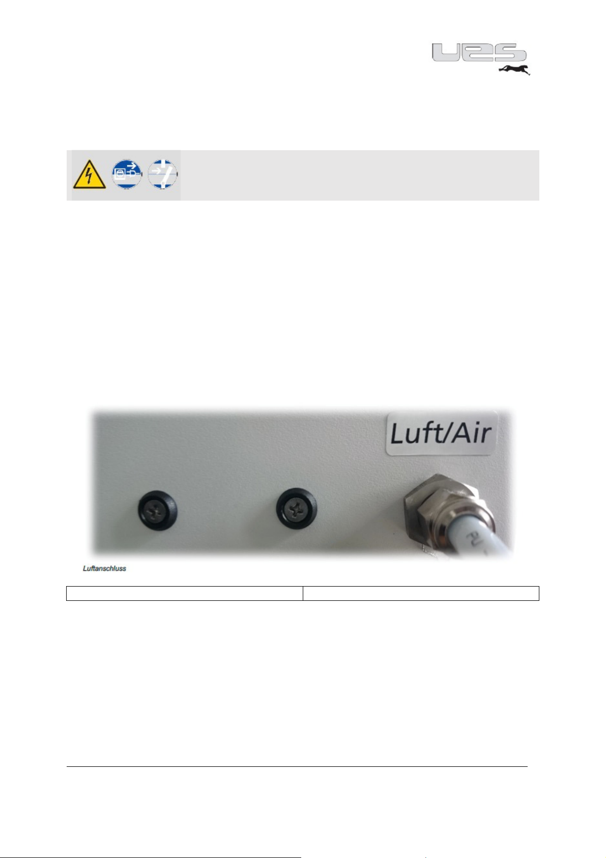
Air connection ..................................................................................................................................... 9
Hose connection .................................................................................................................................. 9
Application head connection............................................................................................................. 10
Add glue ............................................................................................................................................. 10
Service ................................................................................................................................................... 11
Commissioning .................................................................................................................................. 13
Setting the pump pressure ................................................................................................................ 14
Automatic pressure release .............................................................................................................. 14
Individual settings ............................................................................................................................. 15
Menu overview .................................................................................................................................. 16
Pump: ................................................................................................................................................ 16
Options: ............................................................................................................................................. 1
Service: .............................................................................................................................................. 18
Format: .............................................................................................................................................. 19
Standby (temperature reduction) ..................................................................................................... 20
Maintenance ......................................................................................................................................... 21
Bleeding the system .............................................................................................................................. 22
Changing the filter ................................................................................................................................. 23
Basic cleaning ........................................................................................................................................ 24
Mechanical malfunctions ...................................................................................................................... 25
Problems with the glue application....................................................................................................... 25
Socket assignment on UES systems, depending on the model ............................................................. 26
perfectMelt Replacement parts ............................................................................................................ 2
Recycling ................................................................................................................................................ 28
Electrical connections ............................................................................................................................ 29
Fuses ...................................................................................................................................................... 31
Technical data ....................................................................................................................................... 32
Electrical data ........................................................................................................................................ 34
Connection scheme ............................................................................................................................... 46

UES AG · Breuerhofstr. 48 · 4 80 Krefeld
ag.net
3
Introduction
IntroductionIntroduction
Introduction
UES hot glue systems meet your highest expectations in terms of quality, labour and production
reliability as well as maintenance and user friendliness.
By combining cutting-edge control technology with comfortable and complete features, you have the
greatest possible benefit. An extremely compact design and the modular extension option assure
variable use for versatile applications.
The UES tank system "perfectMelt" is equipped with carefully selected components of very high
quality. When adhering to these Operating Instructions, a long-term and unlimited use of the device
is possible.
Along with a full range of standard applications of adhesive technology with tank systems, hose and
gun systems, we also offer individual solutions and system components for special applications in
various industrial sectors.
With the adhesive application systems of the "perfectMelt" series, the process is conducted in the
context of the hotmelt adhesive application. In other words, depending on the application, the
adhesive systems are incorporated into production or packaging machines, and, as such,are part of
the equipment.
In the operation of adhesive application systems for hotmelt, the adhesive is processed at high
temperatures and with high-pressure material. For this reason, safety precautions are to be taken
during installation, operation and maintenance.
In the description of the operation of the system, these safety precautions are marked by safety
symbols and, if applicable, further information.
The safety precautions described here refer exclusively to the handling of the adhesive system.
Before commissioning, the Operating Instructions are to be read in full in order to ensure safety and
proper operation. The device owner or operator is responsible for compliance with the safety
regulations.
All operating instructions and manuals of the company UES are copyrighted. Copying, reproduction
(or part thereof), translation, etc. is not allowed without permission by UES AG. Additional copies of
these Operating Instructions can be acquired directly from the factory. Furthermore, the
manufacturer is not responsible for the accuracy of the contents of this manual.
These Operating Instructions are subject to changes.
UES AG
Krefeld, February 2016

UES AG · Breuerhofstr. 48 · 4 80 Krefeld
ag.net
4
Safety Instructions
Safety InstructionsSafety Instructions
Safety Instructions
The following Safety Instructions must be observed!
Caution:
Before any repair and adjustment work, unplug from the mains
Installation and maintenance work may only be performed by trained personnel.
Only those individuals shall be considered suitable who are qualified by specialised training and
experience in dealing with these or similar devices, who know the relevant safety and accident
prevention regulations, and who therefore can recognise and avoid hazards.
Work on the adhesive application system may generally only be conducted when the voltage has
been turned off and the compressed air has been blocked (depressurise the system).
The system must not be operated without the appropriate covers and safety panels. Be careful of
non-covered moving and rotating parts, such as motor and pump shafts, hub and swivelling
mechanisms!
Caution: Do not use the system for any purpose other than that for which it is intended
On many non-covered parts of the applicator device, the hot glue hoses and application guns consist
of high temperatures during operation. Hot and pressurised adhesive may cause severe skin burns.
Therefore, always wear protective clothing, gloves and safety goggles when working on the system,
such as when filling the melting tank or connecting and installing the hoses and valves. Some
adhesives produce toxic fumes that have to be extracted. The hot melt adhesive application
equipment may not be operated under the following circumstances:
- In the vicinity of volatile substances or explosive materials and gasses
- Without adequate protection
- At temperatures of less than 5 °C or more than 45 °C
Security measures with respect to the adhesive
Security measures with respect to the adhesiveSecurity measures with respect to the adhesive
Security measures with respect to the adhesive
When working with molten hot glue, always be extremely careful! These materials solidify very
quickly, even at high temperatures, so they can still be very hot even in their solid state and can
result in burns when in brought into contact with the skin. The safety precautions of the adhesive
manufacturer are to be observed. These can be found on the data sheet of the adhesive. Comply
with the processing temperatures recommended by the glue manufacturer!
When working with hot melt, wear gloves, safety glasses and long sleeves to prevent burns. In the
case of a burn, do not attempt to remove the glue from a person's skin; instead, hold the wounded
site under cold water until the glue has cooled and then contact a physician.
Safeguards with respect to the production machine
Safeguards with respect to the production machineSafeguards with respect to the production machine
Safeguards with respect to the production machine
For the safety regulations in dealing with the production or packaging machine, please refer to the
documentation supplied with these devices.
For installation and maintenance work, the Safety Instructions for the parent machine in which the
adhesive application system is installed must be observed.

UES AG · Breuerhofstr. 48 · 4 80 Krefeld
ag.net
5
Safety symbols
Safety symbolsSafety symbols
Safety symbols
The safety symbols below highlight activities in this manual where increased caution is necessary.
The proposed safety precautions should be observed in any case.
Attention, general safety information:
Information regarding compliance with the Safety Information for adhesives
and other equipment. Special instructions may follow.
Warning about hot surfaces:
achine parts may have an operating temperature.
Danger – high voltage:
The work may only be performed by qualified personnel.
Warning of hand injury:
Unsafe handling may lead to crushing.
Warning – hot liquids may escape uncontrollably!
Unplug before opening!
Use protective clothing!
Unlock before starting work!
Wear eye protection!
Wear protective gloves!
Wear face protection!

UES AG · Breuerhofstr. 48 · 4 80 Krefeld
ag.net
6
Example of a hot glue system
Example of a hot glue systemExample of a hot glue system
Example of a hot glue system
(Connecting parts are not supplied with the perfectMelt)
Tankdeckel
Tank cap
Pumpe
Pump
Tank
Tank
Heißleim
Hot glue
Inline Filter
In
-
line filter
Tankfilter
Tank filter
Heizschlauch
Heat tube
Versorgungsblock
Supply block
Düse
Valve
Modul
Module
The fuel tank cap closes the tank. After filling, please use the fuel tank cap to close the tank of your
perfectMelt system.
The hot glue is melted in the tank. Your perfectMelt has two adjustable heating zones: the tank "t1"
and the manifold block "t2" (distribution block to connect the hot glue hoses).
The pump places the melted glue under pressure. UES-pumps have a translation ratio of 14:1. In
other words, at a set air pressure of 2 bar, there is a material pressure of 28 bar.
To prevent contamination in the hoses and application guns, the perfectMelt has a (tank) glue filter.
The hot glue hoses are connected to the glue dispenser. They are heated electrically and are
connected with the perfectMelt by a plug.
As an option, an in-line filter can be installed between the hose end and the gun.
The supply block is supplied with hot glue via the tube. It is also heated and is connected to the hose
electrically.

UES AG · Breuerhofstr. 48 · 4 80 Krefeld
ag.net
One or more modules are bolted onto the supply block. The modules open and close by air control
(via a solenoid valve).
For standard modules, screwable vents are necessary. Different nozzles are available for different
applications.

UES AG · Breuerhofstr. 48 · 4 80 Krefeld
ag.net
8
Installation
InstallationInstallation
Installation
Checking the comp
Checking the compChecking the comp
Checking the components
onentsonents
onents
After unpacking, please check all the components of your perfectMelt and (if applicable) the hot glue
hoses and application heads for any damage.
If you notice any damage, please contact UES AG immediately.
perfectMelt parts list
•perfectMelt system
•Manual
•Filter wrench
Assembly and mounting of the tank system
Assembly and mounting of the tank systemAssembly and mounting of the tank system
Assembly and mounting of the tank system
Warning
To prevent injury caused by falling, the tank system has to be firmly screwed
together with the production machine in any case.
The tank system is equipped with two mounting brackets. These angles have 9 mm holes to secure
the tank system with M8 bolts to the production machine. For this purpose, holes that are about 9
mm in diameter have to be drilled in the seat for the tank system of the production machine.
The tank system should be positioned so that an operator is not ergonomically impaired. This
particularly applies to settings on the control panel, filling the tank and maintenance work, such as
filter changes.
Warning
Please make sure that, when drilling holes, no cables, pipes or other equipment installations are
damaged

UES AG · Breuerhofstr. 48 · 4 80 Krefeld
ag.net
9
Connection of the tank system
Connection of the tank systemConnection of the tank system
Connection of the tank system
(necessary connections)
Electrical connection
Electrical connection Electrical connection
Electrical connection
Warning
The work may only be performed by qualified personnel.
The power supply has to be interrupted.
Necessary: 400-V-(3L/N/PE/50 Hz) plug/connection.
The fuse for each phase cannot be more than 16A.
As an option, the tank system can be factory fitted with a connection cable. The power supply is
connected directly in the control box
Please only use the provided and designated terminals.
Only use the lines with the appropriate wire size as a feed.
For the performance data, please refer to the technical data.
Air connection
Air connectionAir connection
Air connection
Compressed air supply 6 bar (oil and anhydrous)
Connection via PK 8* 1.25 pneumatic hose.
Hose connection
Luftanschluss
Air connection
Hose connection
Hose connectionHose connection
Hose connection
Hose connecting nipple (fittings)
The system is equipped with two glue nipples by the factory.
The corresponding electrical connections are labelled 1 & 2 accordingly.
To connect a hose, the end cap has to be placed under resistance with an SW 1 wrench.
The electrical connection is made by inserting the plug located on the hose into the socket located on
the system.

UES AG · Breuerhofstr. 48 · 4 80 Krefeld
ag.net
10
Application head connection
Application head connectionApplication head connection
Application head connection
The glue connection nipple on the application head has to be connected to the hose connection
nipple on the hose. You will also need an SW 19 wrench.
The electrical connection is established by inserting the plug located on the application head into the
socket located on the glue hose.
Warni
ng
Make sure that there is an absolutely tight connection between the system, the hoses and the
guns via the screwed glue nipple. Otherwise, any escaping glue can lead to severe burns.
Pneumatic components are designed and constructed according to the applicable standards and
calculations such that, under the intended conditions of use, rupture or failure due to fatigue or
wear is not expected to occur.
Add glue
Add glue Add glue
Add glue
Caution:
When refilling the glue, any spouting hot glue can cause injuries.
In any case, observe the safety regulations for handling melted adhesives.
•Do not leave the adhesive supply open; only store it in sealed containers.
•The fuel tank lid should be able to be opened without foreign bodies (such as scraps of paper)
being able to fall into it.
•Before filling, check to see whether the tank and the adhesive supply are clean and free of debris.
•Do not overfill your system. Add adhesive carefully to a max. 20 mm below the tank opening.
•Close the tank lid after filling. This prevents unwanted foreign matter from entering the tank or
hot adhesive vapours from escaping.
•The tank lid should be closed without it coming into direct contact with the adhesive.
•Do not run your device when it is completely empty. If there is too little adhesive in the tank,
localised overheating can result in
•glue burns and deposits in your system, leading to a malfunction.
•Refer to the data sheet of your adhesive supplier and set your device appropriately.

UES AG · Breuerhofstr. 48 · 4 80 Krefeld
ag.net
11
Service
ServiceService
Service
(general)
Our perfectMelt is equipped with a touch-sensitive 4.3" colour touch display. You will be guided
through the menu intuitively. If you wish to enter data, touch the screen at the desired location and
enter your values via the input field. Confirm this by pressing ENTER. The display then automatically
jumps back to the so-called Overview after a few seconds. All the important information is displayed
here during operation.
In addition, the perfectMelt has a one-hand safety input wheel. Turn the input wheel until the
desired number is entered. By pressing the wheel, this field is activated. Now activate the input field.
Now set the desired value by turning the wheel again. Confirm this value by pressing the wheel
again. Through these two methods, you can make your entries quickly, easily and intuitively.

UES AG · Breuerhofstr. 48 · 4 80 Krefeld
ag.net
12
Through the menu, you will be informed about the current settings via our traffic light system. In the
heating phase, the corresponding fields are entered in yellow. The percentage of colouring of these
fields provides information on the heating progress. Once all the temperatures have been reached,
these fields are displayed in green. As soon as the ready signal is activated, the entire display
switches to green. You can therefore already see from a distance that your system is ready. If there is
still a problem, the corresponding area is displayed in red. Here, as well, the entire display will
change after a few seconds and turn red. This allows you to see from a distance that something is
wrong.
Warning
Never use sharp objects to adjust the touch panel. This could lead to irreparable damage.
Likewise, the display can be damaged if too much pressure is used when entering data. Always
keep the screen clean so that you can enter data without any problem.

UES AG · Breuerhofstr. 48 · 4 80 Krefeld
ag.net
13
Commissioning
CommissioningCommissioning
Commissioning
Quick start
In order to be able to work with your perfectMelt, you only need a few steps to put it into operation.
All the parameters are pre-set so that you only have to adjust the values to your requirements. You
have made all the electrical and pneumatic connections and connected your peripherals.
Now, turn on the perfectMelt with the main switch. The system is now in the off-line mode. Touch
the screen in the middle of the switch symbol until the system jumps to the on-line mode.
You can also turn the system on via the one-hand safety input wheel. Hold this down until the system
likewise switches to the on-line mode. After a few seconds, the display jumps to the Overview
display. Set the appropriate temperature tank by tapping on the Tank Temperature field.
This opens the input window. Here, enter your value and confirm your entry with Enter. Then, set the
temperatures for each channel that you need. You either enter this area by using the "down arrow
key" or the Overview by touching the Channel temperatures field. Here, activate the hose and the
application head and set the corresponding temperatures. At the end, confirm your entries with
ENTER. The system starts to heat up the individual temperature ranges. Once the temperatures have
been reached, the READY signal will be activated. Now please set the appropriate working pressure
on the pressure regulator.
Your system is ready

UES AG · Breuerhofstr. 48 · 4 80 Krefeld
ag.net
14
Setting the pump pressure
Setting the pump pressureSetting the pump pressure
Setting the pump pressure
The pump working pressure is set at the pressure regulator. The pressure regulator can be secured
against unintended changes by pressing the control knob into a grid position. If you want to adjust
the knob again, first pull it out of the catch position. The set pump pressure can be read on the
pressure gauge. The maximum pump pressure in the perfectMelt is reduced to max. 5.3 bar by the
safety valve. If you need a higher working pressure, please contact our technicians.
Aut
AutAut
Automatic pressure release
omatic pressure releaseomatic pressure release
omatic pressure release
Upon removal of the air supply to the hot glue system, a safety valve opens and pressure in the
hydraulic circuit is released.
When using this function, please note:
•You need an input pressure to the system of at least 4 bar with a quick exhaust function
upon shutdown
•The removal of the input pressure has to be conducted by the customer, such as by opening
a security door and then by switching the main air supply.
•For maintenance tasks in hydraulics, inadvertent switching on of the air after removal of the
input pressure has to be prevented; please follow the instructions in the machine manual for
this purpose. It is also urgently necessary to activate the manual pressure relief devices
(chapter-> Bleeding the system). Of course, the Safety Instructions regarding adhesives are to
be observed (PSA, among others).
The pressure relief function has to be checked regularly, depending on your operating
conditions

UES AG · Breuerhofstr. 48 · 4 80 Krefeld
ag.net
15
Individual settings
Individual settingsIndividual settings
Individual settings
Menu structure = Settings
The settings consist of 4 fields, which are constructed as follows.
In these areas, you can customise your settings and adapt them to your needs.
Caution
!
In the Setting area, you can define your settings simply by using the one-hand safety input wheel.
At the end of the settings, you need to save these settings/changes by clicking on the icon. If
you leave the area without saving, your entries will be lost. The previously pre-set parameters
apply.

UES AG · Breuerhofstr. 48 · 4 80 Krefeld
Tel.: +49 (0) 2151-
2950 · Fax: +49 (0) 2151
Menu overview
Menu overviewMenu overview
Menu overview
Pump
PumpPump
Pump
Menu item
Menu itemMenu item
Menu item
Piston pump
Piston pumpPiston pump
Piston pump
Delay [min.
Delay [min.Delay [min.
Delay [min.
Turn on manually
Turn on manuallyTurn on manually
Turn on manually
Gear pump 1
Gear pump 1Gear pump 1
Gear pump 1
Delay [min.
Delay [min.Delay [min.
Delay [min.
max. speed [U/min
max. speed [U/minmax. speed [U/min
max. speed [U/min
max. pressure [bar
max. pressure [barmax. pressure [bar
max. pressure [bar
Turn on manually
Turn on manuallyTurn on manually
Turn on manually
Gear pump 1
Gear pump 1Gear pump 1
Gear pump 1
Delay [min.
Delay [min.Delay [min.
Delay [min.
max. speed [U/min
max. speed [U/minmax. speed [U/min
max. speed [U/min
max.
max. max.
max. pressure [bar
pressure [barpressure [bar
pressure [bar
Turn on manually
Turn on manuallyTurn on manually
Turn on manually
In this menu section, you can change all settings relative to the pump. From the pump selection
through delays up to turning
on manually for maintenance purposes.
Warning
When the pump is activated and the housing flap is open, there is a danger of getting caught on
the movable piston rod. Therefore, when the housing flap is open, always turn off the air pressure.
UES AG · Breuerhofstr. 48 · 4 80 Krefeld
2950 · Fax: +49 (0) 2151
- 295 8 · info@ues-
ag.net · www.ues
ag.net
Setting
SettingSetting
Setting
Description
DescriptionDescription
Description
Dea / Man / Auto
Deactivate / Manual / Automatic
0-120 min
Pump released only after the delay time
Off / On
Activating the pump only possible in
manual mode
Dea / Man / Auto
Deactivate / Manual / Automatic
0-120
Pump released only after the delay time
0-90 Maximum speed
greatest permissible
Off / On
Activating the pump only possible in
manual mode
Dea / Man / Auto
Deactivate / Manual / Automatic
0-120
Pump released only after the delay time
0-90 Maximum speed
greatest permissible pressure
Off / On
Activating the pump only possible in
manual mode
In this menu section, you can change all settings relative to the pump. From the pump selection
on manually for maintenance purposes.
When the pump is activated and the housing flap is open, there is a danger of getting caught on
the movable piston rod. Therefore, when the housing flap is open, always turn off the air pressure.
ag.net · www.ues
-
16
Deactivate / Manual / Automatic
Pump released only after the delay time
Activating the pump only possible in
Deactivate / Manual / Automatic
Pump released only after the delay time
pressure
Activating the pump only possible in
Deactivate / Manual / Automatic
Pump released only after the delay time
greatest permissible pressure
Activating the pump only possible in
In this menu section, you can change all settings relative to the pump. From the pump selection
When the pump is activated and the housing flap is open, there is a danger of getting caught on
the movable piston rod. Therefore, when the housing flap is open, always turn off the air pressure.

UES AG · Breuerhofstr. 48 · 4 80 Krefeld
Tel.: +49 (0) 2151-
2950 · Fax: +49 (0) 2151
Options
OptionsOptions
Options
Menu item
Menu itemMenu item
Menu item
Setting time / date
Setting time / dateSetting time / date
Setting time / date
Timer
TimerTimer
Timer
Timer On / Off
Timer On / OffTimer On / Off
Timer On / Off
Standby
StandbyStandby
Standby
Reduced temperature [°C
Reduced temperature [°CReduced temperature [°C
Reduced temperature [°C
Standby time [min.
Standby time [min.Standby time [min.
Standby time [min.
Language
LanguageLanguage
Language
PowerFill
PowerFillPowerFill
PowerFill
PowerFill min. [sec.
PowerFill min. [sec.PowerFill min. [sec.
PowerFill min. [sec.
PowerFill max. [sec.
PowerFill max. [sec.PowerFill max. [sec.
PowerFill max. [sec.
FU 1
FU 1FU 1
FU 1
FU 2
FU 2FU 2
FU 2
In this menu section, you can adjust
current time to the weekly program, incl. the standby times and temperatures.
UES AG · Breuerhofstr. 48 · 4 80 Krefeld
2950 · Fax: +49 (0) 2151
- 295 8 · info@ues-
ag.net · www.ues
ag.net
Setting
SettingSetting
Setting
Description
DescriptionDescription
Description
xx:xx xx:xx:xxxx
current time current date
Mon.-Sun. On-Standby-Off
Input of the starting time
time
Off / On
activate, deactivate the timer
Off / On
activate / deactivate the standby
0-100
Reduction of the set temperature
0-120
Duration of the reduction
Ger / Eng / Ita Menu language
On / Off
activate / deactivate the PowerFill
0-15 Min. filling time
0-180
Max. filling time after the end of the
On / Off
activate / deactivate the FU 1
On / Off
activate / deactivate the FU 2
In this menu section, you can adjust
the settings related to the language, date and time, from the
current time to the weekly program, incl. the standby times and temperatures.
ag.net · www.ues
-
1
current time current date
Input of the starting time
-pause-stopping
activate, deactivate the timer
activate / deactivate the standby
Reduction of the set temperature
Duration of the reduction
activate / deactivate the PowerFill
Max. filling time after the end of the
alarm
activate / deactivate the FU 1
activate / deactivate the FU 2
the settings related to the language, date and time, from the

UES AG · Breuerhofstr. 48 · 4 80 Krefeld
Tel.: +49 (0) 2151-
2950 · Fax: +49 (0) 2151
Service
ServiceService
Service
Menu item
Menu itemMenu item
Menu item
Sensor type
Sensor typeSensor type
Sensor type
Max. temperature [°C
Max. temperature [°CMax. temperature [°C
Max. temperature [°C
Max. over
Max. overMax. over
Max. over-
--
-temperature [°C
temperature [°Ctemperature [°C
temperature [°C
Warning temperature [°C
Warning temperature [°CWarning temperature [°C
Warning temperature [°C
Temperature of the
Temperature of the Temperature of the
Temperature of the system
systemsystem
system
Start hose [%
Start hose [%Start hose [%
Start hose [%
Start head [%
Start head [%Start head [%
Start head [%
Maintenance date
Maintenance dateMaintenance date
Maintenance date
Maintenance time
Maintenance timeMaintenance time
Maintenance time
Alarm memory
Alarm memoryAlarm memory
Alarm memory
Operating times
Operating timesOperating times
Operating times
CPU Temperature [°C
CPU Temperature [°CCPU Temperature [°C
CPU Temperature [°C
Software version
Software versionSoftware version
Software version
Temperature difference
Temperature differenceTemperature difference
Temperature difference
Password Temp. Parameter
Password Temp. ParameterPassword Temp. Parameter
Password Temp. Parameter
Password Service
Password ServicePassword Service
Password Service
Alarm/ Ready
Alarm/ Ready Alarm/ Ready
Alarm/ Ready display
displaydisplay
display
In this menu section, you can change all temperature settings.
From sensor type to password protection, settings can be made here.
Caution:
All the parameters of your system have
parameters in consultation with a service technician.
An incorrect setting
could cause considerable damage to or even a total loss of your system.
UES AG · Breuerhofstr. 48 · 4 80 Krefeld
2950 · Fax: +49 (0) 2151
- 295 8 · info@ues-
ag.net · www.ues
ag.net
Setting
SettingSetting
Setting
Description
DescriptionDescription
Description
NI120/PT100/NTC/FeCu
Selection of the sensor type of
channels
0-250
Max. permissible heating temperature
0-270
highest permissible temperature before
the alarm sounds
-8 / +10
Deviation from the target value
°C / °F
Setting Celsius or Fahrenheit
0-100
Engagement of the hose heater to X% of
the tank temperature
0-100
Engagement of the head heater to X% of
the hose temperature
xx:xx:xxxx next maintenance
0-4000
Operating hour meter until the next
maintenance
0-99 99 Alarm messages
Tank - Hoses - Heads
Operating hour meter of the connected
channels PW7873
0-65
current CPU temperature
1.0
Software Update PW7873
-30 / +30
Difference between tank and manifold
heating
1507
Protects the temperature settings
7873
Protects the service settings
On / Off
Turning off the entire screen display
/ Red
In this menu section, you can change all temperature settings.
From sensor type to password protection, settings can be made here.
All the parameters of your system have
been pre-
set as they are needed. Only change these
parameters in consultation with a service technician.
could cause considerable damage to or even a total loss of your system.
ag.net · www.ues
-
18
Selection of the sensor type of
the
Max. permissible heating temperature
highest permissible temperature before
Deviation from the target value
Setting Celsius or Fahrenheit
Engagement of the hose heater to X% of
the tank temperature
Engagement of the head heater to X% of
the hose temperature
Operating hour meter until the next
Operating hour meter of the connected
current CPU temperature
Software Update PW7873
Difference between tank and manifold
Protects the temperature settings
Protects the service settings
Turning off the entire screen display
Green
set as they are needed. Only change these
could cause considerable damage to or even a total loss of your system.

UES AG · Breuerhofstr. 48 · 4 80 Krefeld
Tel.: +49 (0) 2151-
2950 · Fax: +49 (0) 2151
Format
FormatFormat
Format
Menu item
Menu itemMenu item
Menu item
Status
Status Status
Status Format
FormatFormat
Format
Quantity Channel Boards
Quantity Channel BoardsQuantity Channel Boards
Quantity Channel Boards
CH1 CH2
CH3
F_A
F_AF_A
F_A
F_B
F_BF_B
F_B
F_C
F_CF_C
F_C
F_D
F_DF_D
F_D
F_E
F_EF_E
F_E
F_F
F_FF_F
F_F
In this menu section, you can change all settings relative to the necessary formats.
You have the option to pre-
set up to 6 formats, with up to 8 channels.
Select the channels that you need for your format.
Switch between the formats to activate the other
The standard setting is F_A CH1.
When you turn on the system, Channel 1 is always activated until the settings are changed.
Activate the Status / Format with ON. If you switch the Format to ON, you can directly reach the
format setting in
Overview by tapping on the Format field.
Here, you can now easily switch between pre
A format can be activated in the background via the Format Plus process. That means that the
required channels will be heated in the background. When the set
the new format can be activated without any time being wasted.
This format can also be selected via the RS 485 interface.
Caution:
If you disable the individual channels over the temperature setting, you will automatically be
activated via the format after the system is turned off.
UES AG · Breuerhofstr. 48 · 4 80 Krefeld
2950 · Fax: +49 (0) 2151
- 295 8 · info@ues-
ag.net · www.ues
ag.net
Setting
SettingSetting
Setting
Description
DescriptionDescription
Description
On / Off
activate / deactivate the format
1-4
Switching on the channel boards
Format selection
Format selectionFormat selection
Format selection
CH3
CH4 CH5 CH6 CH7
CH8
In this menu section, you can change all settings relative to the necessary formats.
set up to 6 formats, with up to 8 channels.
Select the channels that you need for your format.
Switch between the formats to activate the other
channels.
When you turn on the system, Channel 1 is always activated until the settings are changed.
Activate the Status / Format with ON. If you switch the Format to ON, you can directly reach the
Overview by tapping on the Format field.
Here, you can now easily switch between pre
-set formats.
A format can be activated in the background via the Format Plus process. That means that the
required channels will be heated in the background. When the set
temperature has been reached,
the new format can be activated without any time being wasted.
This format can also be selected via the RS 485 interface.
If you disable the individual channels over the temperature setting, you will automatically be
activated via the format after the system is turned off.
ag.net · www.ues
-
19
activate / deactivate the format
Switching on the channel boards
CH8
In this menu section, you can change all settings relative to the necessary formats.
When you turn on the system, Channel 1 is always activated until the settings are changed.
Activate the Status / Format with ON. If you switch the Format to ON, you can directly reach the
A format can be activated in the background via the Format Plus process. That means that the
temperature has been reached,
If you disable the individual channels over the temperature setting, you will automatically be

UES AG · Breuerhofstr. 48 · 4 80 Krefeld
ag.net
20
Standby (temperature reduction)
Standby (temperature reduction)Standby (temperature reduction)
Standby (temperature reduction)
Temperature reduction for all zones during production breaks.
You have adjusted your parameters regarding standby functions in the settings.
Caution: They represent the respective difference temperatures compared to your target
temperatures
For longer downtimes, you can activate the standby function, thereby protecting your system as well
as the adhesive.
What opportunities do you have to use the standby function?
Manual
ManualManual
Manual
• The standby button is located on the right side in the overview
The standby button is located on the right side in the overviewThe standby button is located on the right side in the overview
The standby button is located on the right side in the overview
• This activates and deactivates standby
This activates and deactivates standbyThis activates and deactivates standby
This activates and deactivates standby
• When you activate standby, an entere
When you activate standby, an entereWhen you activate standby, an entere
When you activate standby, an entered time expires and standby is automatically disabled
d time expires and standby is automatically disabledd time expires and standby is automatically disabled
d time expires and standby is automatically disabled
Timer
TimerTimer
Timer
• The Standby times are recorded in your timer program (week program)
The Standby times are recorded in your timer program (week program)The Standby times are recorded in your timer program (week program)
The Standby times are recorded in your timer program (week program)
Remote
RemoteRemote
Remote
• A superordinate control (e.g. SPS) activates and deactivates standby
A superordinate control (e.g. SPS) activates and deactivates standbyA superordinate control (e.g. SPS) activates and deactivates standby
A superordinate control (e.g. SPS) activates and deactivates standby
You would like to set the parameters for Standby (temperature reduction)
• You reach the setting level over Settings / Options / Standby.
• You can make your entries with the one-hand safety input wheel.
• Save the change at the end of the menu.
Temp
Differential temperature (by how many degrees do you want to reduce the temperature?)
Time
Do you want a manual reduction followed by an automatic heating after a certain time? If so, set a
time. After the set time, the standby function is disabled and your system heats up. If not, then set
the time to 0 min. In this case, the standby function is to be deactivated manually.
Remote
You can also use the standby function with a superordinated controller (see interface signals). The
drive is always superordinated, so when Signal Standby "On" is active, the aforementioned functions
will not be taken into consideration.
Manual activation / deactivation of Standby
By pressing the standby button, the function is activated / deactivated and the system reduces or
raises the temperature accordingly. The Standby LED goes out.
Other manuals for perfectMelt
1
Table of contents
Other UES Melting Machine manuals