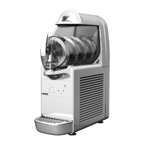
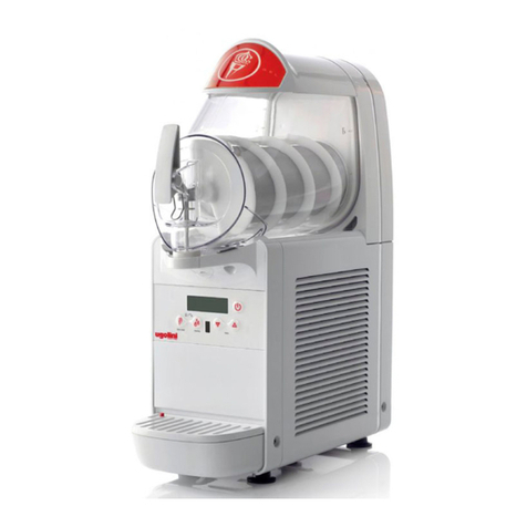
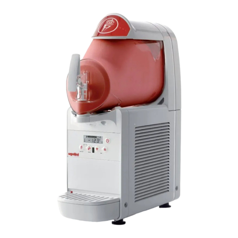
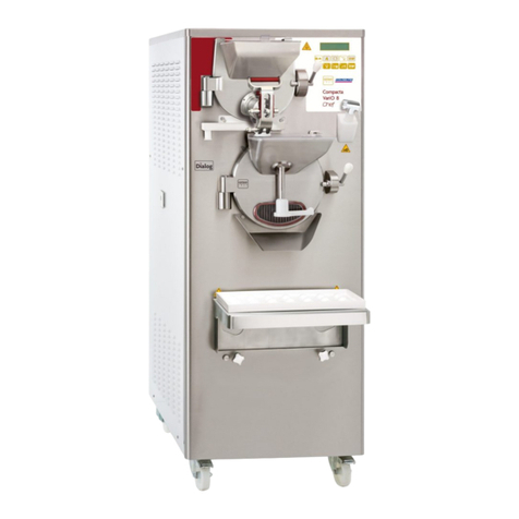
Ugolini NG 6 Series User manual

MANUALE D’ISTRUZIONE
OPERATOR’S MANUAL
CARNET D’INSTRUCTIONS
GEBRAUCHSANWEISUNG
MANUAL DEINSTRUCCIONES

14
1 ELECTRICAL SAFETY INSTRUCTIONS
1Before connecting the dispenser to the mains, check that
the voltage shown on the rating plate matches your electricity
supply. Connect the dispenser to a single-phase supply
through an earthed socket as required by current regulations. If
the dispenser is to be disconnected from the power supply
using a single pole switch, the gap between the contacts on this
switch must be sufficiently wide to guarantee full disconnection
under category III overload conditions.?
2Do not use extension cables to connect the appliance.
3To avoid any risks, if the power cable is damaged, it must
be replaced by the manufacturer, by an authorised technician
or by a similarly qualified person.
4The dispenser is not suitable for outdoor use.
5The dispenser must be installed in the upright position.
6Before cleaning, always disconnect the dispenser by
removing the plug from the socket.
7Always disconnect the dispenser before removing any of
the panels for cleaning or maintenance work.
8Do not use a water jet to clean the dispenser.
9This appliance must not be operated by children.
10 Do not let children play with the appliance.
11 This appliance must not be used by persons with reduced
physical, sensory or mental capabilities or with a lack of
experience and knowledge unless they have supervision or
have been trained regarding the safe use of the appliance and
understand the risks involved.
12 Only persons who know and have practical experience of
the appliance are permitted access to the inner components of
the dispenser, especially when dealing with issues regarding
safety and hygiene.
2 HYGIENIC SAFETY INSTRUCTIONS
1This appliance is intended exclusively for domestic and
similar use.
2For the appliance to operate correctly, room temperature
must be between +5° and +32°C.
3Use the appliance to cool the indicated liquids only.
4Do not introduce dangerous or toxic liquids to the appliance.
3 TECHNICAL CHARACTERISTICS
We reserve the right to amend this manual without notice.
4 INTRODUCTION
Read this instruction booklet carefully in order to familiarise
yourself with all aspects of the dispenser.
Like all mechanical products, this machine will require cleaning
and maintenance. Good operation can also be affected by any
errors made by the operator during disassembly and cleaning.
For this reason, in the case of daily operations such as
disassembly, cleaning, sanitising and reassembly, it is important
that the person using the dispenser is aware of the procedures
and can perform them without making errors.
5 INSTALLATION
1Remove the dispenser from the packaging, which you
should keep in case it is needed in the future.
2Check that the dispenser has not been damaged during
transport. If it has, make a report to the carrier immediately.
3Position the dispenser on a bench capable of supporting the
weight, even at full load, bearing in mind the IMPORTANT
Transparent removable bowls n 1 2 3 1 2 3
Capacity of each bowl, approx. l 6 6 6 10 10 10
Dimensions:
width cm 20 40 60 20 40 60
depth cm 50 50 50 50 50 50
height cm 62 62 62 70 70 70
Net weight, approx. kg 23 41 57 25 45 61
Gross weight, approx. kg 25 44 60 27 48 64
Hermetic compressor
Air-cooled condenser
Overload protector
Noise level lower than 70 dB (A)
IMPORTANT
Electrical characteristics: read the data on the plate of
each individual dispenser. This is located at the bottom
of the front panel, behind the drip tray on the right. The
serial numbers of the devices (preceded by the symbol #)
are shown on the frame below. Always refer to the data
shown on the plate.
IMPORTANT
When transporting or lifting the dispenser, never pick it
up by the transparent containers or the evaporator cylin-
ders. The manufacturer is not liable for damage caused
by such mishandling.
NG 6/1
NG 6/2
NG 6/3
NG 10/1
NG 10/2
NG 10/3

15
warning in point 1 above.
4Allow a minimum clearance of at least 15 cm all around the
dispenser so as not to impede the flow of cooling air.
5Check the stability of the device, adjusting the height of the
feet if necessary. In the event that the dispenser is provided
with a series of high feet (approximately 100 mm), these must
replace the original ones.
6The dispenser does not leave the factory pre-washed and
sanitised. Before use, it must be disassembled, washed and
sanitised, following the instructions in Chapter 7.4 CLEANING.
7If required by local regulations, it is possible to have the
appliance permanently connected to electrical power supply,
ref. National Electrical Code (NEC) and NFPA 70. If this is the
case , remove the terminal block and, if necessary, enlarge the
hole on the sheet base, to allow the conduit entry.
6 TO OPERATE SAFELY
1Do not operate the dispenser without reading this
operator’s manual.
2Do not operate the dispenser unless it is properly
grounded.
3Do not operate the dispenser unless all panels are
restrained with screws.
4Do not put objects or fingers in panels louvers and faucet
outlet.
5Do not remove bowls, augers and panels for cleaning or
routine maintenance unless the dispenser is disconnected from
its power source.
6The cover must be always closed.
7 OPERATING PROCEDURES
To remove the lid of the container, press the top key and slide
the lid towards the front of the container. If there is a safety lock
for the lid, turn the key in an anti-clockwise direction to release
the open key (see figure 6).
1Wash and sanitise the dispenser before using it, following
the instructions in Chapter 7.4.3 WASHING.
2Fill the container with the desired product, bearing in mind
that, during processing, the volume will increase. For this
reason, the containers must not be filled to maximum capacity.
To prepare granita, consider an increase in volume of around
10%.
3If using liquid or powder bases, specially prepared for
granita, follow the manufacturer's instructions carefully.
4If using natural products to prepare granita (for example
lemon juice, orange juice or coffee), dissolve 150-200 grams of
sugar in each litre of product.
5If using freeze-dried bases to be diluted with milk or water,
prepare the product in a separate container and only pour it into
th e ma c hi ne c o nt ai n er s af t er m ak in g su r e t ha t i t is
homogeneous and that the powder is well dissolved.
6Using the controls (see Chapter 7.1 DESCRIPTION OF
CONTROLS).
7The dispenser must operate without interruption: the
cooling system for each container will automatically stop when
the product is ready to be dispensed, maintaining the set
density. The mixing devices will still continue to operate.
7. 1 DESCRIPTION OF CONTROLS
The dispenser is equipped with a main switch together with a
keyboard and a screen for each bowl. These devices allow
setting the dispenser operation mode. The following modes are
available:
STANDBY: the dispenser is fed and it is ready to start.
GRANITA MAKING: the dispenser makes granitas according to
the product in the bowl.
PRODUCT PRESERVATION: the dispenser keeps the liquid
product at a suitable temperature for its preservation. This mode
can be usefully selected during the night, since it allows
maintaining the product quality while reducing energy
consumption.
WASHING: only the mixers work, the cooling system is stopped.
This mode can be usefully selected during the dispenser
washing.
MAIN SWITCH
The main switch is located under the dispenser, on the left side.
It has the following functions:
CONTROL KEYBOARD
figure 1
ATTENTION
Make sure the device is properly earthed, otherwise you
may cause electric shocks to persons or damage to the
dispenser.
IMPORTANT
Place the device in such a way that the power cable is
easily accessible.
IMPORTANT
In any case, once the mixture is obtained, its degrees
Brix (sugar content percentage) must be greater than 13.
Never use the machine with water only.
IMPORTANT
Use the dispenser with food products only.
Position 0 : the dispenser is off.
Position I : the dispenser can work but it is in Standby
mode. Only pilot light (A) is on.

16
The keys have the following functions:
The display shows the following icons, too:
HOW TO START THE DISPENSER
Turn the main switch to position I. Pilot light (A) will be on
showing that the dispenser is ready to work.
Keep key (B) pressed until the dispenser starts.
Select the operation mode and the desired product density by
means of keys (C) or (D).
7. 2 ADDITIONAL FUNCTIONS
LIGHT SWITCHING ON/OFF
By pressing key standby (B) twice quickly, lights can be turned
on and off. When the machine is in the Granita Making mode,
lights are always on; when the machine is in the Product
Preservation mode, lights are always off.
DENSITY ADJUSTMENT
When the machine is working in the Granita Making mode, it is
possible to adjust product density by pressing keys C or D
briefly.
The factory set value is 5, which is convenient to make granitas.
WASHING MODE
When the dispenser is in the Product Preservation mode, by
pressing key C for two seconds, the Washing mode is enabled.
In such a case, the mixer turns but cooling is disabled.
Use this mode during the machine washing and sterilization to
prevent the cleaning solution from cooling.
By pressing any key, the dispenser exits from the Washing
mode and returns to the Product Preservation mode.
ALARM DISPLAY
If a fault occurs during the dispenser operation, an alarm
message will be displayed. One of the elements on the density
bar will flash showing the corresponding alarm number. To find
a detailed alarm list, please refer to the Service Manual.
COMPRESSOR CONDITION
Element 1 of the density bar of the right bowl shows the
compressor operation condition:
KEYBOARD LOCK
It is possible to lock the keyboard to prevent access to the
dispenser controls by keeping keys C and D pressed together
for two seconds.
By pressing keys C and D at the same time again, the keyboard
is unlocked.
The smart display (optional) shows the following icons, too:
Pilot light A On the right bowl: if it is on, it indicates that
the machine is in Standby mode; if it is off, it
indicates that the machine is working; if it fla-
shes, it indicates that the right bowl only is
off.
On the left bowl: if it is off, it indicates that
the bowl is working; if it flashes it indicates
that the bowl is off.
Standby key B On the right bowl: if it is pressed for two
seconds, it allows turning on and off the
whole machine; if it is pressed quickly while
the machine is working, it allows turning on
and off a single bowl (on machines with mul-
tiple bowls only).
If it is pressed twice quickly: it allows turning
on and off the cover lights.
On the left bowl: if it is pressed quickly while
the machine is working, it allows turning on
and off a single bowl.
Product Pre-
servation Key
(C)
If it is pressed quickly, it allows increasing/
decreasing density. If it is pressed one
second while the machine is running in the
Granita making mode, it allows switching to
the Product Preservation mode. If it is pres-
sed one second while the machine is run-
ning in the Product Preservation mode, it
allows switching to the Washing mode.
Granita Making
key (D)
If it is pressed quickly, it allows decreasing
density. If it is pressed one second while the
machine is running in the Product Preserva-
tion mode, it allows switching to the Granita
Making mode.
If it is pressed one second while the machine
is running in the Granita Making mode, it
allows resetting possible alarms.
So le n o i d va lv e
icon (E)
It shows the condition of the cooling sole-
noid valve.
Icon off: solenoid valve closed
Icon flashing: delay timer on
Icon on: solenoid valve open
Product Preserva-
tion Icon (F)
If it is on, it shows that the machine is in
the Product Preservation mode.
Granita making
Icon (G)
If it is on, it shows that the machine is in
the Granita Making mode.
Density bar (H) It shows the set density value and the alar-
ms.
- Off: compressor off
- Flashing: start delay timer on
- On: compressor on
Solenoid valve
icon (E)
It shows the condition of the cooling sole-
noid valve.
Icon off: solenoid valve closed
Icon flashing: delay timer on
Icon on: solenoid valve open
Product Preserva-
tion Icon (F)
If it is on, it shows that the machine is in
the Product Preservation mode.
Granita making
Icon (G)
If it is on, it shows that the machine is in
the Granita Making mode.
Density bar (H) It shows the set density value and the alar-
ms.
Current time (L) Displays the current time and/or product
temperature.
°C/°F scale icon
(M)
temperature scale set (°C or °F).

17
TIMER
DAY/NIGHT TIMER
This control board has a clock module which is used to
automatically switch from day mode to night mode and
vice versa at preset times.
N.B. On machines with multiple tanks, the timer will only be
present on the master display board and its settings will apply
to all tanks.
When the machine is in Standby, the current time will be
displayed with two flashing points separating the second and
third digit to indicate the seconds.
The current time and the mode switching times can only be set
when the machine is in Standby mode using the following keys:
Setting of current time and temperature scale (°C / °F)Key B +
Key C
Setting of mode switching time intervalsKey B + Key D
Timer ON/OFF Key D pressed for 5 seconds
SETTING OF CURRENT TIME
Press keys B and C simultaneously to enter the current time
setting mode. Press keys C and D to make the individual
settings and press key B to conform and move on to the next
selection. The following must be set in this order:
1European or American way of displaying the current time.
The number 24 or 12 will be displayed and the second two
figures will flash.
2Setting of current time. The first two figures will flash as well
as the third or fourth figure if the American A/P clock is
selected.
3Setting of minutes. The second two figures will flash.
SETTING OF MODE SWITCHING TIME INTERVALS
Press keys B and C simultaneously to enter the switching time
interval setting mode. The setting will always start from 00:00
and the first time with the day mode, indicated by a lit G icon.
Press keys C and D to increase or decrease the time shown on
the display by intervals of 15 minutes and press key B to modify
the operating mode from day to night and vice versa. To adjust
the intervals, you must select whether the machine should be in
night or day mode at 00:00 by pressing key B and then press
key C until you reach the time you want to change mode. Now
press key B to switch mode and the icon will come on to
indicate that the mode has changed. Scroll backwards and
forwards using keys C and D to check the switching time
intervals. You can set mode switching for every 15 minutes.
When you reach 23:45 press key C again to quit the switching
time interval setting.
If the American clock (12 hr) has been selected, A or P will be
indicated on the third or fourth figure.
TIMER ON/OFF
If you press key D for 5 seconds when the machine is in
Standby mode, you can activate the day/night timer. The icon N
will indicate the state of the timer. The default value the first
time the machine is switched on is timer OFF.
N.B. The keypad lock also has affects the Standby mode and
therefore the possibility of adjusting the clock.
TEMPORARY SUSPENSION OF TIMER
When the timer is activated and the machine is operating in Day
Mode, the timer can be temporarily suspended so that the
operating mode can be manually adjusted. To do this, hold
down the night key for two seconds, the timer icon will flash and
you can select the Night Mode or Cleaning on any tank. Press
the day key again to reactivate the timer.
7. 3 OPERATION HELPFUL HINTS
1The time required to obtain the cooling of the product varies
depending on several factors such as the ambient temperature,
the initial temperature of the product, its sugar content (degrees
Brix) and fat content and the density adjustment.
2Topping up the containers with product that is already pre-
cooled further increases the efficiency of the dispenser.
3To further reduce recovery time and thus increase the
autonomy of the dispenser, fill up the tanks when the level of
product has fallen to the halfway point of the evaporator.
4To store the product correctly, the distributor must also
operate at night, at least in the PRODUCT STORAGE position.
5Night operation in the PRODUCT STORAGE position also
eliminates the possible formation of ice (due to condensation of
atmospheric moisture) on the outside of the containers.
6Never turn off the dispenser when there is product in the
containers. If not cooled, the product may deteriorate.
Furthermore, unless it is mixed, it may stick together and form
blocks of ice. If the mixer is restarted in these conditions
(without waiting for the ice to melt), the dispenser may be
damaged.
7All dispensers of this kind must emit heat. If, however, this
emission seems excessive, check that no source of heat is
located near the dispenser itself and, in particular, near the grid
panels. Also make sure that the airflow is not impeded by the
proximity of walls, boxes or similar. Leave at least 15 cm free
space around the dispenser. Finally, check that the filter
located below the rear panel is clean.
8The product is for use with confectionery only.
7. 4 CLEANING
1Cleaning and washing are essential to guarantee the
perfect preservation of the taste of the product and the
maximum efficiency of your dispenser. The procedures
described below should be considered general in nature and
may vary due to the health regulations in force.
2Before disassembly for washing, the dispenser must be
emptied out of the product. Proceed as follows:
- use the keypad to select the CLEANING operating mode
- if necessary, wait until the product becomes liquid
- remove the flow restrictor from the container (see figure 12)
- place a container under each tap and empty the containers
- fill the containers with water and allow the dispenser to
operate in CLEANING mode for a few minutes. Then empty the
containers.
- hold down key A to switch off the dispenser
- turn the ON/OFF SWITCH to OFF
7. 4. 1 DISASSEMBLING THE RECOVER (OP-
TIONAL)
1Place the right-hand part of the recover on a surface. Place
Timer icon (N) when this symbol is lit, the timer is opera-
ting.
ATTENTION
The access to the service area is restricted to persons
having safety/hygiene knowledge and practical expe-
rience on the appliance.

18
the container inside it.(see figure 2)(see figure 3).
figure 2
figure 3
2Put the left-hand part of the recover into position and make
sure that it fits into the illustrated groove. Click the two parts
together. (see figure 4)(see figure 5).
figure 4
figure 5
7. 4. 2 DISASSEMBLY
1To remove the lid of the container, press the top button and
slide the lid towards the front of the container.
If there is a safety lock for the lid, turn the key in an anti-
clockwise direction to release the open button (see figure 6).
figure 6
2To remove the container, push the lever upwards (see
ATTENTION
Before disassembling any component, always unplug
the device from the mains.

19
figure 7) and then remove the container itself (see figure 8).
figure 7
figure 8
3Remove the mixer by sliding it out of the evaporator
cylinder. Then remove the hexagonal joint (see figure 9).
figure 9
4Remove the gasket from its housing (see figure 10).
figure 10
5Disassemble the tap by following the order given (see figure
11).
figure 11
6Remove the drip tray and empty it.
7Remove the flow restrictor from the container (see figure

20
12).
figure 12
7. 4. 3 WASHING
1Fill a basin with approximately one gallon of hot water (45-
60°C) and sodium hypochlorite (bleach) at a ratio of 1
tablespoon per 2 litres of water; indeed, a solution that is too
concentrated may damage the parts to be washed, whereas
one that is too diluted may not clean properly. Do not use any
abrasive detergents.
2In order to avoid damaging the dispenser, only use
detergents that are compatible with plastic components.
3Wash the evaporator cylinder, the upper tank and the
connecting pipe using the brush supplied with the unit.
4Rinse all washed parts under running water.
7. 4. 4 SANITISING
Sanitising must be done immediately before starting up the
dispenser. Do not allow it to remain idle for a long time after
sanitisation.
1Before starting the procedures described below, wash your
hands with antibacterial soap.
2Pour about eight litres of a solution made of hot water (45-
60 °C) and sodium hypochlorite (bleach) at a ratio of 1
tablespoon per 2 litres of water.
3Immerse all parts to be sanitised in the solution for the time
indicated by the product manufacturer.
4Allow the sanitised parts to air dry on a clean surface.
5Dry the external parts of the dispenser without using
abrasive cloths.
7. 4. 5 REFITTING THE RECOVER (OPTIONAL)
1Click open the two parts. (see figure 13).
figure 13
2Remove the left-hand part and then the right-hand part of
the recover. (see figure 14)(see figure 15).
figure 14
figure 15
IMPORTANT
Do not wash any part of the machine in a dishwasher.
ATTENTION
Before any cleaning operation, always unplug the
dispenser from the mains or turn off the external wall
switch.
IMPORTANT
In order to prevent damage to the dispenser, use only
detergents that are compatible with the plastic parts.
ATTENTION
While washing the dispenser, do not use excessive
amounts of water around the electrical components. This
could cause electric shocks or damage to the dispenser.

21
7. 4. 6 ASSEMBLY
1Slide the drip tray into place..
2Lubricate the tap piston, the hexagonal joint and the mixer
at the points indicated in figure 16 (NG6) or figure 17 (NG10),
using only the grease that came with the machine or other
grease for use with food.
figure 16
figure 17
3Reassemble the tap on the container in reverse order
compared to that shown in figure 11.
4Replace the container gasket.
N.B. the rim with the greater diameter must be rested on the
rear wall (see figure 18).
figure 18
5Reassemble the hexagonal joint and then the mixer (see
figure 19).
figure 19
6Replace the container by pushing it towards the back wall,
making sure it fits properly onto the gasket. The locking lever
will be lowered until it rests on the drip tray surface (see figure

22
20).
figure 20
7Rinse using a cool beverage in order to eliminate any
remaining sanitising solution from the bottom of the containers.
Dry the inside of the containers with a disposable paper towel.
7. 5 IN-PLACE SANITIZATION
Sanitising the assembled device, prior to putting into
service, should only be performed, if necessary, as an
a d d i t io n a l p r e c a ut i o n t o t h e s a n it i s a ti o n o f t h e
disassembled devices described previously, never instead
of it.
1Prepare a solution of water and sodium hypochlorite
(bleach) at a ratio of 1 tablespoon per 2 litres of water.
2Pour the solution into the containers.
3Using a suitable brush, wipe the solution onto all parts
above the level of the solution and on the underside of the lid.
4Install the lid and operate the dispenser in order to allow the
solution to be stirred for about 2 minutes. Drain the sanitising
solution from the containers through the taps and then dispose
of it.
5Remove the flow restrictor from the container (see figure
12).
6Rinse using a cool beverage in order to eliminate any
remaining sanitising solution from the bottom of the containers.
Do not perform further rinsing.
8 ROUTINE MAINTENANCE
1Every day: inspect the dispenser and check for leaks of
product from the gaskets. If you notice leaks, first make sure
that the components of the dispenser are properly installed,
then check that the gaskets do not require lubrication and
finally that they are not worn or damaged. If they are, replace
them with original spare parts from the manufacturer.
2Every month: remove the dust from the condenser filter on
the back of the machine (see figure 21).
figure 21
3In case of noise it needs to unplug the cooler and call for
service.
4In case of failure unplug the machine, because unexpected
start again would be possible.
5It needs to fix everything back in the initial position after any
repairmen, like screws and covers.
8. 1 MAINTENANCE (TO BE CARRIED OUT BY
QUALIFIED SERVICE PERSONNEL ONLY)
Annually: Remove all the panels and clean the inside of the
machine including the base and the inside of the panels.
Never remove the anti-condensation material wrapped around
the evaporator outlet tube (the copper tube located to the right
of the geared motor). If said material is missing or lost, replace
with original spare parts from the manufacturer.
ATTENTION
Beware of the condenser fins as they are sharp.
IMPORTANT
"Product Preservation mode" is not to be used in lieu of
proper cleaning and sanitization procedures at the fre-
quencies required by the federal, state, or local regula-
tory agency.
IMPORTANT
In order to prevent damage to the dispenser, the plastic
parts must only be lubricated with the grease supplied by
the manufacturer or with another type of grease compati-
ble with plastic parts.
Other manuals for NG 6 Series
1
This manual suits for next models
1
Table of contents
Other Ugolini Ice Cream Maker manuals