UK POOL STORE UKPS16 User manual

UK POOL STORE FILTER PUMP PACK
INSTRUCTIONS
Available in the following Sizes:
UKPS16 – 16” Diameter Sand Filter & 0.35 Horse Power Pump – 6,000 Litres/Hour
UKPS19 – 19” Diameter Sand Filter & 0.75 Horse Power Pump – 9,000 Litres/Hour
UKPS24 – 24” Diameter Sand Filter & 1.0 Horse Power Pump – 11,400 Litres/Hour
SAND FILTER SYSTEM
SAFETY INFORMATION
1. The sand filters are designed to work with water at temperatures above 0°C and below
45°C. The filter should never be operated outside of these temperatures or damage may
occur.
2. The installation should be carried out in accordance with the safety instructions for
swimming pools and the specific instructions for each facility.
3. The user must ensure sure that the installation is carried out by qualified authorised
personnel and that all instructions are carefully read and followed. Incorrectly installed
equipment may fail, causing severe injury or property damage.

4. The safe operation of the filter is only guaranteed if the installation and operation
instructions are correctly followed.
5. To reduce the risk of injury, do not permit children to use this product.
6. Chemical spills and fumes can weaken your Swimming Pool or Spa, cause corrosion to filters
and other equipment failure, resulting in severe injury or property damage. Do not store
pool chemicals near your equipment.
7. Any modification of the filter requires the prior consent from the supplier and original
replacement parts and accessories authorised by the manufacturer, to ensure a high level of
safety.
Sand Filtration working principle
Incoming water from the swimming pool piping system is automatically directed by the
Multiport Valve to the top of the filter bed and filtered out. The filtered water is returned from
the bottom of the filter tank, through the Multiport Valve and back through the swimming pool
piping system.
Preparation before installation
1. Position the filter as close to the Swimming Pool/Spa as possible.
2. The filter should be placed on a level concrete slab, very firm ground or the equivalent.
Ensure that the ground will not subside, preventing any strain on the attached plumbing.
3. Position the filter so that it does not compromise the piping connections, ensuring
convenient operation and servicing.
4. Ensure that the compliance label is facing the front to allow easy identification in the case of
service difficulties.
INSTALLATION OF FILTER TANK
1. Place the filter tank on the base, locate the two front lugs at the foot of the filter into the
base first, then lower the filter flat onto the back of the base. Then simply twist the tank
clockwise to locate the four lugs fully home into the base slots (see fig 1.) If installed
correctly you should not be able to lift the tank off the base at this point. Please ensure you
position the outlet drain plug so that it is facing front and centre for ease of operation.
Fig. 1

2. Before filling the filter vessel with the filter media, install the laterals, this has to be done
from inside the tank as the assembly cannot be built outside of the filter. simply match the
raised point at the end of each lateral (see fig 2.) to the raised point on the lateral hub.
Insert the laterals and turn 90°clockwise, you should hear the lateral click into place. Repeat
until all laterals are fitted.
Fig. 2
3. Check the air release hose is fixed securely onto the body of the lateral holder with the
other end out of the sand – DO NOT bury the air release hose in the sand, it must be free to
sit on top of the final filled level.
4. To eliminate stress during the sand filling on the laterals, fill the filter vessel with enough
water to provide a cushioning effect when the filter sand is poured in (12”).
5. In the packaging you will find a flimsy clear sand filling ‘Top Hat’. This is vital in ensuring the
filters internal pipe is perfectly located & central before filling with sand. The ‘Top Hat’ will
prevent any sand from dropping into the centre pipe, it is a clear indication that the centre
pipe is fully down into the filter.
6. Carefully pour the sand into the filter vessel. Ensure that no sand enters the stem pipe and
that no damage occurs to the laterals. Continue filling the filter until the correct charge has
been installed (see chart for sand fill charges).
7. Remove the ‘Top Hat’ and wash any debris off the filter top mount, put the O Ring on the
top mount multiport valve and with a twisting pushing action fit the valve onto the filter
centre pipe until fully home. Assemble to two half flanges together to connect the filters top
lid and multiport flanges within the clamp and lightly tighten equally. Do not fully tighten
until you are satisfied that the multiport is in the correct alignment to ensure a straight
connection to the pump.
8. Using screws from the pump hardware pack fix the pump to the base. Please refer to pump
installation guide for operating instructions.
9. Adjust the valve position and using the white pressure hose(ensuring you fit the ‘O’ rings),
connect the pump output to the top mount valve. (“TO PUMP” is embossed on the curved
plastic input of the multi port valve to easily identify the correct port).
10. There are two remaining connections to the valve – one is connected to the pool (marked
“TO POOL”) the other connects to the drain outlet hose, which is also easily identified with
the sight glass.

INSTALLATION NOTES
1. Ensure the filter is working correctly under normal working pressure (between 15 and 20
psi).
2. If the pump is positioned higher than the water level, it will be necessary to install a back
water control valve or check valve.
3. If the pump is positioned lower than the water level, it will be necessary to install an
isolation valve or double union ball valve.
4. Avoid excessive bending of adaptors and hoses which will cause reduction in water flow.
5. Do not over tighten fittings or adaptors.
INSTRUCTIONS ON USE:
1. Ensure the pump is turned OFF
2. Inspect and ensure that all connections are correct and secure.
3. Depress top mount valve handle and rotate to BACKWASH position.
4. Prime and start pump according to pump instructions.
NOTE: ALL SUCTION AND DISCHARGE VALVES MUST BE OPENED WHEN STARTING UP THE
SYSTEM. FAILURE TO DO SO COULD CAUSE SEVERE PERSONAL INJURY.
ENSURE THE PUMP STRAINER BASKET IS FULL OF WATER BEFORE STARTING THE PUMP.
FAILURE TO DO SO WILL CAUSE DAMAGE TO THE PUMP AND INVALIDATE YOUR WARRANTY.
5. Once the water flow is steady from the waste line, run the pump for 2 minutes. This initial
backwash of the filter is recommended to remove any possible impurities and fine sand
particles evident in the filter media.
6. Turn pump OFF and set valve to RINSE position. Turn pump ON and run until the water in
sight glass is clear – about ½ to 1 minute. Turn pump OFF, set valve to FILTER position and
restart pump. Your filter is now operating in the normal filter mode, filtering particles from
the pool water, and returning fresh clean water back into your pool.
NOTES:
1. Make a note of the initial pressure gauge reading when the filter is clean (It will vary from
pool to pool depending upon the pump and general piping system). As the filter removes
dirt and impurities from the pool water, the accumulation in the filter will cause the
pressure to rise and the flow to diminish. When the pressure gauge reading is 4 – 6 PSI
higher than the initial “clean” pressure you noted, it is time to backwash (clean) the filter.
2. IMPORTANT: To prevent unnecessary strain on the piping system and valves, ALWAYS shut
OFF the pump before switching filter control valve positions.
3. To prevent damage to the pump and filter and for proper operation of the system, clean the
pump strainer and skimmer baskets regularly.
SAND FILL GUIDE:
UKPS16 – 16” Diameter Sand Filter & 0.35hp Pump requires 45kg of 16/30 filter media.
UKPS19 – 19” Diameter Sand Filter & 0.75hp Pump requires 75kg of 16/30 filter media.
UKPS24 – 24” Diameter Sand Filter & 1.0hp Pump requires 136kg of 16/30 filter media.

FILTER CONTROL VALVE FUNCTIONS
Filter-
FILTER – Set valve to FILTER for normal filtering. Also use for regular vacuuming.
Backwash-
BACKWASH – For cleaning filter sand. When filter pressure gauge rises 4-6 PSI above start-up (clean
pressure): Stop the pump, set valve to BACKWASH. Start pump and backwash until water in sight
glass is clear. Approximately 2 minutes or less depending on dirt accumulation. Proceed to RINSE.
Rinse-
RINSE – After backwashing, and with pump OFF, set valve to RINSE. Start pump and operate for
about ½ to 1 minute. This ensures that all dirty water from backwashing is rinsed out of the filter to
waste, preventing possible return to the pool. Stop pump, set valve to FILTER and start pump for
normal filtering.
Waste-
WASTE – To bypass the sand filter for draining or lowering water level and for vacuuming heavy
debris or very fine dusty particles directly to waste.
Re-circulate-
RE-CIRCULATE: Water is re-circulated through the pool system, bypassing the sand filter.
Closed-
CLOSED – Shuts off flow from pump to filter.

COMBINATION PUMPS
GENERAL SAFETY RULES
1. The products mentioned in this manual are specially designed for the pre-filtering and re-
circulation of water in swimming pools and spas.
2. They are designed to work with clean water at a temperature not exceeding 40℃.
3. The installation should be carried out in accordance with the safety instructions of
swimming pools.
4. During operation, some parts of the pump are subject to dangerous electric voltage. Work
may only be performed on each pump or on the equipment connected to it after
disconnecting them from the main power and after disconnecting the starting device.
5. The user should ensure that assembly and maintenance tasks are carried out by qualified
authorised persons and that these persons have first carefully read the instructions for
service and installation.
6. The operating safety of the pump is only guaranteed if the installation and service
instructions are correctly followed.
7. The limit values stated in the technical table should not be exceeded under any condition.
8. In the event of defective operation or fault, contact the technical support department of the
manufacturer or their nearest authorised agents.
9. If the supply cord is damaged, to avoid hazard, it must be replaced by the manufacturer or
its service agent or a similarly qualified person.
10. The pump must be supplied through a residual current device (RCD) having a rated residual
operating current not exceeding 30mA.
11. Children should be supervised to ensure that they do not play with the appliance.
12. The pump must be protected from running dry.
LOCATION
The pump must be located as close as is practical to the pool. The pump must also be in a position
that enables easy access for periodic servicing.
Care must also be taken to position the pump in an area that is free from flooding and in a well
ventilated and dry area.
INSTALLATION
We have adopted the latest technology when designing and manufacturing our pumps, a few simple
precautions during installation will ensure years of trouble free operation.
1. The pump suction line should not be smaller than 1½” (40mm imperial) or 50mm true
metric.
2. The suction line should have as few bends or elbows as possible. There must not be any air
traps on the suction line.
3. Installation should be arranged on a solid, flat foundation with the pump bolted securely to
it.
4. The pumps electrical cable must be wired for the proper voltage and current in accordance
with the wiring instructions.
5. All wiring (electrical) work must be carried out by licensed electricians and must be installed
in accordance to the local codes.
6. The motor must be earthed.
7. The weight of the plumbing and fittings should be supported and not carried by the pump.
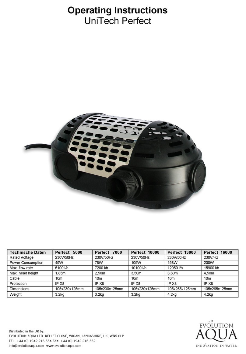
8. The maximum total head (Hmax) of the pump (in metres) shown on the pump label should
be noted by the installer.
9. The permissible temperature is + 0℃and - 40℃. The pump should never be operated
outside of these temperatures, to do so could cause damage.
ELECTRICAL CONNECTION
Check that the information on the nameplate corresponds to the power supply.
Employ a competent electrician to ensure wiring installation is made in accordance with any local
electrical codes. Every motor requires either a fused disconnect switch or a circuit breaker.
A SINGLE PHASE MOTOR has a built in thermal overload switch.
PUMP WATER PRIMING
The pump will prime and re-prime providing the pump basket area is full of water and there is
sufficient supply from the suction point. If you lose water from the pump basket area it will be
necessary to re-fill it before starting.
1. Remove the translucent lid and fill the pump basket with water.
2. Replace the lid ensuring that the O ring is correctly located and start the pump.
After you have done this allow a few minutes (maximum) running for the pump to re-prime. If
this fails then simply repeat the priming procedure.
WARNING:
Mechanical seals will be rapidly damaged and may need replacing if the pump is run dry – this
is not a warranty condition.
ENSURE that there is always adequate water in the pump basket before you start up.
If you are unable to prime the pump, please see the trouble shooting guide.
ENSURE that all suction and discharge valves are open before you start the pump, avoiding
resultant damage to the pump.
MAINTENANCE
The strainer basket in the pump should be inspected and cleaned at regular intervals.
1. Remove lid and lift out basket.
2. Remove debris and hose off with clean water if necessary.
3. Inspect the lid gasket, lubricate with SILICON based grease such a magic lube, only if needed.
4. Replace the strainer.
5. Re-prime the pump basket area.
6. Correctly locate the O-ring.
7. Replace the lid (hand tighten only).
8. Switch on the pump.
In climates where the pump may be exposed to frost or freezing, care must be taken to ensure
the pump is protected from frost damage.
It is recommended that if the pump is not used during winter periods it should be drained
completely and stored in a dry location. Do not replace the drain plug but store it in a safe place
when not in use; for example, the pump basket.

When you re-activate the pump, ensure all seals and O rings are in operational condition, re-
grease if necessary and replace if unsure of condition.
Check that the motor shaft moves freely before re-activation.
TROUBLE SHOOTING
SYMPTOMS PROBABLE CAUSE WHAT TO DO
Pump will not prime Suction air leak Make sure water level is correct
through suction points. Ensure
baskets and strainers are debris free
Tighten all fittings/unions on the
Suction side of the pump, remove
and replace mechanical seal.
No water in the pump Make sure the filter tank is full.
Closed valves or blocked Open all valves in system, clean
lines. skimmer and pump basket, check
pump impeller for blockage.
Motor will not run No power to motor Check that all electrical switches are
on. Ensure the circuit breakers are
properly set. Check if timer is
properly set. Check motor wiring
at the terminals.
Pump jammed. With power switched off turn pump
shaft (should spin freely).
Low Flow Dirty Filter Backwash or clean cartridge.
Dirty skimmer and pump Clean skimmer and pump
Strainer strainer.
Motor runs hot Low or incorrect voltage Supply to be corrected by
electrician.
Motor running too hot to touch
is normal. Thermal overload
protector will function to turn them
off if there is an overload or an
excessively high temperature
problem.
Installed in direct sunlight Shield from weather.
Poor ventilation Do not tightly cover or enclose
motor.

Noisy Pump Operation Bad bearing Replace by electrician.
Air leak in suction See 1
Suction blockage Locate and clear blockage
Disturbance in impeller Contact Supplier
Cavitations Improve suction, reduce suction
lift, reduce number of fittings,
increase pipe size, increase
discharge pressure and reduce flow
By throttling discharge valve.
Motor overload cuts Motor not connected Have electrician check wiring.
properly
Low income voltage Voltage at motors should be no
more than 6% above or below
nameplate voltage. Have electrician
check voltage, ensure pump is not
running on an extension cord.
Report low supply to authorities.
Overload due to binding Contact Supplier
in pump or wrong size impeller
WARNING
If the pump is within the stated warranty period and you experience faults, always contact your
supplier. Failure to do this may void warranty. Refer to warranty documentation supplied with the
pump. All electrical work is carried out by a Qualified Electrician; under no circumstances should you
attempt repairs on the electrical components of pumps unless you are qualified to do so.
This manual suits for next models
2
Table of contents
Popular Swimming Pool Pump manuals by other brands

Davey
Davey SilensorPRO SP200BT Installation and operating instructions

Sunrunner
Sunrunner SUNC3000 40885 Operation manual

Theralux
Theralux Theratherm User and service manual

STA-RITE
STA-RITE JWPA5C owner's manual

Viron
Viron P280 eVo Installation and operating instructions

Aqua
Aqua APB075PRO owner's manual