Ultrasound Technologies PD1 series User manual

&
Ultrasound Technologies
Operating Instructions
PD1+
fetal pocket doppler with FHR display
PD1
fetal pocket doppler

INTRODUCTION
The UltraTec PD1 and PD1+ are Pocket Doppler fetal heart
detectors designed to suit the needs of the General Practitioner
or Midwife for routine antenatal heart rate detection.
The PD1 is a dedicated fetal heart detector with integral 2 MHz
transducer and audio presentation of the fetal signal.
The PD1+ adds digital fetal heart rate detection and rate
display to the PD1 and is supplied with an integral 2 MHz
transducer. The built in loudspeaker provides audio
presentation of the fetal signal and the fetal heart rate (FHR) is
displayed on the LCD display. The PD1+ also has an RS232
data port for the transfer of data to a PC to review the fetal
heart rate traces.
The instrument is supplied complete with the following:
Doppler Instrument with integral 2MHz transducer
9V battery (6LR61)
Operating instructions
Coupling gel 0.25ltr
Soft carry case
The following symbols have been used on the instrument and
are defined according to
BS EN 60601-1:2006
Type B Equipment, Unit Classification
Unit On/Off control
Attention. Consult accompanying documents
This symbol on the product or its packaging indicates that
this product must not be disposed of with your normal waste.
WEE Directive (2002/96/EC)
Before using your Pocket Doppler for the first time, please read
these operating instructions carefully.
1

CONTROLS AND INDICATORS - PD1
The PD1 is powered from a single 9 volt alkaline battery (type
6LR61). To insert or change the battery, slide off the battery
cover (A) and withdraw the battery and connector. Carefully
remove the battery from the connector and snap the new
battery into position taking care to ensure correct orientation.
Place the battery and connector back into the battery
compartment and refit the battery cover.
To switch on the PD1 press the switch located on the front of
the PD1 unit (B).
The PD1 will stay on for approximately 5 minutes or until the
on/off switch is pressed again.
With the unit on, the volume can be adjusted by the rotary
volume control on the edge of the unit, (D).
The fetal heart signal is detected using the 2MHz fetal
transducer (E).
A Yellow LED (C) indicates the condition of the battery, when
illuminated constantly, battery replacement is recommended.
The LED will flash momentarily when the unit is first turned on.
2
Headset connector Battery low indicator (C)
Volume control (D)
2 MHz Fetal probe (E) Battery compartment (A)
Unit On / Off control (B)

CONTROLS AND INDICATORS - PD1+
The PD1+ operates in a similar manner to the PD1.
The unit is turned on by pressing the on / off control (B), the
system micro-controller monitors the detected signal and turns
the unit off when no signal has been detected for approximately
2 minutes.
The LCD displays battery condition and fetal heart
rate (F). A battery icon (C) is displayed when the battery
requires changing. The fetal pulse icon (G) flashes at
approximately the same rate as the
detected fetal heart.
Serial RS232 connection can be made by attaching the
optional serial link cable to socket (H) - contact supplier for
further details.
3
Headset connector
Fetal pulse icon (G)
Fetal heart rate display (F)
Battery low icon (C)
Volume control (D)
2 MHz Fetal probe (E) Battery compartment (A)
RS232 interface
connection (H)
Unit On / Off
control (B)

SPECIFICATIONS
Ultrasound
Frequency: 2 MHz continuous wave
Transducer: 2 crystal narrow beam
Output Power: <10mW/cm2SATA
Audio Response: 300Hz – 1KHz
Fetal Heart Rate: Multipoint real time Autocorrelator
(PD1+ only)
Unit Controls
Keys: 1 Key (for unit on / off)
Controls: Rotary volume
Indicators: PD1 Yellow battery low LED
PD1+ 3 digit FHR LCD display,
Battery low icon and FHR pulse icon
Power Supply
Battery: MN1604 (PP3) 9V Alkaline Manganese
Expected battery life: > 9 hours of use PD1
> 5 hours PD1+
Output
Headset: Audio output to optional headset.
Serial: (PD1+only) RS232 interface to optional
UltraTrace 2 PC software
Enclosure
Material: ABS
Size: 150mm by 75mm
Weight: 290gms typical
Safety
Classification: Type B - IEC 60601-1:2006
The following Consumables are available for use with
the PD1, PD1+
Coupling gel 0.25ltr
Alkaline battery (6LR61) 4
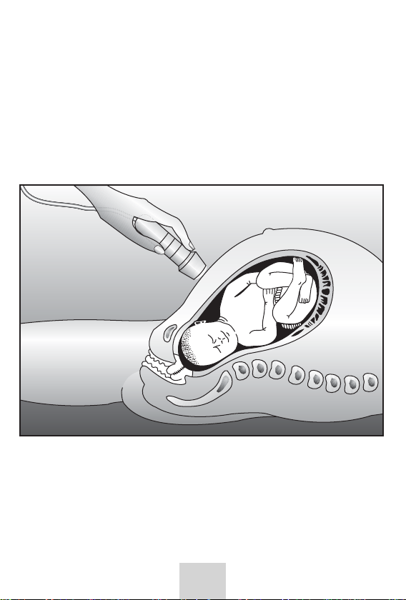
FETAL HEART DETECTION
The PD1 / PD1+ can be used to detect the beating fetal heart
from approximately the 10th week of gestation, though this will
vary between patients.
Apply a liberal amount of coupling gel to the area just above
the symphysis pubis and position the transducer face flat
against the abdomen. Tilt the transducer slowly until the fetal
heart is heard in the loudspeaker or headset (in early
pregnancy the headset helps to eliminate ambient noise
making it easier to detect the weaker signals).
Later on in pregnancy the best signals are generally found
higher up the abdomen. The same procedure should be
adopted as above.
Avoid sliding the transducer over the abdomen as this results in
an increase in the background noise and makes it more difficult
to detect the fetal heart sounds.
5

PLACENTA AND UMBILICAL CORD
The PD1 / PD1+ may be used to locate the position of the placenta,
thus aiding in the early diagnosis of placenta praevia or
eliminating placental site where amniocentesis is to be performed.
The sound from the placenta is an indistinct swishing, caused
by bloodflow in many vessels. There is no distinct beat pattern
to the sound.
The vessels of the umbilical cord give rise to a higher pitched
sound than the normal fetal heart, with pulsations at the fetal rate.
PD1+ FETAL HEART RATE RECORDING
The optional UltraTrace2 software runs under Windows XP
and provides a fetal monitor style real time chart recording
and patient database where the traces can be printed on
most Windows supported printers.
Details of the use of UltraTrace2 are included in the
UltraTrace2 operating manual.
For more information contact your supplier.
CARE OFYOUR PD1 OR PD1+ DOPPLER
After each use carefully wipe excess coupling gel from the
transducer with a soft tissue. Never use alcohol or any other
solvent to clean any part of the Pocket Doppler, as these may
cause damage. If cleaning becomes necessary wipe the
Pocket Doppler with a damp cloth moistened with a mild
detergent.
The transducer face is very delicate and may be damaged by
dropping. Always clip the transducer in its holder when not in use.
WARNINGS
PD1 series pocket dopplers are not to be used in the presence
of flammable anaesthetics, flammable gases or in an oxygen
rich environment.
If in any doubt of the Fetal Heart Rate from the PD1 series
pocket dopplers always use another method to establish the
well being of the Fetus. 6

SIMPLE FAULT FINDING
In the unlikely event of instrument failure, the following simple
checks may be made before contacting your supplier for further
advice.
Turn the volume control to maximum.
Turn the unit on and observe the Battery Low indicator, if it
does not illuminate, replace the battery and try again.
If the Battery Low indicator remains on, replace the battery and
try again.
If the Battery Low indicator illuminates and then goes out
(normal operation) stroke the transducer face.
If no audio signal is heard in the loudspeaker consult your
supplier.
When contacting your supplier with a problem please have
available the instrument type and serial number. The serial
number can be found inside the battery compartment.
SERVICE
A service manual for this equipment, which includes circuit
diagrams, parts lists and test procedures, is available and may
be purchased from your supplier or directly from Ultrasound
Technologies Ltd.
WARRANTY
Your PD1 Pocket doppler is guaranteed for a period of 3 years
against defects in material and workmanship. Any instrument
that proves to be defective within that period will be repaired or
replaced free of charge, provided that:
i) the instrument has not been damaged accidentally
or by misuse or mishandling.
ii) no unauthorised attempts at repair have been made.
iii) the goods are returned to Ultrasound Technologies
Ltd or its authorised representative freight pre-paid.
7

Under no circumstances whatsoever shall Ultrasound
Technologies Ltd have any liability for loss or for any indirect or
consequential damage.
This Equipment complies with the essential
requirements of the European Council
0120 Directive 93/43/EEC + 2007/47/EC
Manufactures Declaration and Guidance.
Electromagnetic Emissions and Immunity
Electromagnetic Emission
The PD1 series pocket doppler is intended for use in the
electromagnetic environment specified below. The User of the
PD1 series doppler should assure that it is used in such an
environment.
Emission Test Compliance Electromagnetic Environment
RF emissions Group 1 The PD1 series pocket doppler
CISPR 11 uses RF energy only for its internal
function. Therefore its RF
emissions are very low and are
not likely to cause any interference
in nearby electronic equipment.
RF emissions The PD1 series pocket doppler
CISPR 11 Class B is suitable for use in all
Harmonic Not establishments including
emissions Applicable domestic establishments and
IEC 61000-3-4 those directly connected to the
public low-voltage power supply
Voltage Not network that supplies buildings
fluctuations/ Applicable used for domestic purposes.
flicker
emissions
IEC 61000-3-3 8

Electromagnetic Immunity
The PD1 series pocket doppler is intended for use in the
electromagnetic environment specified below. The User of the
PD1 series doppler should assure that it is used in such an
environment.
Immunity Test IEC 60601 Test Level Compliance Level
Electrostatic ±6KV contact ±6KV contact
Discharge (ESD) ±8KV air ±8KV air
IEC 61000-4-2
Electromagnetic Environment - guidance
9
Floors should be wood, concrete or ceramic tile. If the floor is
covered in synthetic material the relative humidity should be
at least 30%
Electromagnetic Environment - guidance
d=1.2√P (80MHz to 800MHz)
d=2.3√P (800MHz to 2.5GHz)
Portable and mobile RF communications equipment should be
used no closer to any part of the PD1series pocket doppler,
including cables, than the recommended separation distance
calculated from the equation applicable to the frequency of the
transmitter.
Immunity Test IEC 60601 Test Level Compliance Level
Where P is the maximum output power rating of the
transmitter in watts (W) according to the transmitter
manufacturer and d is the recommended separation distance
in meters (m). Field strengths from fixed RF transmitters, as
determined by an electromagnetic site survey, ashould be
less than the compliance level in each frequency range b.
Interference may occur in the vicinity of
equipment marked with the following symbol:
Radiated RF IEC
61000-4-3 3V/m 80MHz to
2.5GHz 3V/m
Other manuals for PD1 series
1
This manual suits for next models
1
Table of contents
Other Ultrasound Technologies Medical Equipment manuals

Ultrasound Technologies
Ultrasound Technologies Fetatrack 310 User manual

Ultrasound Technologies
Ultrasound Technologies PD1 series User manual

Ultrasound Technologies
Ultrasound Technologies Freeplay FHRM User manual

Ultrasound Technologies
Ultrasound Technologies PD1+ combi User manual

Ultrasound Technologies
Ultrasound Technologies PFM1 User manual


