Underground Magnetics Mag 6 User manual


1: Introduction………………………………………...…….1
2: Caution………………………….…………………...……2
3: System Highlights…………………………………...….6
4: Receiver……………………………….………………….7
4.1: Specifications…………………………….....…...7
4.2: Receiver Operation………………………..….…7
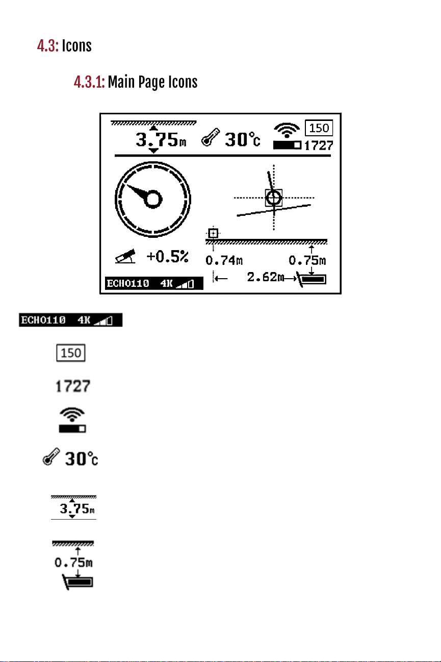
4.3: Icons………………………………………………8
4.3.1: Main Page Icons……………..…………8
4.3.2: Secondary Page Icons……………..…10
4.3.3: Calibration and
Depth Forecast Page Icons………….11
4.3.4: Setup Page Icons……………………..11
4.4: Calibration……………………………………....12
4.4.1: Depth Calibration…………………..….12
4.4.2: Roll Calibration…………………….…..13
4.5: Operation…………………………………..……14
4.5.1: Depth Prediction.………………...……14
4.5.2: Transmitter Activation…………………16
4.5.3: Transmitter Settings……………..……17
4.5.4: Receiver Settings………………...……18
4.5.5: Radio Channel Selection………..……19
4.5.6: Pairing…………….……………….……20
4.5.7: Pitch Unit Selection…………….……..21
4.5.8: Time Setting……………………………23
4.5.9: System Unlock…………………….….24
4.5.10: Visibility Control………………………25
4.5.11: Speed Control………………………..
4.6: Receiver Maintenance…………………………
1
2
3
3
3
4
5
5
7
8
8
9
9
10
11
11
12
13
14
15
16
17
18
19
20
21
22

5: Display…………………………………….………..……27
5.1: Specifications……………………………...……27
5.2: Display Operations………………………..……27
5.2.1: Down Hole Echo Mode Change…….
5.2.2: Radio Channel Selection…….…….…30
5.2.3: Pairing…………………………….….…31
5.2.4: Pitch Unit Selection……………………32
5.2.5: Distance Unit Selection……………….33
5.2.6: Visibility Control………………………..34
5.3: Display Maintenance…………………….…..…35
6: Transmitter…………………………….……………..…36
6.1: Introduction………………………………...……36
6.2: Specifications……………………………...……36
6.3: Digital Information………………………..….….37
6.4: Transmitter Maintenance………………………37
7: Locating Methods………………………………...…38
7.1: Locating Basics…………………………………
7.1.1: Three Point Locating……….……....
7.1.2: Single Point Locating……………….
7.2: Bore-To…………………...………..………...…
8: Battery and Charger……………………...……...……56
9: Warranty………………….…………….…....…………56
23
23
23
24
26
27
28
29
30
31
32
32
33
37
37
38
38
38
40
41
42
42

The MAG 6 & 8 are locating systems designed to assist
horizontal directional drill machine operators in locating
and tracking underground drill head locations and
orientations. The system consists of a transmitter, a
receiver, and a remote display.
These locating systems also offer four channel license
free radio telemetries between the receiver and remote
display. The user can easily “pair” any two receivers and
displays so that communications between the “pair” will
not be interfered by other “pairs”.
This manual is intended to provide information and
instructions on how to use these locating systems
properly. Underground Magnetics Inc. (UM) reserves the
right to improve the locating systems and the Operator’s
Manual at any time without notice.
The transmitter sends digital information of the
transmitter’s pitch, roll, temperature, and battery status
through an FM modulated RF signal.
The receiver receives this information and uses RF
signal to identify the transmitter’s status and location.
The receiver transmits the locating information to a
remote display through a radio telemetry system. A
horizontal directional drill machine operator can use
the information from the display to guide the drill head
to the desired path.
Page 1

The operator must understand safety procedures
and correct operation methods before operating the
HDD and the locating system.
HDD machines can cause property damage and
personal injury upon striking underground power
lines, gas lines, phone lines, television cables, fiber
optic cables, or sewage lines. Make sure to confirm
and mark all underground utilities before beginning
operations.
Do not use the locating system near flammable or
explosive substances.
Wear proper personal protective equipment
including steel-toed boots, safety gloves, helmets,
reflective vests, and safety goggles.
Obey all local safety regulations.
This locating system is only a tool to assist the
operator to locate the drill head. It is the operator,
not the Mag locating system that is responsible for
identifying the drill head location. UM is not
responsible for any damage or loss caused by using
the Mag system. Operators should operate the Mag
system according to the manual.
If there are any questions, please contact
Underground Magnetics.
Page 2

High precision and high anti-interference Faraday
shield 3D antenna structure
Industrial rated, gold-plated electronic modules
High-performance DSP
Dual locating system, functioning as two receivers
independently tracking to provide better accuracy and
reliability
Up to 110m depth range and up to 120 hours
continuous usage
11 System frequencies
4kHz –31kHz
Water resistant
IP65
Temperature range
-20° to 60°C
Telemetry
4 radio channels with range
up to 0.9km (900m)
Rechargeable lithium
battery
12.5V
Battery life
Up to 50 hours
Dimensions
68.5cm * 13cm * 30cm
Weight
3kg
Compatibility
XNeedle-M, Echo 1, Echo 2S, Echo 50,
Echo 60, Echo 70, Echo 90, Echo110
Mag 8
Page 3

Power key: Press and hold to turn on or off.
Tap to turn backlight on or off.
Up key: Move to previous cursor selection.
Down key: Move to next cursor selection.
Confirm key: Tap to confirm cursor selection.
Press and hold to enter secondary
page. Tap from main page to enter
Bore-To mode.
Setup key: Tap to enter calibration page/
return to main page. Press and
hold to enter setup page
11 System frequencies
4kHz –31kHz
Water resistant
IP65
Temperature range
-20° to 60°C
Telemetry
4 radio channels with
range up to 0.9km (900m)
Rechargeable lithium
battery
12.5V
Battery life
Up to 50 hours
Dimensions
68.5cm * 13cm * 30cm
Weight
3kg
Compatibility
XNeedle-M, Echo 1, Echo
2S, Echo 50, Echo 70
Page 4
Mag 6

•Transmitter model, frequency, and power
•Noise
•Signal strength
•Visual representation of signal to noise
•Transmitter temperature (Flashing
indicates transmitter is over-heating)
•Direct distance between transmitter and
receiver
•Vertical distance between receiver and
transmitter
Page 5

Page 9
•Estimated horizontal distance between
transmitter and receiver
•Estimated transmitter depth
•Transmitter pitch
•Roll indicator
•24 clock positions
•Single Point: direction of transmitter
•Locate Line
•Receiver
Page 6

To enter Secondary Page part I, press and hold .
To enter Secondary Page part II, tap from Secondary
Page part I.
Page 7
Transmitter model, frequency, and power
Receiver battery status
Radio channel
Battery voltage
Antenna voltage:
Normal range: 95% - 105%
Antenna power:
Normal power mode: 500mW –800mW
High power mode: 2000mW –3000mW

A1:3m calibration
A2: 10m calibration
A4:20m calibration
A5: Depth forecast
B1: Transmitter activation
B2: Transmitter settings
B3: Receiver settings
B4: Radio channel
selection
B5: Receiver and display
pairing
B6: Roll calibration
B7: Pitch unit selection
B8: Time & date setting
B9: System lock/unlock
B10: Visibility control
B11: System info
B16: Speed Control
Page 8

Warning: Even if the transmitter’s roll, pitch, battery status and
temperature are displayed correctly, calibration may not be
reliable due to a distorted magnetic field. Always do the
3m calibration first.
1. Make sure that the transmitter is
working properly. Place it in the
housing.
2. Place housing containing the
transmitter in a location away
from interference.
3. Set transmitter and receiver 3m, 10m, or 20m apart
from center of transmitter to inside edge of receiver’s
base, as shown.
4. Tap to enter
Calibration Page.
5. Tap and to highlight
desired distance for
calibration. Tap three times
to start calibration and wait for
calibration to complete.
6. Calibration complete.
7. Tap to return to Main
Page.
Page 9
3m, 10m,
20m

1. Place transmitter housing in a
12 o`clock position.
2. Press and hold to
enter Setup page and
tap to select B6
icon.
3. Tap three times to
enter and start roll
calibration and wait for
calibration to complete.
4. Calibration complete.
5. Tap to return to
Main Page.
Page 10

1. Tap to enter
calibration page and
tap to select A5
icon.
2. Tap to enter
Depth Forecast
Page.
3. Tap to return to
Main Page.
Note: The highest depth forecast value
is a conservative value and will
be the main value used when
determining interference.
Page 11
Tap to
reset forecast.
…. Highest depth
…. real-time depth
.…lowest depth

(For dealer or factory use)
(Process must be started within 10 minutes after batteries have
been placed in the transmitter.)
1. Press and hold to
enter Setup Page and
tap to select B1 icon.
2. Tap to enter
Transmitter Activation
Page.
1111-1111 is the
transmitter identification
number and 3333-3333 is
the prompt code in the
diagram. Send the
transmitter identification
number and the prompt
code to the dealer. The
dealer will give you an
activation password. Use
and to input
password, tap to
confirm activation.
2.
3. Tap to return to Main
Page.
Page 12

(Process must be started within 10 minutes after batteries have
been placed in the transmitter.)
1. Press and hold to
enter Setup Page and
tap to select B2 icon.
2. Tap to enter Transmitter
Settings Page. The receiver
and Echo transmitter will
automatically pair. Then tap
or and to select
frequency and power level.
3. Tap to return to
Main Page.
Page 13
Instant
(rotate the transmitter 4
degrees or change the pitch
by 1 degree)
360 degrees
(rotate the transmitter a full
360° several times)
Always on
Tap to highlight Wake
Up Mode and tap to
enter. Then tap or to
select desired mode.

1. Press and hold to
enter Setup Page.
Tap to select B3
icon.
2. Tap to enter
Receiver Settings
Page. Tap or
and to select
transmitter model,
frequency, and power.
3. Tap to return to
Main Page.
Page 14

1. Press and hold to
enter Setup Page.
Tap to select B4
icon.
2. Tap to enter Radio
Channel Page. Use
or to select
radio channel.
3. Tap to return to
Main Page.
Page 15

1. Press and hold to
enter Setup Page.
Tap to select B5
icon.
2. Tap to enter
Pairing Page. Tap
to start pairing. (It is
required that these last
two steps are performed
on the display at the
same time.)
3. Pairing complete.
4. Tap to return to
Main Page.
Page 16
This manual suits for next models
1