2
Dear Customer, thank you for purchasing a product from UNI-MAX.
Our company is ready to provide you with its services – before, during and after you purchase a product.
Should you have any questions, suggestions or recommendations, please contact our place of business.
We will endeavour to consider and respond to your suggestion to the highest extent possible.
It is a legal requirement, within the sense of this user's manual, that the user
confirms of their own free will that they have thoroughly studied the operating
instructions, fully understand their meaning and are familiar with all the risks
before the first use of the equipment.
ATTENTION! Do not attempt to put into operation (or use) the equipment before you are completely
familiarised with the entire user's manual. Keep this user's manual for future reference.
Attention should be especially paid to occupational safety guidelines. Non-compliance or inaccurate
implementation of these instructions may lead to injuries to the operator or other persons, or it may
cause damage to equipment or the processed material.
Pay special attention to the safety instructions provided on the equipment's labels. Do not remove
or damage these labels.
In order to facilitate possible communication, transcribe
the number from the invoice or proof of purchase here.
DESCRIPTION
8-speed drill press equipped with a mechanical 4-gear transmission controlled using levers; range
increased with 2-speed toggle switch. Drive unit with spindle and table are height-adjustable, spindle
sliding mechanism is equipped with an adjustable limit stop.
TECHNICAL DATA
Voltage .............................................................................................................................. ~ 400 V/50 Hz
Power input ................................................................................................................................... 900 W
Nominal idle speed ..................................................................................................... 100 – 2 900 min.-1
Speeds .................................................................................................................................................. 8
Max. drilling diameter ................................................................................................................... 25 mm
Table dimensions .............................................................................................................. 500 × 350 mm
Total height .............................................................................................................................. 1 710 mm
Spindle cone .................................................................................................................................... 3 Mk
Spindle insertion ......................................................................................................................... 255 mm
Max. distance of spindle from table ............................................................................................ 905 mm
Max. distance of spindle from base ......................................................................................... 1 210 mm
Column diameter ........................................................................................................................ 100 mm
Spindle lift ................................................................................................................................... 135 mm
Gross weight ................................................................................................................................. 180 kg
Text, graphs and data are correct at the time of printing. Due to our continuous product development pro-
cess, the specifications contained in this manual are subject to change without prior notice.
23
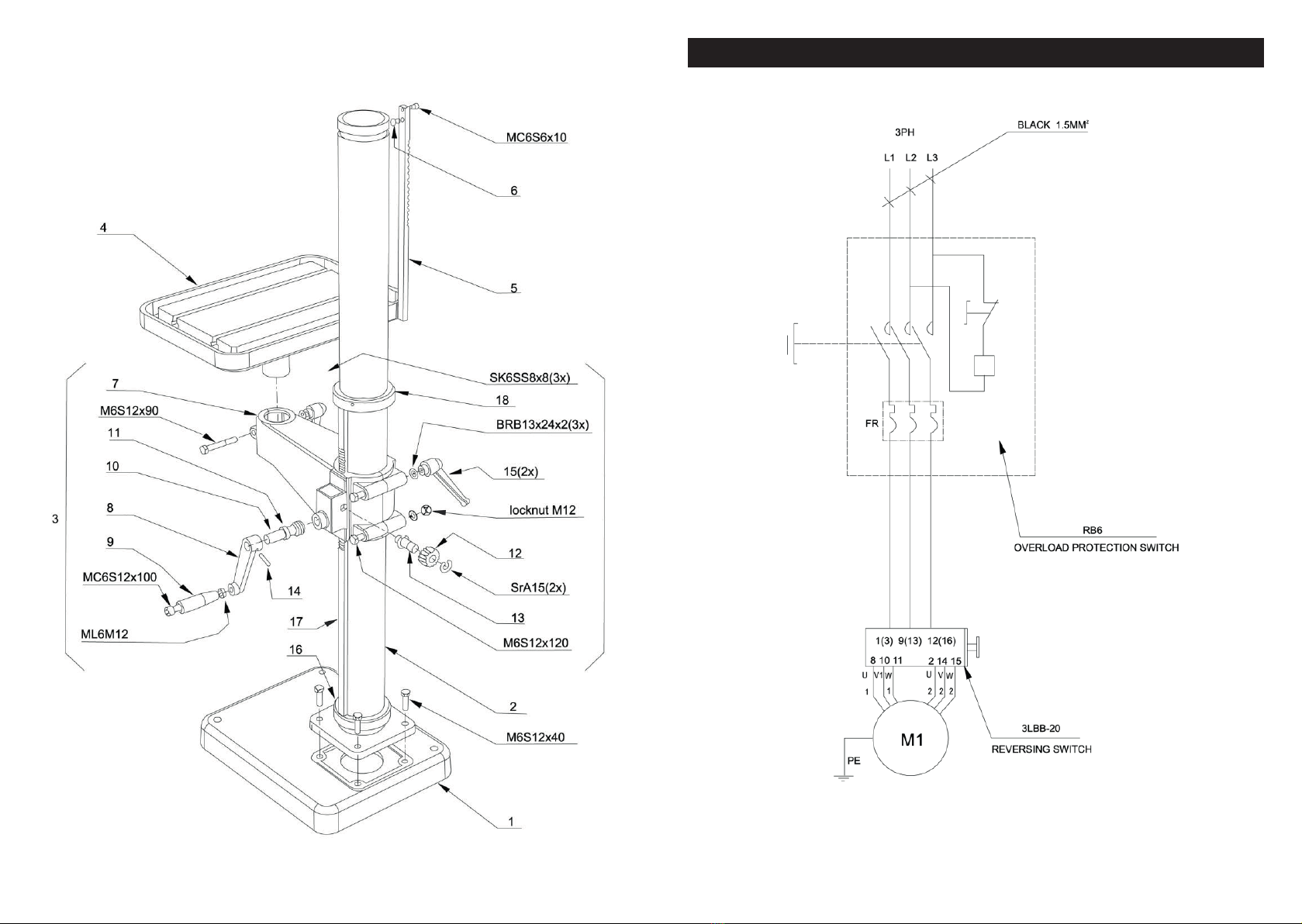
Column
Pos. Cat. no. Description Pos. Cat. no. Description
1. 2W07802 Base plate 10. 2IS1203 Worm gear shaft
2. 4X08300 Column L = 1 500 11. 2D20008 Spacer ring
3. 2X08723 Table arm assembly 12. 2HS1201 Cogged gear
4. 2WS1231 Table 13. 2AS1202 Shaft
5. 2X08445 Cogged rack 14. 3S04444 Stop bolt SK6SS8 × 8
6. 2T07146 Pin 15. 3R00014 Lock handle
7. 2Y08723 Table arm 16. 2N00186 Bottom ring
2X08720-1 Worm gear assembly 17. 2103598 Cogged rack
8. 2RS1182 Handle 18. 2N03668 Top ring
9. 3R01106 Handle
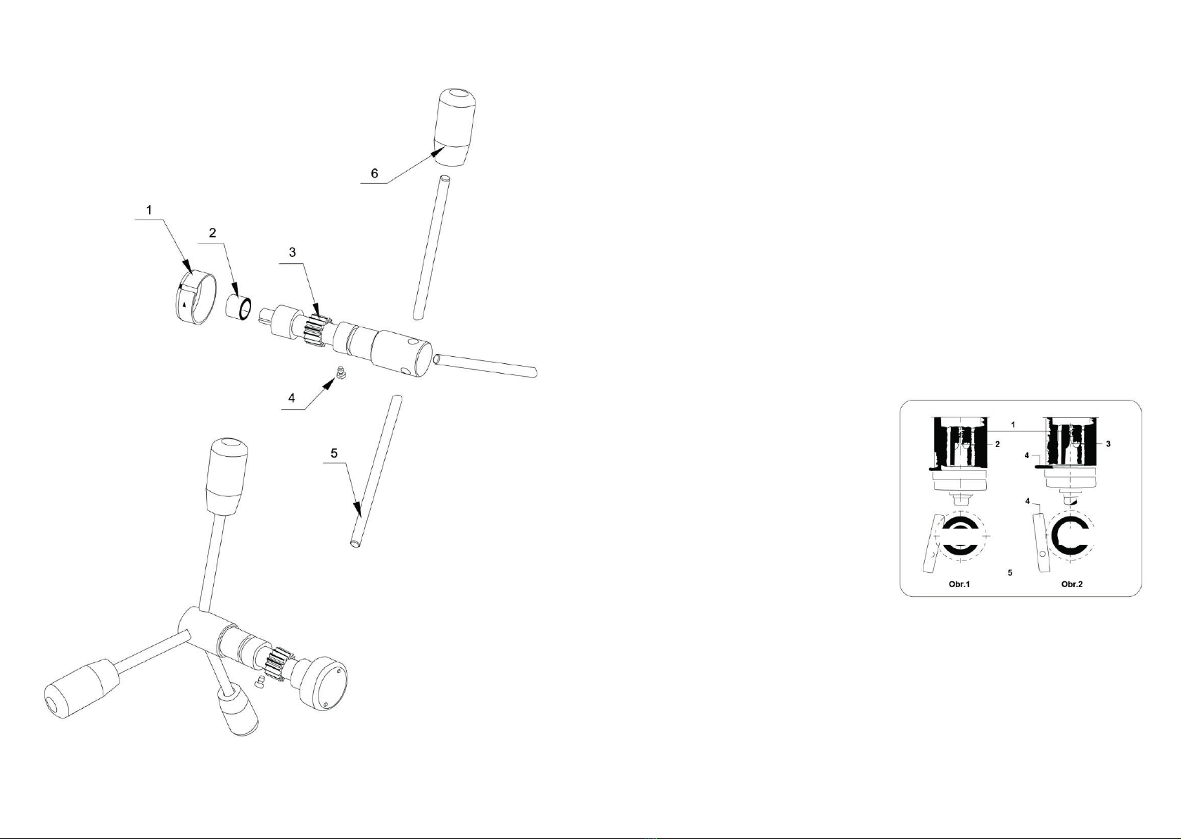
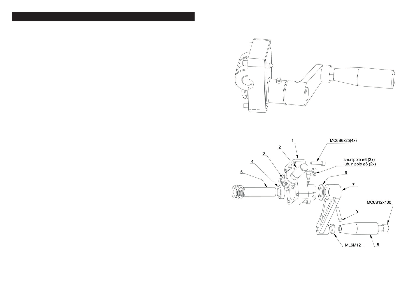
Worm gearbox assembly
Pos. Cat. no. Description Pos. Cat. no. Description
1. 2N08720 Worm gear box 6. 3L00021 Washer
2. 2AS1202 Shaft 7. 2RS1182 Handle
3. 2HS1201 Cogged gear 8. 3R01106 Handle
4. 2D20008 Spacer ring 20 × 8 9. 3S04444 Bolt SK6SS8 × 8
5. 2IS1203 Worm gear shaft
Sliding mechanism shaft
Pos. Cat. no. Description Pos. Cat. no. Description
1. 4T08715 Spring bush 4. 4S04211 Bolt
2. 4C03026 Spring 5. 2E08722 Sliding mechanism lever
3. 2108708 Sliding mechanism shaft 6. 3R02003 Handle
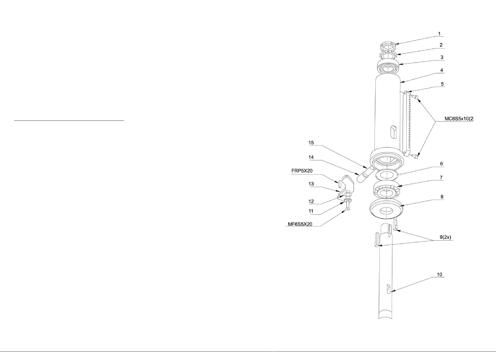
Spindle sleeve
Pos. Cat. no. Description Pos. Cat. no. Description
1. 3M06005 Nut KM5 9. 2T08386 Wedge
2. 4B00155 Lock washer MB 10. 2A08418-1 Spindle
3. 3L11005 Ball bearing 6205 11. 2T08593 Spacer ring
4. 2G08709 Spindle sleeve 12. 3B06003 Washer
5. 2108420 Cogged rack 13. 4T08547 Stopper
6. 4B03769 Washer 14. 3S08622 Bolt 16 × 25
7. 3L51006 Conical bearing 30206 15. 4T08714 Collet
8. 2TS1106 Cylindrical bearing cover
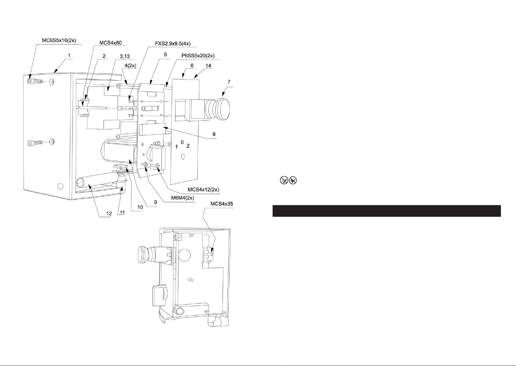
Electrical box
Pos. Cat. no. Description Pos. Cat. no. Description
1. 4U08705 Electric box cover 8. 3T18003 Rubber belt 15 × 8
2. 2L08712 Clamping bar 9. 3E06016 Commutator
3. 3E10604 Motor protection 380/50 10. 3E19088 Nut 1816
4. 2E08713 Electrical box spacer bush 11. 3E19493 Fitting
5. 4L08706 Clamping plate 12. 2T08735 Protective tube
6. 4L08711-3 Electrical box board 13. 3E10614 Undervoltage circuit
breaker
7. 3E16227 Emergency shut-offswitch