High speed and high performance automatic sewing machines
with automatic start and stop of the machine and automatically operated
thread chain or tape cutters for closing filled bags and sacks made of
jute, cotton, paper, plastic or woven polypropylene tapes, bituminized
or foil-laminated materials.
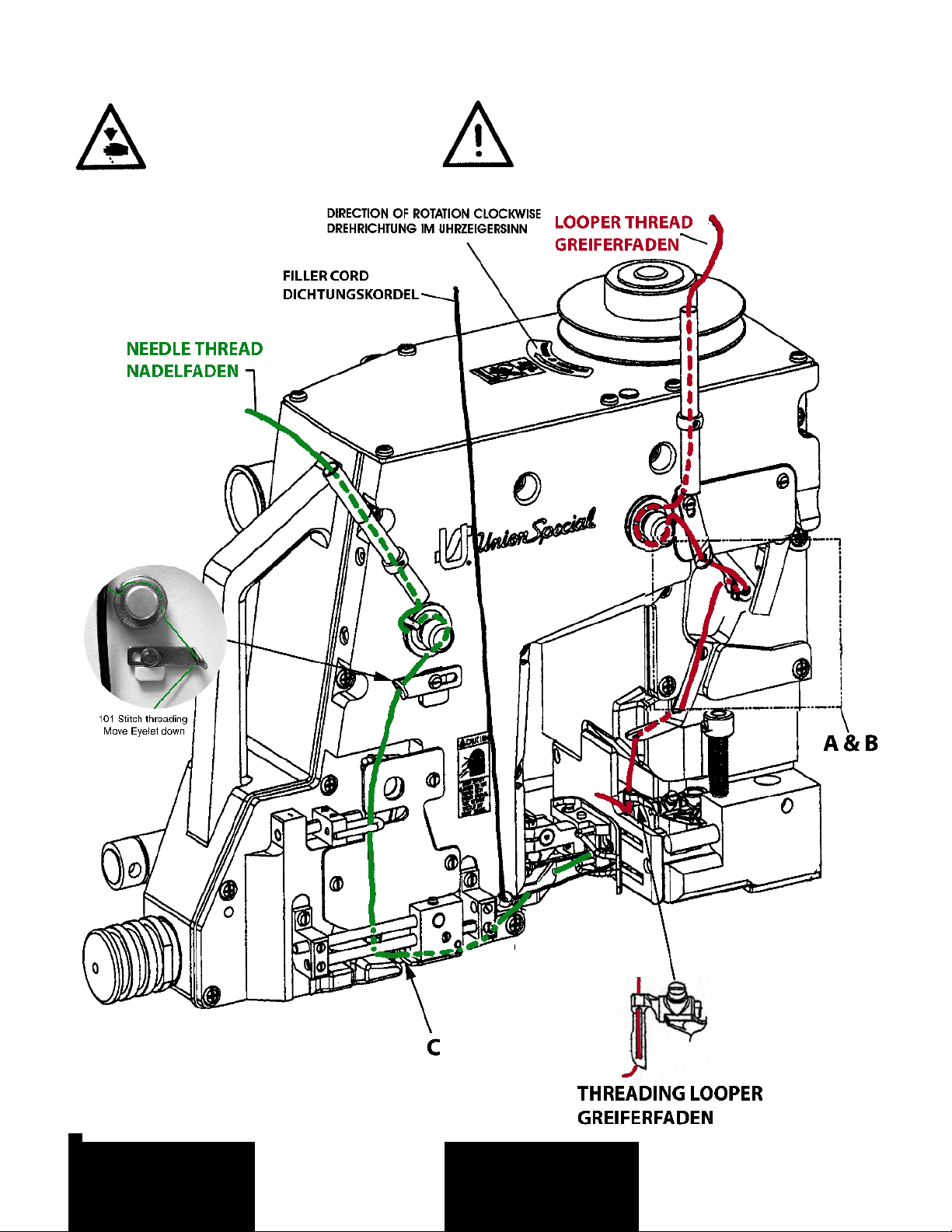
Equipped with guides for application of filler cord for sealing needle
punctures.
The bag being fed into the machine starts the sewing operation by a
feeler controlled, contactless, electronic proximity switch. When the
bag is closed, the machine stops automatically . Thread chain
respectivelly thread chain with binding tape are cut automatically.
One needle, high throw, internal forced lubrication, with automobile type
oil filter, totally enclosed plain feed mechanism, totally enclosed looper
mechanism,independentlydrivenrearneedleguardwithnoreadjustment
required when changing stitch length, and presser foot with
independently spring-loaded chaining section.
BC211P16-1M: Sewing machine for closing filled bags and sacks with
a two thread double locked stitch.
Electro-pneumatically operated jump out knife, actuated by a double
acting cylinder, operating pressure: 44 to 59 PSI (3 to 4 bar).
Degree of protection of solenoid valve: IP65 (IEC 529).
Control Voltage: 24 V DC.
Seam Specification:1.01.01/401 (ISO 4916/4915)
401 SSa-1 (ASTM Standard
No. D6193 – USA)
Stitch Range: 6.5 mm to 12.5 mm (2 to 4 SPI)
Standard Setting: 8 mm (3 SPI)
Capacity Under
Presser Foot: 12.7 mm (1/2 inch)
Sewing Capacity on
Paper Bags: up to 32 plies, depending on
weight of paper
Working Diameters
of the Variable Pitch
Hand Wheel: 90 mm (3.50 inch) to 108 mm
(4.25 inch).
Maximum Speed: up to 2750 stitches/min.,
depending on stitch length, speed
of conveyor, type of operation, and
material to be sewn.
Weight Net: 43 kg
BC211P16-1A: Same as BC211P16-1M, but control voltage 200 - 230
V, 50/60 Hz.
BC211P16-1B: Same as BC211P16-1M, but control voltage 100 - 110
V, 50/60 Hz.
BC211P15-1: Same as BC211P16-1M, but without any electro-
mechanical components and without solenoid valve. With double acting
cylinder.
BC211P15-1NW: Same as BC211P15-1, except with wide sewing
combination and more aggressive feed dog teeth.
BC291P16-1M: Same as BC211P16-1M, but
seam specification 1.01.01/101(ISO 4916 and 4915)
101 SSa-1 (ASTM Standard
No. D6193 - USA
BC211P11-1: Same as BC211P16-1M, but without any electro-
mechanical components and without solenoid valve. With single acting
cylinder.
10008A Blind Looper (extra send and charge item) will produce single
thread chain stitch.
Stitch type: 101 (ISO 4915 / ASTM Standard No. D6193 - USA).
Hochleistungs-Automatik-Nähmaschinen mit automatischem Start und
Stopp der Maschine und automatisch arbeitenden Fadenketten– oder
Bandabschneidern zum Schließen gefüllter Säcke und Beutel aus Jute,
Baumwolle, Papier, Kunststofffolie oder Kunststoffbändchengewebe, sowie
bitumen- oder folienkaschiertem Material.
Ausgestattet mit Führung für Dichtungskordel zum Abdichten der Nadelein-
stiche.
Der in die Maschine einlaufende Sack startet den Nähvorgang über einen
Taster mit kontaktlosem, eletronischem Näherungsschalter. Ist der Sack
verschlossen, stoppt die Maschine automatisch. Die Fadenkette bzw.
Fadenkette mit Einfaßband werden automatisch abgeschnitten.
Eine Nadel, hoher Nadelhub, eingebaute Druckschmierung mit außen
angebrachtem großem Ölfilter, völlig geschlossener Sacktransport-
Mechanismus, völlig geschlossener Greiferantrieb, unabhängig
angetriebener hinterer Nadelanschlag, der bei Stichlängenänderung nicht
nachgestellt werden muß und Drückerfuß mit unabhängig federndem
Kettelteil.
BC211P16-1M: Nähmaschine zum Zunähen gefüllter Säcke und Beutel mit
Zweifaden-Doppelkettenstich.
Elektropneumatische Schere, angesteuert durch doppeltwirkenden
Luftzylinder, erforderlicher Luftdruck: 3 bis 4 bar.
Schutzgrad des Magnetventils: IP65 (IEC 529).
Steuerspannung: 24 V DC.
Nahtbild: 1.01.01/401 (ISO 4916/4915)
401 SSa-1 (ASTM Standard
No. D6193 – USA)
Stichlänge: 6,5 mm bis 12,5 mm
Standard-Einstellung: 8mm
Durchgang unter dem
Drückerfuß: 12,7 mm
Maximale Nähgutdicke
bei Papiersäcken: bis zu 32 Lagen, abhängig vom
Papiergewicht
Wirksamer Durchmesser
des verstellbaren
Handrads: 90 mm bis 108 mm
Maximale Drehzahl: bis 2750 Stiche/Min., abhängig
von Stichlänge, Transportband-
geschwindigkeit, Einsatzzweck
und Material.
Gewicht netto: 43 kg
BC211P16-1A: Wie BC211P16-1M, jedoch mit Steuerspannung 200 - 230
V, 50/60 Hz.
BC211P16-1B: Wie BC211P16-1M, jedoch mit Steuerspannung 100 - 110
V, 50/60 Hz.
BC211P15-1: Wie BC211P16-1M, jedoch ohne elektromechanische
Komponenten und ohne Magnetventil. Mit doppelt wirkenden zylinder.
BC211P15-1NW:WieBC211P15-1,jedochmitbreiteNähenKombinationund
aggressiver Transporteur Zähne.
BC291P16-1M: Wie BC211P16-1M: jedoch
Nahtbild: 1.01.01/101 (ISO 4916 und 4915)
101 SSa-1 (ASTM Standard
No. D6193 - USA)
BC211P11-1: Wie BC211P16-1M, jedoch ohne elektromechanische
Komponenten und ohne Magnetventil. Mit einfach wirkendem Zylinder
10008A Einfachkettenstichgreifer (Extra-Bestellung)
produziert einen Einfaden-Einfachkettenstich.
Nähstichtyp: 101 (ISO 4915 / ASTM Standard No. D6193- USA).
5