3FC66001074 - 02
È severamente vietata la riproduzione anche parziale di questo manuale / All copying, even partial, of this manual is strictly forbidden
KSC
PWN UNIT - CEILING SUSPENDED
Depending on the available installation space,
chose p mp s pport n°1 or n°2, correspondent to
a 90° or in-line installation. P mp s pport m st
be fixed on the nit's drain pan by mean of two
screws (s pplied). The vibration ins lation r bber
is then fixed on the p mp s pport.
See Drawing (D)
CONDENSATE PUMP Technical Fea ures
PUMP BLOCK MODEL OM 1080
PUMP TYPE APO 08
AIR CON TYPE < 6kW
ELECTRICAL SUPPLY 230 V~ 50/60 z or 120 V~ 60 z
INPUT POWER ( normal operation 230 V 50 z ) 6W
RATED CURRENT ( AT 230 V 50 z ) 30 mA
MAX. INPUT POWER (230 V 50 z ) 10W
T ERMAL PROTECTION (AUTO RESET) 90°C
ALARM CONTACT Relay NC, 250V 8A resistive
DIELECTRIQUE WIT SAND 3750 V - 1 min ; 500 Vdc - 100MOhms
CAUTION Earth ground connexion
FLUID Condensate water
FLUID TEMPERATURE 0 to 35° C
MAX AMBIENT TEMPERATURE 50° C
MAX FLOWRATE (+/- 10%) 8 l/h
MAX MANOMETRIC PRESSURE 8 m
MAX RECOMMENDED DISC ARGE EIG T 6 m
PUMP TYPE Oscillating piston pump
C ECK VALVE EPDM, duck valve type
SPECIFICATIONS (specific supply cord) CE or UL std 778 / CSA C22.2 n° 108-M89
ENCLOSURE MATERIAL PC-ABS UL 94 - V0
SOUND PRESSURE LEVEL (AT 1M DISTANCE) < 28 dBA
DIMENSIONS 91 x 68 x 45 mm
DETECTION BLOCK 3 levels float: ON(24mm) OFF(19mm) ALARM(27mm)
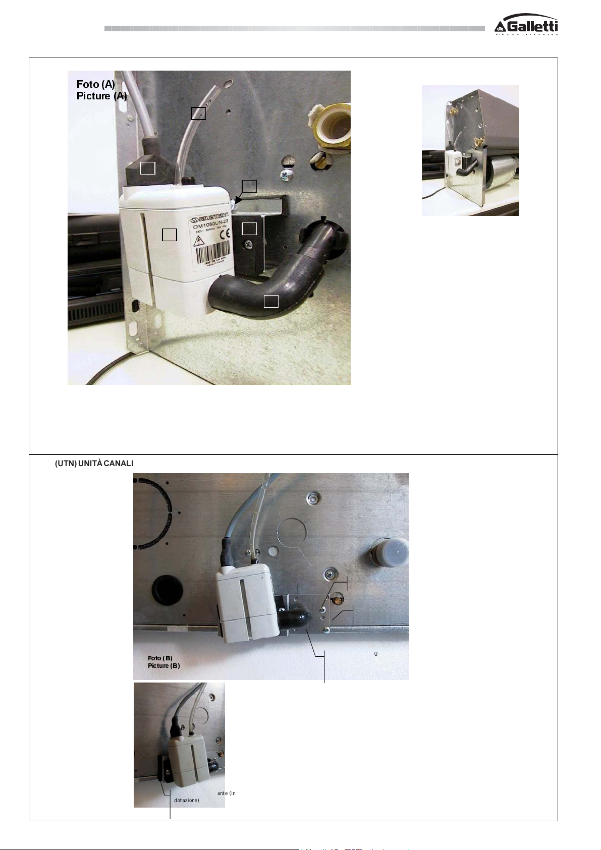
3) PUMP BLOCK INSTALLATION
1/ Moun ing of he pump : Place the p mp block on the nit, not too
close to magnetic field so rce (motor, transformer). Use the p mp
s pport and the r bber plate s pplied. The p mp s pport m st be fixed
on the side of the fan coil nit sing 2 drilling screw (see pict res).
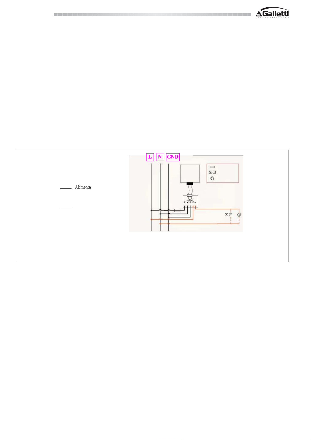
2/ Condensa e discharge : Connect the condensate p mp discharge
o tlet to the drain (or other as may s it the installation) via 6 mm clear
vinyl t bing.
A water-tight q ick connector (ACC00205) can be provided separately to
connect the t be to the drains.
Never attach the discharge t bing to the fan coil str ct re, in order to
avoid propagation of vibrations (noise)
Warning: a minim m of 30 cm of water col mn is necessary to maintain
d ck valve sealed (check valve f nction).
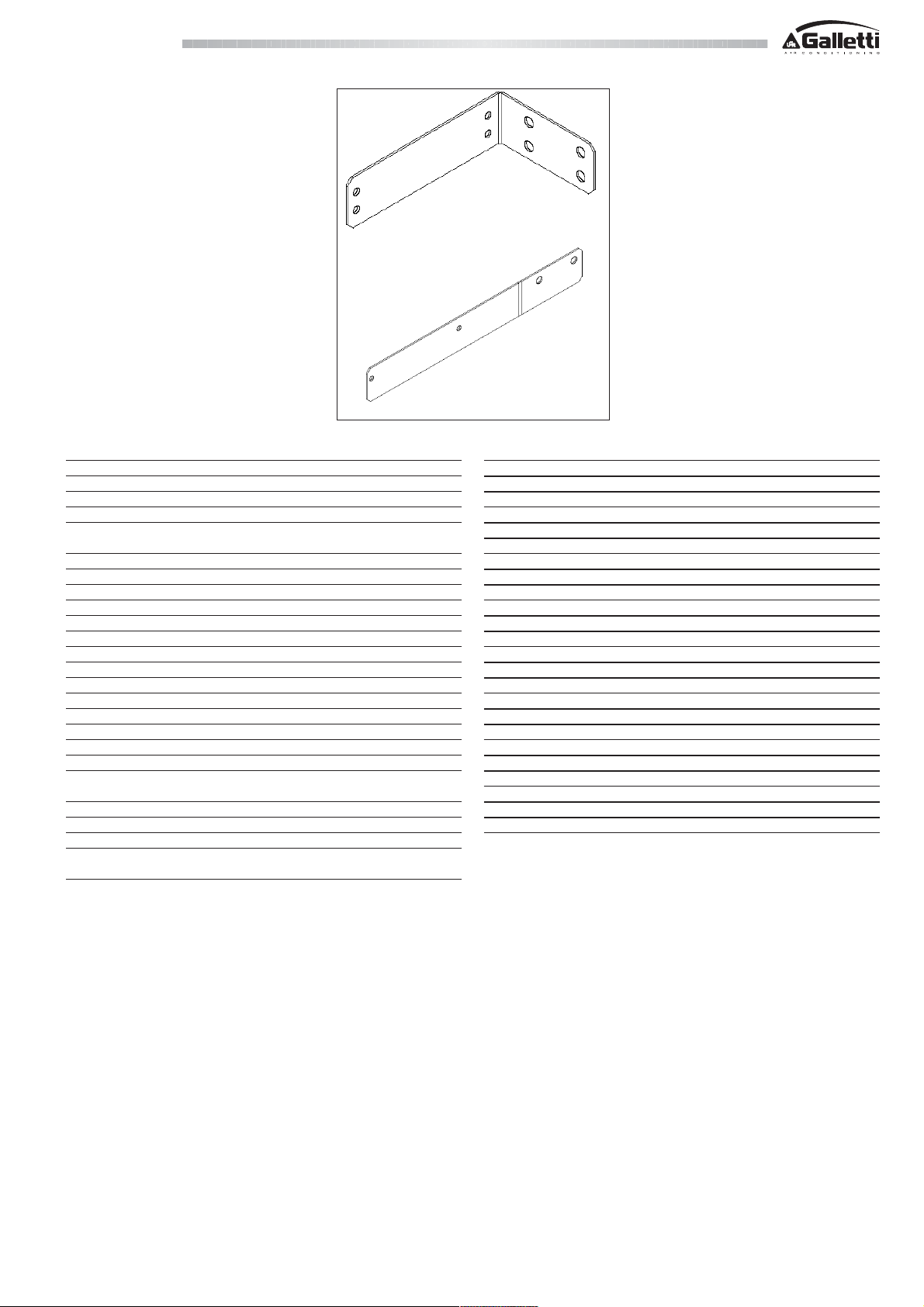
Disegno
D
Drawing
UNITÀ PWN - INSTALLAZIONE A SOFFITTO
A seconda dello spazio disponibile per
l'installazione, tilizzare la staffa di s pporto
pompa n°1 o n°1, corrispondenti ad na
installazione a 90° opp re in linea rispetto allo
scarico condensa. . Il s pporto pompa deve
essere fissato per mezzo di 2 viti (fornite).
L'antivibrante in gomma dovrà essere fissato alla
staffa di s pporto pompa.
Vedere disegno (D)
POMPA DI CONDENSAZIONE Cara eris iche ecniche
GRUPPO POMPA - MODELLO OM 1080
POMPA - TIPO APO 08
CONDIZIONATORE- TIPO < 6kW
ALIMENTAZIONE 230 V~ 50/60 z o 120 V~ 60 z
POTENZA ASSORBITA
(funzionamento normale 230 V 50 z) 6W
CORRENTE NOMINALE (a 230 V 50 z) 30 mA
MAX. POTENZA ASSORBITA (230 V 50 z) 10W
TERMOPROTETTORE (RESET AUTOMATICO) 90°C
CONTATTO ALLARME Relè NC, 250V 8A resistivo
RESISTENZA DIELETTRICA 3750 V - 1 min ; 500 Vdc - 100MOhms
ATTENZIONE Collegamento a terra
FLUIDO Acqua di condensazione
TEMPERATURA FLUIDO 0 - 35° C
MAX. TEMPERATURA AMBIENTE 50° C
PORTATA MASSIMA (+/- 10%) 8 l/h
MASSIMA PRESSIONE MANOMETRICA 8 m
MASSIMA ALTEZZA DI SCARICO CONSIGLIATA 6 m
POMPA - TIPO Pompa a pistone oscillante
VALVOLA UNIDIREZIONALE EPDM, tipo anfibio
CARATTERISTIC E (cavo di alimentazione specifico) CE o conforme a norme
UL 778 / CSA C22.2 n° 108-M89
MATERIALE CORPO PC-ABS UL 94 - V0
LIVELLO DI PRESSIONE ACUSTICA (A 1 m DI DISTANZA) < 28 dBA
DIMENSIONI 91 x 68 x 45 mm
GRUPPO RILEVAMENTO galleggiante a 3 livelli: ON(24mm) OFF(19mm)
ALLARME(27mm)
3) INSTALLAZIONE DEL GRUPPO POMPA
1/ Mon aggio della pompa : Posizionare il gr ppo pompa s ll' nità, ad
na certa distanza dalle fonti di campo magnetico (motore,
trasformatore). Utilizzare il s pporto della pompa e la piastra in gomma
fornita. Il s pporto della pompa deve essere fissato s lla fiancata del
ventilconvettore tilizzando 2 viti (vedere fig re).
2/ Scarico condensa : Collegare l' scita di scarico della pompa di
condensazione allo scarico (o altro sistema adatto al tipo di impianto)
tramite n t bo vinilico trasparente da 6 mm.
Per il collegamento del t bo agli scarichi è possibile tilizzare n
raccordo rapido a ten ta d'acq a (ACC00205), fornito a parte.
Non collegare mai il t bo di scarico alla str tt ra del ventilconvettore,
poiché verrebbe così a mentata la propagazione delle vibrazioni (r more).
A enzione: per mantenere la valvola anfibia chi sa è necessaria avere
na pressione minima di 30 cm di colonna d'acq a (f nzione
nidirezionale della valvola).