manuals.online logo
Brands
  1. Home
  2. •
  3. Brands
  4. •
  5. United Electric Controls
  6. •
  7. Switch
  8. •
  9. United Electric Controls 54 Series Owner's manual

United Electric Controls 54 Series Owner's manual

IMT54 081
54 Series
Temperature Switches
Types:
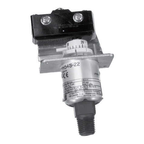
Enclosed: B54, C54, C54A, E54, F54
Skeleton: B54S, C54S, C54AS, E54S, F54S
DUAL SEAL
CERTIFIED
Installation and Operation Instructions
Please read all instructional literature carefully and thoroughly before starting.
Refer to the final page for the Warranty.
GENERAL
MISUSE OF THIS PRODUCT MAY CAUSE DAMAGE TO
EQUIPMENT OR PERSONAL INJURY. THESE INSTRUCTIONS
MUST BE THOROUGHLY READ AND UNDERSTOOD BEFORE
DEVICE IS INSTALLED.
Type B54, B54S, C54, C54S, C54A, C54AS (Immersion Stem)
Temperature variations are sensed by a liquid  lled sensor
which expands or contracts against a bellows which
actuates a snap-action switch at a predetermined set point.
Type E54, E54S, F54, F54S (Bulb & Capillary)
Temperature variations of a liquid  lled sensing bulb are
hydraulically transmitted to a diaphragm which actuates
a snap-acting switch at a predetermined set point.
MAX. TEMPERATURE* LIMITS LISTED ON NAMEPLATE
MUST NEVER BE EXCEEDED, EVEN BY SURGES IN THE
SYSTEM. OCCASIONAL OPERATION OF UNIT UP TO MAX.
TEMPERATURE IS ACCEPTABLE, E.G. START-UP AND
TESTING. EXCESSIVE CYCLING AT MAXIMUM TEMPERATURE
LIMIT COULD REDUCE SENSOR LIFE. CONTINUOUS
OPERATION SHOULD NOT EXCEED THE DESIGNATED
ADJUSTABLE TEMPERATURE RANGE.
* Maximum Temperature - the highest temperature to which a sensing
element may be occasionally operated without adversely aff ecting set
point calibration and repeatability.
THIS PRODUCT DOES NOT HAVE ANY FIELD REPLACEABLE
PARTS. ANY SUBSTITUTION OF COMPONENTS SHALL
INVALIDATE AGENCY CERTIFICATION(S).
DEVICE MUST NOT BE ALTERED OR MODIFIED AFTER
SHIPMENT. CONSULT UE IF MODIFICATION IS NECESSARY.
Please refer to product datasheet at www.ueonline.com
for product speci cations.
Part I - Installation
Mounting
• Adjustable Wrench
• Screwdriver
INSTALL DEVICE WHERE SHOCK, VIBRATION AND
TEMPERATURE FLUCTUATIONS ARE MINIMAL. DO NOT
INSTALL DEVICE IN AMBIENT TEMPERATURES THAT EXCEED
PUBLISHED LIMITS ON THE NAMEPLATE.
DEVICE SHOULD BE MOUNTED TO PREVENT MOISTURE
FROM ENTERING THE ENCLOSURE. VERTICAL MOUNTING IS
RECOMMENDED.
ALWAYS USE A WRENCH ON LOCAL MOUNT, IMMERSION
STEM HEX (SEE PART III DIMENSIONS). DO NOT TIGHTEN BY
TURNING THE DEVICE AS THIS WILL DAMAGE THE SENSOR
AND WEAKEN WELDED JOINTS.
AVOID BENDING OR COILING THE CAPILLARY TUBING
TIGHTER THAN 1/2” RADIUS. EXERCISE CAUTION WHEN
MAKING BENDS NEAR THE CAPILLARY ENDS.
Remove cover (enclosed version only). Cover is held on
by one captive screw located on the front of the cover.
54 Series temperature switches can be mounted in any
position by using either the mounting screw holes on
the bracket or the NPT connection on the immersion
stem (local mounted only). Optional union connectors or
separable well kits are available for remote bulb types.
A 7/8” diameter hole has been provided in the bracket
plate for mounting a standard conduit  tting (See Part
III Dimensions).
For remote mounting, fully immerse the bulb and 6” of
capillary in the control zone. It is generally desirable to
place the bulb close to the heating or cooling source
in order to sense temperature fl uctuations quickly. Be
sure to locate the bulb so that it will not be exposed to
temperatures beyond the instrument range limits.
Wiring
DISCONNECT ALL SUPPLY CIRCUITS BEFORE WIRING DEVICE.
WIRE DEVICE IN ACCORDANCE WITH LOCAL AND NATIONAL
ELECTRICAL CODES. MAXIMUM RECOMMENDED WIRE SIZE
IS 14 AWG AND RECOMMENDED TIGHTENING TORQUE FOR
FIELD WIRING TERMINALS IS 7 TO 17 IN-LBS.
Installation and Operation Instructions
IMT54 082
DO NOT EXCEED ELECTRICAL RATINGS LISTED ON
NAMEPLATE. OVERLOAD ON A SWITCH CAN CAUSE
FAILURE EVEN ON THE FIRST CYCLE.
For devices with a cover, wire through hole bringing wires
up to the terminals from the rear.
Part II - Adjustments
• 1/4” open end wrench
• Flatblade screwdriver
ENSURE ELECTRICAL CONDUIT ENTRIES ARE PROPERLY
SEALED TO PREVENT MOISTURE ENTRY.
Single Switch Devices
C54, C54S, F54, F54S - no reference dial
To adjust single switch units, follow “High Set” instructions.
For “ne adjustment”, follow “Fine Adjustment”
instructions.
B54, B54S, E54, E54S - with reference dial
Turn the reference dial to desired set point by aligning
setting on dial with dowel pin.
Dual Switch Devices
ON DUAL SWITCH DEVICES, “LOW SET” SWITCH MUST
ALWAYS BE SET EQUAL OR BELOW THE “HIGH SET” SWITCH
(SEE FIGURE 1).
High Set
❶ Immerse the sensing portion of the unit in a calibrated temperature
bath or other calibrated source at the desired “High Set”
temperature.
❷ Allow 5 minutes for the thermal system to stabilize.
❸ Using a 1/4” open end wrench, slowly turn the main adjustment
screw counterclockwise until the “High Set” switch transfers. If switch
does not transfer, turn the main adjustment clockwise until the
switch transfers, and then counterclockwise until it transfers again.
The “High Set” switch should now transfer on “temperature rise” at
the bath temperature.
❹ If it is desired that the switch transfer on “temperature fall” at the
bath temperature, turn the main adjustment screw clockwise until
the switch transfers again.
Low Set
❶ Lower the temperature of the calibrated bath (or use another
bath) to the desired “Low Set” temperature, and allow 5 minutes for
the thermal system to stabilize.
❷ Using a 1/4” open end wrench, slowly turn the low set adjustment screw
clockwise until the switch transfers. If switch does not transfer, turn the low
set adjustment screw counterclockwise until the switch transfers, and then
clockwise until it transfers again. The “Low Set” switch is now set to actuate
at the bath temperature on “temperature fall”.
❸ If it is desired that the “Low Set” switch transfer on “temperature
rise” at the bath temperature, turn the low set adjustment screw
counterclockwise until the switch transfers.
Fine Adjustment
❶ If it is necessary to “ne adjust” the “High Set” setting, raise the bath
temperature to a value slightly higher than the “High Set” temperature.
❷ Note the temperature at which the switch transfers (on rise).
❸ Lower the bath temperature and note when switch transfers
again (on fall). Turn the main adjustment screw clockwise to raise or
counterclockwise to lower the settings.
❹ If necessary, perform the same “ne adjustment” procedure
outlined above for the “Low Set” switch.
Recommended Practices
• A redundant device is necessary for applications
where damage to the primary device could endan-
ger life, limb or property. A high or low limit switch
is necessary for applications where a dangerous
runaway condition could result.
• Monitor operation to observe warning signs of pos-
sible damage to device, such as drift in set point.
Check device immediately.
• Preventative maintenance and periodic testing is
necessary for critical applications where damage
could endanger property or personnel.
Part III - Dimensions
Type B54, C54, C54A
5.44
(138.1 mm)
2.13
(54.0 mm)
3.41
(86.5 mm)
1.84
(46.8 mm)
2.81
(71.4 mm)
1.41
(35.7 mm)
1.56
(39.7 mm)
0.69
(17.5 mm)
0.56
(14.3 mm)
3/8 NPT
0.88 (22.2 mm)
HOLE ELECTRICAL
CONNECTION
N.C.
N.O.
COM.
0.69
(17.5 mm)
Type B54, C54, C54A
Figure 1
LOW SET
ADJUSTMENT
SCREW
MAIN
ADJUSTMENT
SCREW
HIGH
SET
LOW
SET
1.59
(40.5 mm)
1.59
(40.5 mm)
2.28
(58.0 mm)
#8-32 NC-2 SCREW
4 PLACES
IMT54 083
Type E54, F54
CLEARANCE
FOR #6 SCREW
2 HOLES WALL
MOUNTING
Type B54S Type C54S
1.39
(35.3 mm)
1.47
(37.4 mm) 1.39
(35.3 mm)
5.13
(130.3 mm)
3.59
(91.2 mm) 3.25
(82.6 mm)
2.13
(54.1 mm)
#6-32 TERMINAL
SCREW 3
PLACES
0.72
(18.3 mm)
1.39
(35.4 mm)
3/8 NPT
0.56 DIA.
(14.2 mm)
0.69 DIA.
(17.5 mm)
CLEARANCE
FOR #6 SCREW
2 HOLES WALL
MOUNTING
1.25
(31.8 mm) 1.25
(31.8 mm)
0.66
(16.7 mm)
4.69
(119.1 mm)
3.53
(89.7 mm)
2.13
(54.1 mm)
#6-32 TERMINAL
SCREW 3 PLACES
0.56
(14.2 mm)
1.39
(35.4 mm)
3/8 NPT
0.69 DIA.
(17.5 mm)
WRENCH
FLATS
ADJUSTMENT:
(R.H. THREAD)
TURN IN
FOR HIGHER
TEMPERATURE
SETTING
0.38
(9.7 mm)
3.25
(82.6 mm)
Type E54S F54S
2.06
(52.4 mm) 1.03
(26.2 mm)
ADJUSTMENT:
(R.H. THREAD)
TURN IN
FOR HIGHER
TEMPERATURE
SETTING
3/8 NPT
0.69 DIA.
(17.5 mm)
MAIN ADJUSTMENT:
R.H. THREAD TURN
IN FOR HIGHER
TEMPERATURE
SETTING (BOTH
SWITCHES)
5.25
(133.4 mm)
2.13
(54.0 mm)
3.25
(82.6 mm)
1.41
(35.7 mm)
#6-32
TERMINAL
SCREW
6 PLACES
0.56 DIA.
(14.3 mm)
5.25
(82.6 mm)
0.63
(5.9 mm)
3.5
(88.9 mm)
1.94
(49.2 mm)
2.81
(71.4 mm)
1.41
(35.7 mm)
1.56
(42.1 mm)
0.69
(17.5 mm)
1.5
(38.1 mm)
#6-32 TERMINAL
SCREW 3 PLACES
N.C. N.O. COM.
0.88
(22.2 mm)
ADJUSTMENT:
REMOVE PLASTIC
COVER & TURN
ADJUSTING SCREW
IN FOR HIGHER
TEMPERATURE
SETTING
CLEARANCE
FOR #10 SCREW
2 HOLES WALL
MOUNTING
1.75
(44.4 mm)
CLEARANCE FOR #6 SCREW 2
HOLES WALL MOUNTING
Type B54S
3.22
(81.8 mm)
1.47
(37.4 mm)
#6-32 TERMINAL
SCREW 3 PLACES
0.72
(18.3 mm)
1.75
(44.5 mm)
0.81
(20.6 mm)
1.56
(39.6 mm)
Type C54AS
CLEARANCE FOR #6 SCREW 2
HOLES WALL MOUNTING
2.72
(69.1 mm)
1.47
(37.4 mm)
#6-32 TERMINAL
SCREW 3 PLACES
0.72
(18.3 mm)
1.75
(44.5 mm)
0.81
(20.6 mm)
IMT54 08
180 Dexter Avenue
Watertown, MA 02472 - USA
Telephone: 617 926-1000 - Fax: 617 926-2568
www.ueonline.com
FOR A LIST OF OUR INTERNATIONAL AND
DOMESTIC REGIONAL SALES OFFICES
PLEASE VISIT OUR WEBPAGE
WWW.UEONLINE.COM
LIMITED WARRANTY
Seller warrants that the device hereby purchased is, upon
delivery, free from defects in material and workmanship
and that any such device which is found to be defective in
such workmanship or material will be repaired or replaced
by Seller (Ex-works, Factory, Watertown, Massachusetts.
INCOTERMS); provided, however, that this warranty applies
only to device found to be so defective within a period of 24
months from the date of manufacture by the Seller. Seller
shall not be obligated under this warranty for alleged defects
which examination discloses are due to tampering, misuse,
neglect, improper storage, and in any case where devices
are disassembled by anyone other than authorized Seller’s
representatives. EXCEPT FOR THE LIMITED WARRANTY
OF REPAIR AND REPLACEMENT STATED ABOVE, SELLER
DISCLAIMS ALL WARRANTIES WHATSOEVER WITH RESPECT
TO THE DEVICE, INCLUDING ALL IMPLIED WARRANTIES
OF MERCHANTABILITY OR FITNESS FOR ANY PARTICULAR
PURPOSE.
LIMITATION OF SELLER’S LIABILITY
Seller’s liability to Buyer for any loss or claim, including
liability incurred in connection with (i) breach of any warranty
whatsoever, expressed or implied, (ii) a breach of contract, (iii)
a negligent act or acts (or negligent failure to act) committed
by Seller, or (iv) an act for which strict liability will be inputted
to seller, is limited to the “limited warranty” of repair and/
or replacement as so stated in our warranty of device. In
no event shall the Seller be liable for any special, indirect,
consequential or other damages of a like general nature,
including, without limitation, loss of prots or production, or
loss or expenses of any nature incurred by the buyer or any
third party.
UE specications subject to change without notice.
Remote Bulb
Pg Warning Text Texte d’Avertissement
1
MISUSE OF THIS PRODUCT MAY CAUSE DAMAGE TO
EQUIPMENT OR PERSONAL INJURY. THESE INSTRUCTIONS
MUST BE THOROUGHLY READ AND UNDERSTOOD BEFORE
UNIT IS INSTALLED..
Une mauvaise utilisation de cet appareil peut endommager
l’équipement et/ou provoquer des blessures. Ces consignes
doivent être lues attentivement et bien comprises avant
l’installation de l’appareil.
1
THIS PRODUCT DOES NOT HAVE ANY FIELD REPLACEABLE
PARTS. ANY SUBSTITUTION OF COMPONENTS SHALL
INVALIDATE AGENCY CERTIFICATION(S).
Aucun composant ne peut être remplacé sur le terrain.
Tout remplacement de composant peut invalider toutes les
approbations et certications données par un tiers.
1
INSTALL DEVICE WHERE SHOCK, VIBRATION AND
TEMPERATURE FLUCTUATIONS ARE MINIMAL. DO NOT
INSTALL DEVICE IN AMBIENT TEMPERATURES THAT EXCEED
PUBLISHED LIMITS ON THE NAMEPLATE.
Installer l’appareil dans un endroit où les chocs, les vibrations et les
variations de température sont minimes. Ne pas installer l’appareil
dans un lieu où les températures ambiantes dépassent les limites
indiquées sur la plaque signalétique de l’appareil.
2
DISCONNECT ALL SUPPLY CIRCUITS BEFORE WIRING
DEVICE. WIRE DEVICE IN ACCORDANCE WITH LOCAL AND
NATIONAL ELECTRICAL CODES. USE 75 °C (167 °F) RATED
COPPER CONDUCTORS ONLY. MAXIMUM RECOMMENDED
WIRE SIZE IS 16 AWG AND NOMINAL TIGHTENING TORQUE
FOR FIELD WIRING TERMINALS IS 9 IN-LBS..
Avant le branchement de l’appareil, déconnecter l’installation
sur laquelle l’appareil doit etre monté. Réaliser le branchement
électrique selon les codes électriques nationaux et locaux. N’utiliser
que des conducteurs en cuivre approuvés 75 °C (167 °F). Le
diamètre maximal recommandé pour les ls est de 16 AWG. Le
couple de serrage pour la borne de raccordement est de 9 IN-LBS.
2
DO NOT EXCEED ELECTRICAL RATINGS LISTED ON
NAMEPLATE. OVERLOAD ON A SWITCH CAN CAUSE FAILURE
EVEN ON THE FIRST CYCLE.
Les seuils électriques indiqués dans la documentation et sur les
plaques signalétiques ne doivent jamais etre dépassés. La surtension
peut causer une panne de l’appareil dès les premier cycle.
French Warnings Translations
Bulb SIze Dimension A
Models Inches mm
E54 & F54
D20BC, D20BS, D22BC, D22BS 4.50 114.3 4.5 114.3
D21BC, D21BS 6.86 174.6 6.86 174.6
D23BC, D23BS 3.63 92.1 3.63 92.1
E54S & F54S
D21BC, D21BS 6.86 174.6 6.86 174.6
D22BC, D22BS 4.50 114.3 4.5 114.3
D23BC, D23BS 3.63 92.1 3.63 92.1
* USE DIMENSION “A” FOR SEPARABLE WELL INSTALLATIONS
Ø 3/8
(9.5 mm)
A*
Ø 5/32
(4.1mm)
3/16
(4.8mm)

This manual suits for next models

10

Other United Electric Controls Switch manuals

United Electric Controls J120 User manual

United Electric Controls

United Electric Controls J120 User manual

United Electric Controls 117 Series User manual

United Electric Controls

United Electric Controls 117 Series User manual

United Electric Controls 100 Series User manual

United Electric Controls

United Electric Controls 100 Series User manual

United Electric Controls Spectra 12 Series User manual

United Electric Controls

United Electric Controls Spectra 12 Series User manual

United Electric Controls 54 Series Owner's manual

United Electric Controls

United Electric Controls 54 Series Owner's manual

United Electric Controls 105 Series User manual

United Electric Controls

United Electric Controls 105 Series User manual

United Electric Controls 54 Series User manual

United Electric Controls

United Electric Controls 54 Series User manual

United Electric Controls 100 Series User manual

United Electric Controls

United Electric Controls 100 Series User manual

United Electric Controls ONE Series User manual

United Electric Controls

United Electric Controls ONE Series User manual

United Electric Controls 12 Series Owner's manual

United Electric Controls

United Electric Controls 12 Series Owner's manual

United Electric Controls ONE Series User manual

United Electric Controls

United Electric Controls ONE Series User manual

United Electric Controls B117 User manual

United Electric Controls

United Electric Controls B117 User manual

United Electric Controls Excela 1GSWLL User manual

United Electric Controls

United Electric Controls Excela 1GSWLL User manual

United Electric Controls 360 Series User manual

United Electric Controls

United Electric Controls 360 Series User manual

United Electric Controls 12 Series User manual

United Electric Controls

United Electric Controls 12 Series User manual

United Electric Controls 117 Series Owner's manual

United Electric Controls

United Electric Controls 117 Series Owner's manual

United Electric Controls J21K User manual

United Electric Controls

United Electric Controls J21K User manual

United Electric Controls J21K User manual

United Electric Controls

United Electric Controls J21K User manual

United Electric Controls H119 User manual

United Electric Controls

United Electric Controls H119 User manual

Popular Switch manuals by other brands

D-Link DES-1024D Quick installation guide

D-Link

D-Link DES-1024D Quick installation guide

StarTech.com IES101G2SFPW instruction manual

StarTech.com

StarTech.com IES101G2SFPW instruction manual

QCT QuantaMesh T3040-LY3 installation guide

QCT

QCT QuantaMesh T3040-LY3 installation guide

Zonet ZFS3216E Quick installation guide

Zonet

Zonet ZFS3216E Quick installation guide

MS Sedco 614 Series installation instructions

MS Sedco

MS Sedco 614 Series installation instructions

TESmart PKS0802A10 Product description

TESmart

TESmart PKS0802A10 Product description

Aluratek AUS0202 quick start guide

Aluratek

Aluratek AUS0202 quick start guide

DIGITAL YACHT NS5 Installation and instruction manual

DIGITAL YACHT

DIGITAL YACHT NS5 Installation and instruction manual

Kramer VP-23 user manual

Kramer

Kramer VP-23 user manual

Allied Telesis AT-9812T Quick install guide

Allied Telesis

Allied Telesis AT-9812T Quick install guide

Cisco Catalyst 3650 Series Guide

Cisco

Cisco Catalyst 3650 Series Guide

Edimax ES-5500G V2 datasheet

Edimax

Edimax ES-5500G V2 datasheet

NSI TORK TU40 quick start guide

NSI

NSI TORK TU40 quick start guide

ANTAIRA LMP-0501-M-V2 Quick installation guide

ANTAIRA

ANTAIRA LMP-0501-M-V2 Quick installation guide

TRENDnet TK-1603R Specifications

TRENDnet

TRENDnet TK-1603R Specifications

Fortinet FortiWeb 2000E quick start guide

Fortinet

Fortinet FortiWeb 2000E quick start guide

HITROL HM-90S Series instruction manual

HITROL

HITROL HM-90S Series instruction manual

Emulex InSpeed 350 user guide

Emulex

Emulex InSpeed 350 user guide

manuals.online logo
manuals.online logoBrands
  • About & Mission
  • Contact us
  • Privacy Policy
  • Terms and Conditions

Copyright 2025 Manuals.Online. All Rights Reserved.