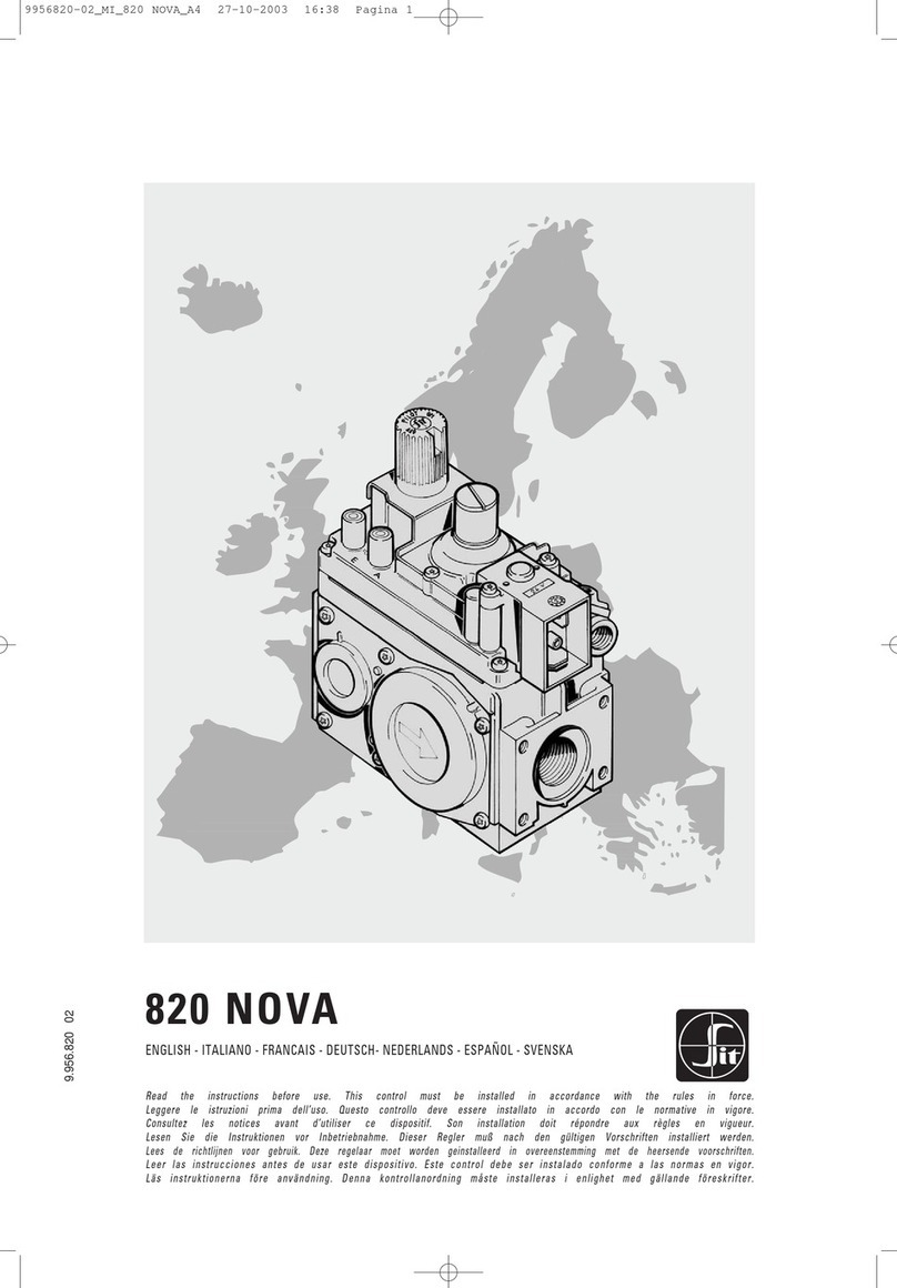
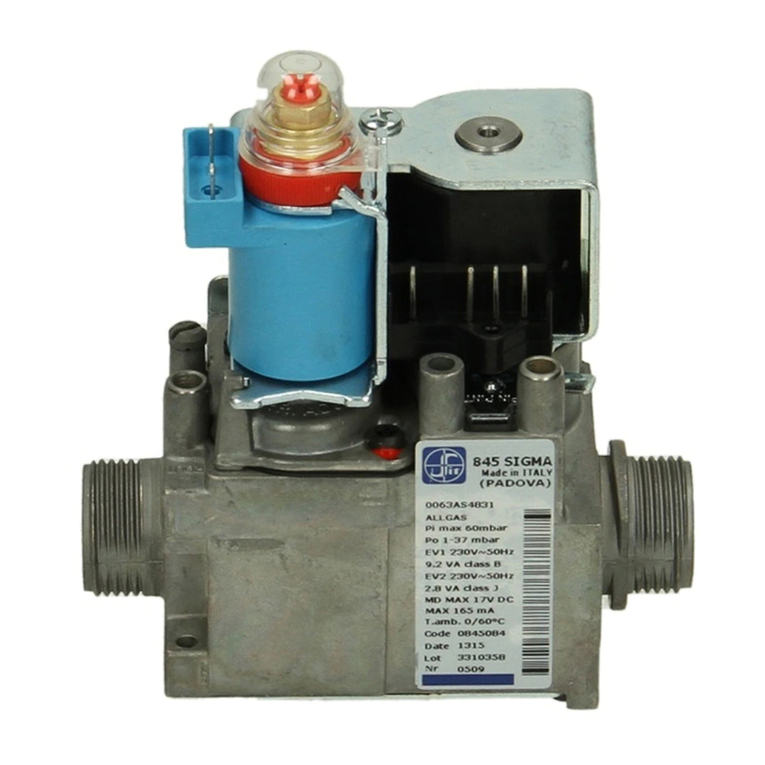
Sit 840 SIGMA User manual

8 4 0 S I G M A
ENGLISH - ITALIANO
Read the ins truc tion s before use. T his co ntro l must be insta lled i n acco rdance with t he rul es in fo rce
Leggere le istruzioni prim a dell ’uso . Ques to con trol lo dev e essere installato in ac cord o con le n orma tive i n vigo re
9.957.840 01


English -
GB 14
4
Italiano
IT 2515

4
Multifunctional gas control with double safety solenoid and servo-assisted gas outlet pressure regulator. The control is
designed for use in appliances with automatic ignition and flame detection systems, with direct burner ignition or
intermittent pilot. All the adjustments can be made from the top face and it is suitable for all three gas families.
DESCRIPTION
1
On-off solenoid valve EV1
2
On-off solenoid valve EV2
3
Inlet pressure test point
4
Outlet pressure test point
5
Connection for pressure regulator/
combustion chamber compensation
6
Pressure regulator
7
Pilot outlet
8
Main gas outlet
9
Side Outlet
WORKING DIAGRAM
PR EV2
FL EV1
FL
MAIN BURNER
PILOT BURNER
87
9
840
840
2
1
5
46
3
MAIN FEATURES
ON/OFF solenoid valves: EV1 Class B (on request class A)
EV2 Class J (on request class C)
Servo pressure regulator (PR) class B
Inlet filter
Outlet filter (optional)
Pilot outlet (optional) with filter
Side outlet (optional)
Connection for pressure regulator/combustion chamber compensation
Inlet and outlet pressure test points with “captured” screws
Two mounting holes
Slow opening ignition device (optional)
USE AND INSTALLATION INSTRUCTIONS

5
ELECTRICAL DATA
TECHNICAL DATA
The technical data specified below refers to the European standard, EN 126 “Multifunctional controls for gas-burning appliances”
Group 2
Automatic valves (EV) EV1 class A or B / EV2 class C or J
Pressure regulator (PR) Class B
Outlet pressure setting range 2-50 mbar
Gas families 1st, 2nd, 3rd
Ambient temperature 0°C...60°C (-20°C...60°C on request)
Maximum inlet pressure 60 mbar
Opening time of automatic valves <2 s
Closing time of automatic valves <1 s
Assembly position any position
Inlet/outlet gas connection Male G3/4 B ISO 228
Connections with flanges M4 (4) flanges minimum full
thread 6 mm
Union joint (accessory 0.982.001)
Female connection Rp 1/2 ISO 7 (105 mm version)
Side oultet M5 (3) flanges minimum full thread 7 mm
Pilot M10 X1 for 4 mm, 6 mm or 1/4” tubing
Pressure test point ∅ 9 mm
Pressure compensation ∅ 7 mm
AUTOMATIC SHUT-OFF VALVES EV1 EV2 EV1 EV2
Nominal Supply Voltage
(AC)
Current nominal voltage
(mA)
Power at nominal voltage
(
W
)
230 V 50 Hz 40 12 4.3 2.0
24 V 50 Hz 390 100 4.6 2.0
Protection degree:
IP 40 with SIT NAC 504 connector. IP 44 with SIT NAC 504 connector and gasket
IP 40 or IP 44 with connectors 960.4 serie
ENGLISH

6
GAS FLOW
510 15 20
3
4
5
25
6
7
8
6 8 10 12 14 16
2
4
8
6
10
12
0
Regulated flow Q
as a function to outlet pressure Pu,
according to EN 126
0
2
2
4
46810
6
8
10
1
Solenoid valves class B+J
Q [m3/h d=0.55]
∆P [mbar]
Flowrate at
∆
P = 5 mbar
1
st
d=0.41
2
nd
d=0.55
3
rd
d=1.55
Gas Family
6 m
3
/h
7 m
3
/h
3.6 m
3
/h
Class B+J
Flow Q
as a function of pressure,
drop
∆
P
Third Family Group B/P and Group P
Inlet pressure range (mbar)
Nominal Max. Min. Relative
Density
B/P 29 35 25 2.075
P 37 45 25 1.555
Second Family Group H, E and L
Inlet pressure range (mbar)
Nominal Max. Min. Relative
Density
H-E 20 25 17 0.555
L 25 30 20 0.612
Minimum flowrate 0.3 m3/h d=0.55
Pu [mbar]
Pu [mbar]
Q [m
3
/h]
Solenoid valves class B+J
Q [m
3
/h]
Solenoid valves class B+J
L
H-E
P
B/P
ENGLISH

7
• Do not tamper with sealed parts
• Do not slacken assembly screws
• Do not remove labels
• Avoid blows (knocks, falls etc.)
• Only remove dust caps when installing
• Do not exceed recommended torques
• Ensure that the gas flows in the direction
shown by the arrow on the valve body
• Do not subject the valve to bending in excess of 35 Nm and
torque in excess of 25 Nm
•Use only the specified spanner grips when making the
connections
•Do not immerse in water or subject the valve (MFC) to
temperatures exceeding 80°C
• Turn off gas supply before starting installation
INSTALLATION
SIT 840 SIGMA complied with current safety standards. Nevertheless, its installation on appliances must be verified in
accordance with the specific standards for each installation.
In particular, it is necessary to ensure that requirements relating to the class of flame failure device, automatic shut-off
valve and pressure regulator are met.
All the installation, setting and adjustement operations must be carried out exclusively by qualified personnel on the
basis of the specific characteristics of the appliance.
MECHANICAL CONNECTIONS
General recommendations:
SLOW OPENING LEVEL ADJUSTMENT
The adjustment is carried out by rotating the adjustment screw. This can rotate up to 270° and every position
corresponds to a specific ignition level. (This is also affected by the outlet pressure level).
The 0° position is obtained by rotating anticlockwise the screw up to the stop position, this then corresponds with the
minimum ignition level. The 270°C position is obtained by rotating clockwise the adjustment screw up to the stop
position and this then corresponds with the maximum level.
The adjustment procedure:
- Ensure that the flame control is the correct version.
- Using a screwdriver, turn the adjustment screw up to the stop position (0°)
- Rotate the adjustment screw anticlockwise to the specific angle required.
- Power the control to activate the ignition procedure
- Verify the ignition conditions
- Disconnect the supply
-Rotate, if necessary the adjustment screw and repeat the process to obtain the optimal situation for the ignition of
the boiler.
WARNING:
If the gas family could be changed it is necessary to reset the slow opening adjustment.
0
0 1 2 3 4 5 6 7 8 9 10
t (sec.)
2
4
6
8
10
12
14
16
Pout (mbar)
270°
180°
0°
ENGLISH

8
Main gas connection
G3/4 version (external thread)
-
Connection with gasket (A)
Use gas pipes with a suitable flat annular surface to allow the use of a sealing gasket.
The locking ring thread shall comply with ISO 228.
Ensure the gasket is suitable for the use.
Apply the proper torque to the locking ring, according to the washer characteristics, in order to ensure the seal.
WARNING:
do not over-tighten the locking ring.
-
Connection with union joint (B)
Use SIT joint 0.982.001.
Ensure the locking ring is properly engaged.
Recommended torque range 40-60 Nm.
Do not overtorque.
connection with union joint
SIT 0.982.001
locking ring
pipe
pipe
connection with gasket
locking ring
gasket
A
B
ENGLISH

9
Flange connections (flanges shall be according ISO 7005)
First screw the pipes into the flanges and then the flanges to the multifunctional control.
Recommended torque for flange retaining screws: 3 Nm.
Caution: check the”0” ring is properly placed in the groove of the flange.
Rp 1/2 connection
Prevent foreign matter from getting into the valve during installation. In particular, check the cleanliness of the
inlet and outlet pipes.
The connection must be made using gas pipes with Rp 1/2 ISO 7 thread. Torque: 25 Nm.
Connection to the pilot burner (versions with pilot burner outlet)
4 mm, 6 mm or 1/4'' pipes can be used. Use appropriately sized nut and olive. Tighten to 7 Nm torque
.
WARNING:
if you don’t use a pilot outlet provided device, you must seal it using optional code no. 0.972.041
Torque: 7 Nm.
ELECTRICAL CONNECTIONS
General precautions
All electrical connections must be made in accordance with current electrical standards. Check that the voltage and
frequency of the coils, given on the valve, are correct. Disconnect the power supply before starting installation.
Check that all connections, in particular the earth, are made properly.
To make this effective you have to use fast-on contact on the body, or a female contact of the connector with correct
characteristic (see EN 60730).
When you use connector, ensure that the fastening screws are never slack.
Automatic valves are powered with a male contact 3003 molex compatible, suitable for female Molex series 3001.
Electrical modulator is powered with a male fast-on connector 2.8 x 0.8 mm.
The 24 Vac versions must be powered by means of an insulating transformer (with very low safety voltage in
accordance with EN 60742). To connect, use AMP 1.1 x 1.1.
Make the connections as specified in the technical instructions for the flame failure device used and/or in the specific
standards for the appliance. The electrical safety cut-off devices (for example, the flame failure device, thermostat
etc.) must cut off the power supply to both solenoid valves simultaneously.
WIRING DIAGRAM
Pin Po
Ve
P.R.A D J.
12 3 4
EV1
EV2
ENGLISH

10
SETTINGS AND ADJUSTMENTS
All adjustments must be made on the basis of the specific characteristics of the appliance. Check inlet and outlet
pressure using the pressure test points provided. After testing, carefully seal test points with the provided screws.
Recommended torque: 1.0 Nm.
Adjusting the outlet pressure
All the adjustments must be carried out in the following order:
Check the inlet PIN and outlet PINT pressure using the pressure test points provided.
Remove the protective plug C using a 4 mm Allen wrench.
Screw in the screw D by using a screw driver with 5.5 x 0.8 blade, to increase the pressure and screw it out to
decrease it.
After setting put back the protective plug.
Gas family change
Check that the appliance is suitable for operation with the gas family in question. Adjust the minimum and maximum
outlet pressures in accordance with the values given in the appliance instruction booklet.
Changing gas group within the same family
Check that the appliance is suitable for operation with the gas group in question. Check in the appliance instruction
booklet if any operations are necessary when changing the gas group. If so, adjust the minimum and maximum gas
outlet pressures in accordance with the appliance manufacturer's instructions and as stated previously.
IMPORTANT:
at the end of all setting and adjustment operations, check electrical insulation, gas seals and the
efficiency of the appliance. In particular, it is necessary to ensure that the flame does not go out and that light back
does not occur at the minimum and maximum gas outlet pressures. After carrying out all adjustments, fit the provided
seals and/or block the setting screws with paint, taking care not to obstruct the breather orifice of the pressure
regulator.
ACCESSORIES
Union joint for main gas connections 0.982.001
Electric supply connector with 3 wires power 0.960.401
Electric supply connector with 4 wires power 0.960.400
D
C

11
Gas connection: G3/4 ISO 228
ENGLISH

12
Gas connection: Flanges
Molex Connector
Side Outlet
* Mounting Holes
80 mm version 105 mm version
Optional Rp 1/2 ISO 7
inlet and outlet connection
ENGLISH

13
SLOW OPENING VERSION - Gas connection: G3/4 ISO 228
11.55 28.95
33
80 15
12.15
18
32
1
55.5
113
75.5
54.5
11.5
27.5
26
12.6
9.611.5
18
15.5
5
21
55.8
24
21
13
Molex Connector
M5 N°3 HOLES
SIDE OUTLET
*Mounting Holes
*
13
12.35
26
32.5 22
ø 32
ø 29
ø 26
G 3/4 - ISO 228/1
112.65
41 - 8.3
M4 N°2 HOLES
1616
2.4
M10x1 6H
28
61
ENGLISH

14
SLOW OPENING VERSION - Gas connection: Flanges
80
21 24 21
112.65
41-8.3
24
16 16
M4 N°4 HOLES
11.55 28.95
26
24
28 33
61
24
2232.5
M4 N°4 HOLES
M10x1 6H
*
75.5
54.5
11.5
27.5
26
18
15.5
5
12.6
9.6
11.5
24 55.8
2.4
Molex Connector
M5 N°3 HOLES SIDE OUTLET
*Mounting Holes
80 mm version 105 mm version
Optional Rp 1/2 ISO 7
inlet and outlet connection
112.65
**Rp 1/2" ISO 7
75.5
54.5
11.5
27.5
26
18
15.5
5
80 12.15
105
12.5
Molex Connector
ENGLISH

15
Controllo multifunzionale dotato di due elettrovalvole di sicurezza e operatore modulante per la regolazione
automatica della pressione in uscita. Il controllo è destinato per uso in applicazioni con sistemi ad accensione
automatica, con accensione diretta del bruciatore o pilota intermittente. Tutte le regolazioni sono accessibili sulla
parte superiore ed è adatto all’uso con tutte le tre famiglie di gas.
DESCRIZIONE
1
Elettrovalvola EV1
2
Elettrovalvola EV2
3
Presa di pressione in ingresso
4
Presa di pressione in uscita
5
Collegamento per il regolatore di pressione/
Compensazione camera di combustione
6
Regolatore di pressione
7
Uscita pilota
8
Uscita gas principale
9
Uscita laterale
SCHEMA DI FUNZIONAMENTO
RP EV2
FL EV1
FL
BRUCIATORE
PRINCIPALE
BRUCIATORE
PILOTA
840
2
1
5
46
3
CARATTERISTICHE PRINCIPALI
Elettrovalvole EV1 Classe B (su richiesta Classe A)
EV2 Classe J (su richiesta Classe C)
Regolatore di pressione tipo servo classe B
Filtro in ingresso
Filtro in uscita (opzionale)
Uscita pilota (opzionale) con filtro
Uscita laterale (opzionale)
Collegamento per il regolatore di pressione/Compensazione camera di combustione
Prese di pressione in entrata e uscita con viti non estraibili
Due fori di fissaggio
Dispositivo di lenta accensione (opzionale)
87
9
840
ISTRUZIONI D’USO E DI INSTALLAZIONE

16
DATI ELETTRICI
DATI TECNICI
I dati tecnici sottoindicati si riferiscono alla normativa standard Europea EN 126 “Controlli Multifunzionali per apparecchi a gas”.
Resistenza alla flessione e alla torsione Gruppo 2
Elettrovalvole (EV) EV1 classe A o B / EV2 classe C o J
Regolatore di Pressione (RP) Classe B
Campo di regolazione pressione in uscita 2-50 mbar
Famiglie di gas di funzionamento 1a, 2a, 3a
Temperatura ambiente d’utilizzo 0°C ...60°C (-20°C ...60°C su richiesta)
Pressione massima di entrata 60 mbar
Tempo di apertura elettrovalvola di sicurezza <2 s
Tempo di chiusura elettrovalvola di sicurezza <1 s
Posizione di montaggio qualsiasi
Connessioni entrata/uscita gas Maschio G3/4 B ISO 228
Connessioni con flange M4 (4). Profondità minima
filettatura 6 mm
Giunto di unione (accessorio 0.982.001)
Connessione Femmina Rp 1/2 ISO 7 (versione 105 mm)
Uscita laterale M5 (3) flange profondità minima filettatura 7 mm
Pilota M10 x 1 con utilizzo tubi da 4 mm, 6 mm, o 1/4”
Prese di pressione ∅9 mm
Collegamento camera di combustione ∅7 mm
VALVOLE AUTOMATICHE EV1 EV2 EV1 EV2
Tensione Nominale
(AC)
Corrente a regime
(mA)
Potenza
(
W
)
230 V 50 Hz 40 12 4.3 2.0
24 V 50 Hz 390 100 4.6 2.0
Grado di protezione:
IP 40 con connettore SIT NAC 504. IP 44 con NAC 504 e guarnizione
IP 40 e IP 44 con connettori serie 0.960.4
ITALIANO

17
PORTATA
510 15 20
3
4
5
25
6
7
8
6 8 10 12 14 16
2
4
8
6
10
12
0
Portate regolate Q in funzione
della pressione di uscita Pu,
rilevate secondo EN 126
0
2
2
4
46810
6
8
10
1
Elettovalvole classe B+J
Q [m3/h d=0.55]
∆P [mbar]
Portata libera
∆
p = 5mbar
1
a
d=0.41
2
a
d=0.55
3
a
d=1.55
Famiglia di gas
6 m
3
/h
7 m
3
/h
3.6 m
3
/h
Classe B+J
Portata Q,
in funzione della perdita di
carico
∆
P
Terza Famiglia Gruppo B/P e Gruppo P
Campo di pressione in ingresso (mbar)
Nominale Massima Minima Densità
B/P 29 35 25 2.075
P 37 45 25 1.555
Seconda Famiglia Gruppo H, E e Gruppo L
Campo della pressione in ingresso (mbar)
Nominale Massima Minima Densità
H-E 20 25 17 0.555
L 25 30 20 0.612
Portata minima 0.3 m3/h d=0.55
Pu [mbar]
Pu [mbar]
Q [m
3
/h]
Elettrovalvole classe B+J
Q [m
3
/h]
Elettrovalvole classe B+J
L
H-E
P
B/P
ITALIANO

18
REGOLAZIONE DEL LIVELLO DI LENTA ACCENSIONE
La regolazione viene effettuata ruotando la vite di regolazione la quale può ruotare di 270° ed a ciascuna posizione
corrisponde un determinato livello di accensione (e quindi un diverso valore della pressione in uscita).
La posizione a 0° si ottiene ruotando tale vite in senso antiorario fino a battuta, ad essa corrisponde il minimo livello di
accensione, la posizione a 270° è quella ottenuta ruotando la vite di regolazione in senso orario fino a battuta e
corrisponde al livello massimo .
Per effettuare la regolazione è necessario:
- assicurarsi che il controllo di fiamma non sia alimentato
- servendosi di un cacciavite portare la vite di regolazione fino a battuta (posizione a 0°)
- ruotare la vite di regolazione in senso orario di un certo angolo
- alimentare il controllo di fiamma per iniziare la procedura di accensione
- verificare le condizioni di accensione
- togliere l’alimentazione
- ruotare eventualmente la vite di regolazione in senso orario od antiorario e ripetere il processo fino ad ottenere una
condizione ottimale relativamente alla potenza ed alla rumorosità della caldaia.
ATTENZIONE:
Qualora il gas di utilizzo dovesse cambiare da un gruppo ad un altro si renderà necessaria una
nuova regolazione.
INSTALLAZIONE
SIT 840 SIGMA è conforme alle norme di sicurezza vigenti. L’installazione sugli apparecchi di utilizzazione va
comunque verificata a fronte delle norme specifiche relative a ciascuna installazione.
In particolare deve essere verificato che siano soddisfatti i requisiti relativi al dispositivo di rilevazione fiamma, della
valvola automatica di intercettazione e del regolatore di pressione.
Tutte le operazioni relative all’installazione, taratura e regolazione devono essere eseguite esclusivamente da
personale qualificato sulla base delle caratteristiche specifiche dell’apparecchio di utilizzazione.
CONNESSIONI MECCANICHE
Avvertenze generali:
• Non manomettere gli organi sigillati
• Non svitare le viti di assiemaggio
• Non rimuovere le marcature
•Evitare alla valvola qualsiasi shock (urti, cadute, etc.)
•Togliere i tappi parapolvere solo all’atto
dell’installazione
•Non superare le coppie di serraggio consigliate
• Assicurarsi che il flusso del gas sia conforme alla
direzione indicata dalla freccia sul corpo della valvola
• Non assoggettare la valvola a sforzi di flessione
superiore a 35 Nm ed a sforzi di torsione superiori a
25 Nm
• Per effettuare i collegamenti bloccare la valvola usando
unicamente la presa di chiave prevista
• Non immergere in acqua o non assoggettare la valvola
a temperature eccedenti 80°C
• Chiudere l’erogazione del gas prima di iniziare
l’installazione
0
0 1 2 3 4 5 6 7 8 9 10
t (sec.)
2
4
6
8
10
12
14
16
Pout (mbar)
270°
180°
0°
ITALIANO

19
Collegamento gas principale
Versione G3/4 (filetto maschio)
-
Collegamento con guarnizione (A)
Usare tubi di gas aventi all’estremità una superficie sufficiente per l’uso di guarnizioni di tenuta.
La filettatura del dado di bloccaggio deve essere conforme ISO 228.
Assicurarsi che la guarnizione sia idonea all’uso.
Applicare la corretta coppia di serraggio, in accordo con le caratteristiche della guarnizione, per garantire
la tenuta.
ATTENZIONE:
non eccedere con la coppia di serraggio per evitare di danneggiare la guarnizione.
-Collegamento con tubo sagomato a tenuta metallica (B)
Usare giunto SIT 0.982.001.
Assicurarsi che il dado sia inserito correttamente.
Coppie di serraggio raccomandate: 40-60 Nm.
Non superare la coppia di serraggio raccomandata.
collegamento con tubo sagomato
a tenuta metallica SIT 0.982.001
dado di bloccaggio
tubo
tubo
collegamento con
guarnizione
dado di bloccaggio
guarnizione
A
B
ITALIANO

20
Collegamenti con flangia (le flange devono essere conformi alla norma ISO 7005)
Prima di tutto avvitare i tubi alle flange e quindi le flange alla valvola.
Coppia di serraggio consigliata per le viti di fissaggio flange: 3 Nm.
Precauzione: controllare che la guarnizione sia posizionata correttamente nell’apposita sede.
Collegamenti con Rp 1/2
Evitare che durante le operazioni di montaggio entrino nella valvola sostanze estranee.
In particolare verificare la pulizia dei tubi in ingresso ed in uscita.
Il collegamento deve essere effettuato utilizzando tubi gas con filettatura Rp 1/2 ISO 7. Coppia serraggio: 25 Nm
Collegamento al bruciatore pilota (versione senza uscita bruciatore pilota)
Possono essere utilizzati tubi di diametro 4 mm, 6 mm, o 1/4’’. Usare raccordo e bicono di adatte dimensioni.
Serrare il raccordo con coppia di 7 Nm.
ATTENZIONE:
se non si usa il dispositivo di uscita pilota previsto, si deve chiuderlo con l’apposito accessorio
codice 0.972.041.
Coppia serraggio: 7 Nm.
COLLEGAMENTI ELETTRICI
Avvertenze generali
Tutti i collegamenti elettrici devono essere effettuati secondo le normative in vigore. Accertarsi che tensione e
frequenza delle bobine, indicate sulla valvola, siano corrette. Disattivare l’ erogazione di corrente prima di inziare
l’installazione.
Accertarsi che tutti i collegamenti, in particolare quello di massa, siano eseguiti a regola d’arte.
Per eseguire questo dovete usare il contatto faston sul corpo, o un contatto femmina del connettore con
caratteristiche adeguate (vedi EN 60730).
Quando si usa il connettore, assicurarsi che le viti di chiusura non si siano mai allentate.
Le valvole automatiche sono alimentate con un contatto maschio Molex 3003 compatibile, adatto per contatto
femmina serie Molex 3001.
Il modulatore elettrico è alimentato con un connettore faston maschio 2.8 x 0.8 mm.
La versione a 24 VAC deve essere alimentata tramite un trasformatore di isolamento (a bassissima tensione di
sicurezza) secondo EN 60742. Come connessione utilizzare AMP 1.1 x 1.1.
Eseguire i collegamenti conformemente a quanto specificato nelle istruzioni tecniche dell’apparecchio con dispositivo
di rilevazione fiamma in uso e/o nelle specifiche standard dell’apparecchio.
I dispositivi elettrici di interruzione di sicurezza devono interrompere l’erogazione di corrente contemporaneamente
ad entrambe le bobine.
SCHEMA ELETTRICO
Pin Po
Ve
P.R.A D J.
12 3 4
EV1
EV2
ITALIANO
Table of contents
Languages:
Other Sit Industrial Equipment manuals
Popular Industrial Equipment manuals by other brands

Annealing Made Perfect
Annealing Made Perfect MARK II Operator's manual
Swivelpole
Swivelpole Maxis user guide

PCB Piezotronics
PCB Piezotronics HT356A01 Installation and operating manual

GUS
GUS Mix Modular Corner quick start guide
Banner
Banner EZ-SCREEN instruction manual

Langmatz
Langmatz EK278 Installation and assembly instructions

