PVI VeCOAX MicroMod 3 User manual

VECOAX MICROMOD 3 AV + HDMI RF
MODULATOR MANUAL

Pro Video Instruments
VeCOAX MicroMod 3 AV + HDMI RF Modulator Manual
1
VECOAX MICROMOD 3 AV + HDMI RF MODULATOR
PRODUCT SPECS & FEATURES
Power - 12v/DC (12v/1A)
All Major TV Encoder standards build-in. No need to reprogram or flash the unit to a different Format.
Supports QAM (J.83B Digital Cable), ATSC (Digital Over the Air Channels), ISDBTb, DVBT, DVB-C, DMBT
Compact Design makes installation easy.
Works with most TV brands, including Samsung, Sony, Vizio, LG, and More.
Receives on TVs as its own HDTV channel as a FULL HD signal Up to 1080P with Dolby Digital Audio
(AC3)
Easy Plug and Play Setup with customization options available in the easy to use menu via onboard
Color Display and/or Web Interface.
Works With any HD Video HDMI source or Composite Video Source (CVBS) *(720P or 1080P/I Fixed
Resolution).
Can be mixed with other HDTV signals such as Digital Cable or Over the Air Channels* (depending on
Frequencies available for you to use)
Modular –Expandable –Reliable - 5 Year Warranty - Affordable

Pro Video Instruments
VeCOAX MicroMod 3 AV + HDMI RF Modulator Manual
2
NOTE: BEFORE INSTALLATION
Please test each unit UNMOUNTED ON A TEST BENCH with your Test TV before installing your units to
ensure you are receiving the Test Pattern signal. Then Program your unit. If installing Multiple units,
make sure each unit has its own frequency it's broadcasting on as well as it’s own Major/Minor.
This makes troubleshooting easier.
To test your unit, simply connect your TV with a short piece of Coax cable to the RF out of the Unit. No
HDMI needs to be connected for this test.
Scan for channels on the connected TV. Depending on your supported TV standards, scan for digital
channels.
After the scan is complete, you can tune to channel 1.1, and the test pattern will be visible.
By default, our unit is set to QAM (J.83B Cable) mode. To configure the unit beyond the default
settings, see the WEB INTERFACE CONFIGURATION GUIDE on Page 6 for web interface setup, or see
the ON-BOARD DISPLAY on Page 10 to use the on-board menu.

Pro Video Instruments
VeCOAX MicroMod 3 AV + HDMI RF Modulator Manual
3
DEVICE LAYOUT
1) On-Board Menu Display
7) Analog Stereo Audio Input
2) BLUE On-Air Indicator Light
8) HDMI Input
3) RED Power Indicator Light
9) DC 12V Power In
4) Menu Navigation Keys
10) USB PC Port
5) RF In / RF Out
11) 3 –Pin Upgrade Port
6) Composite Video / Closed Caption
12) Web Management Port (Ethernet)

Pro Video Instruments
VeCOAX MicroMod 3 AV + HDMI RF Modulator Manual
4
STATUS INDICATOR LIGHTS
BLUE ON-AIR LED
RED POWER LED
SOLID
RF SIGNAL
BROADCASTING
SOLID
POWERED ON
OFF
NO BROADCASTING
OFF
NO POWER
QUICK SETUP GUIDE WITH DEFAULT SETTINGS –USA/CANADA
It is recommended to test the device first on a test bench for your application before making it a
permanent installation to your system so troubleshooting is easier. By default, the unit is set to QAM
(J.83B) Mode with a Frequency of 783.000 MHz which is physical channel 122. Channel numbers are
Major 1, Minor 1. The TV will pick up the channel on Cable channel 1.1 and display our PVI logo when
no HDMI is connected.
1. Connect your included Power adapter into the unit. After a few seconds, the Power LED and
On-Air LED will both be steady lit.
2. Connect a short piece of coax cable to your TV’s RF In and the other end to the unit’s RF Out.
3. Auto Scan for Channels on your TV. If prompted for signal type, select Digital Cable.
4. Once the scan is complete, tune to the Channel found on your TV. You should see a PVI test
pattern screen.
5. Connect your HDMI source cable. Please ensure that your HDMI source, such as a DVD player,
is set to a Fixed Resolution of 1080P or 720P.
6. Once you have inserted a valid HDMI Video Signal into the HDMI port, the On-Air LED will turn
off then turn back on.
7. After a few seconds, you should see the video playing on your Channel.
To configure the unit beyond the default settings, see the WEB INTERFACE CONFIGURATION GUIDE
on Page 6 for web interface setup, or see the ON-BOARD DISPLAY on Page 10 to use the on-board
menu.

Pro Video Instruments
VeCOAX MicroMod 3 AV + HDMI RF Modulator Manual
5
NETWORK CONNECTION VIA WINDOWS PC
These steps walk you through setting a Windows PC to a Static IP address, to allow an Ethernet
connection with the unit on its default IP address of 192.168.0.136.
1. Connect your PC to the Network Port of the VeCOAX unit via Ethernet cable.
2. On your PC, in the Control Panel, open Network and Sharing Center (Network and Internet for
Windows 8 and above)
3. Once you have Network and Sharing Center open, click on “Change adapter settings.”
4. Right Click on your Local Ethernet connection and click on “Properties.”
5. Once the Ethernet Properties are open click on, “Internet Protocol Version 4 (TCP/IPv4),” and
click on, “Properties.”
6. In the Properties, select “Use the following IP address” and set the static IP: 192.168.0.100.
7. Click OK.
You are now ready to connect. See WEB INTERFACE CONFIGURATION GUIDE on Page 6 for details.
NETWORK CONNECTION VIA MAC OS X
These steps walk you through setting a Mac running OS X to a Static IP address, to allow an Ethernet
connection with the unit on its default IP address of 192.168.0.136.
1. Connect your Mac to the Network Port of the VeCOAX unit via Ethernet cable.
2. From the Apple menu, select System Preferences, then select Network.
3. Select Ethernet.
4. From the Configure IPv4 menu, select Manually.
5. Enter the IP address 192.168.0.100.
6. Enter the Subnet Mask 255.255.255.0.
7. It is not necessary to enter DNS or Router.
8. Click Apply.
You are now ready to connect. See WEB INTERFACE CONFIGURATION GUIDE on Page 6 for details.

Pro Video Instruments
VeCOAX MicroMod 3 AV + HDMI RF Modulator Manual
6
WEB INTERFACE CONFIGURATION GUIDE
To log into the web interface: Open an internet browser window on your connected computer and
navigate to the IP address of the unit. DEFAULT IP ADDRESS: 192.168.0.136
If the address was changed and you’re unsure what it is, you can find the address in the onboard
menu, by going to Settings -> Advanced -> IP Settings.
Default User Name: admin Default Password: admin
Once you have logged into the unit, you will see the SETTINGS page. This will display all your inputs, as
well as your video standard, frequency, and other settings.
On the left-hand side, there is a navigation bar, where you can select different menus for further
configuration.
•SETTINGS: Here you can change your broadcast settings for each channel of your unit,
including the broadcast standard and frequency.
•NETWORK: Here you can change the IP address, subnet mask, and gateway for accessing the
web interface.
•UPDATE: Here you can apply firmware updates to your unit, if directed to do so by PVI
support staff.
•ABOUT: Here you can find the unit’s firmware version.

Pro Video Instruments
VeCOAX MicroMod 3 AV + HDMI RF Modulator Manual
7
SETTINGS TAB: Modify the modulator’s settings for the channel, including frequency, major/minor,
etc.
•SOURCE: Select the video source input. (HDMI, CVBS)
•STANDARD: select the TV standard format you wish this channel to broadcast on. J.83B Cable,
ATSC, DVB-T, ISDB-T, etc.
•RF FREQUENCY: Enter the broadcast frequency that corresponds to your desired channel.
(See the Channels Appendices for more info.)
•VIDEO QUALITY: Change the video latency mode as needed (see page 12).
•MODULATION MODE: Change between the modulation modes for certain formats such as
J.83B, DVB-T, and ISDB-T.
•MAJOR: First number of the digital channel. (i.e. for channel “1.3”, “1” is the Major)
•MINOR: Second number of the digital channel. i.e. for channel “1.3”, “3” is the Minor)
•SHORT NAME: Name of the channel (e.g. ESPN, DVD, FOX, etc.).
•AUDIO FORMAT: Change the audio format of the channel. AC3 is recommended for USA,
Canada, Mexico. Please ensure your HDMI source is set to Stereo PCM audio.
Click APPLY to lock in changes.
ADVANCED OPTIONS MENU: Allows adjustments of PSIP and other features of the unit.
These features include:
•CVCT MODE: This option allows you to adjust the VCT broadcast mode. Sometimes TVs prefer
a certain VCT mode to display the Major/Minor channel info correctly. If you run into this
issue change the mode and try rescanning again.

Pro Video Instruments
VeCOAX MicroMod 3 AV + HDMI RF Modulator Manual
8
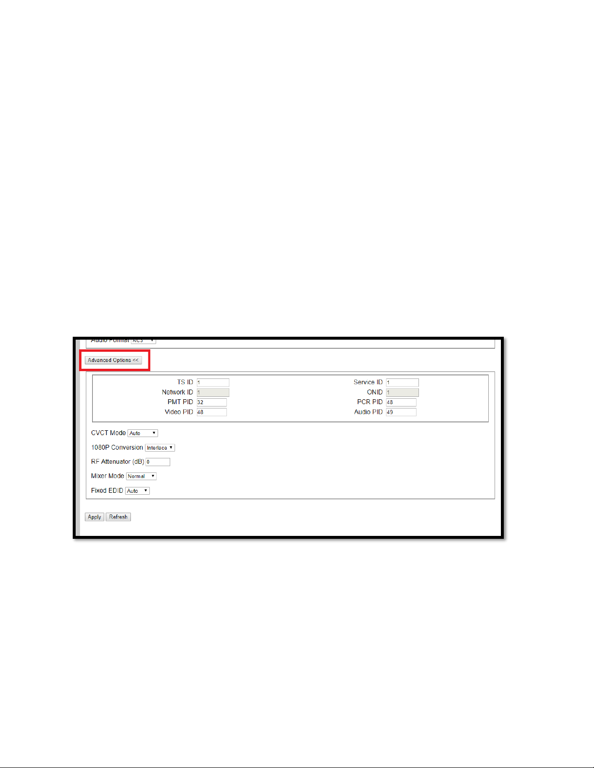
•1080P CONVERSION: If your TV Tuner is older and only supports 1080i video this will
automatically downgrade any 1080P video to 1080i for compatibility. Auto is the default
mode.
•RF ATTENUATION: Built-in digital Attenuator to lower the RF output level. The default setting
is 0 dB, which is full strength. The higher the number, the lower the signal strength.
•MIXER MODE: Used for combability in QAM for older TV’s that still use ATSC 1.0 format. By
default, we are in the max combability mode for all TVs. if you have issues finding the TV or
the channel is found but the screen is black and only audio plays switch to Alternate mode.
•FIXED EDID: Auto is the default mode which allows any HDMI source to feed into the unit to
pass its set resolution. If you have issues where your HDMI source is not being detected by the
unit then set this option to the desired resolution supported by your HDMI source, e.g. 1080,
1080i, 720p. This sends a command to the HDMI source that the only support resolution is the
valve set in this option. This forces the resolution to be stuck in the set value and may not
change.
Click APPLY to lock in changes.
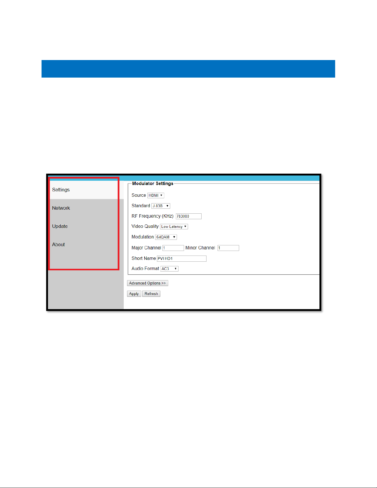
NETWORK TAB: ONLY CHANGE IF YOU ARE INTEGRATING THE UNIT INTO AN EXISTING IP NETWORK.
This menu will allow you to change your device’s IP Address and other network settings. Generally,
you will only need to change these once, when you configure your unit.
•IP ADDRESS: Change only as needed to meet the requirements of your network (Match
the first 2 octets with your network’s settings). If you are using an unmanaged network,
or only direct connection, you can leave it as the default.
•SUBNET MASK: You may need to change this one if your network is heavily managed, or if
you are going through a switch. Otherwise, the default should work fine.

Pro Video Instruments
VeCOAX MicroMod 3 AV + HDMI RF Modulator Manual
9
•GATEWAY: Like your IP address, you will need to configure this to match your current
network settings.
Click APPLY to lock in changes. If the IP Address, etc., is changed, be sure to use the new IP Address to
access the unit’s web interface.
UPDATE TAB: Provides the interface for unit Firmware updates. ONLY USE AS DIRECTED BY PVI
SUPPORT STAFF.
ABOUT TAB: Provides Firmware Version information.

Pro Video Instruments
VeCOAX MicroMod 3 AV + HDMI RF Modulator Manual
10
ON BOARD DISPLAY - QAM (J.83B DIGITAL CABLE)
These are the Defaults and Good
starting point for PLUG N PLAY
setup.
If you have more than one unit
please ensure you change the
FREQUENCY, MAJOR/MINOR, and
SHORT NAME so they don’t
overlap and create issues.
With the above default, the unit
outputs on 783 MHz as channel 1.1.
•SOURCE –Set your Video Source as HDMI or CVBS.
•STANDARD –Set your TV standard depending on
your needs, location, and support format of your TV.
•FREQ –Set your Frequency using our QAM
Frequency chart starting on page 26. TVs will scan for
the Frequency, then store the channel as the
Major/Minor channel number you have set on the
Unit.
•VID QUALITY –Set the Latency Mode of your Video.
•MOD –Modulation Mode you wish to use. QAM64 is
the default and works with 99% of TVs
QAM256 is used in applications that require it such
as with other coax systems that use QAM256 or only
support QAM256 mode
•MAJOR CHANNEL –This is the Major channel
number that will be displayed and stored in the TV’s
Virtual Channel Table (VCT). (For example, for
channel “10.1”, “10” is the Major channel number.)
•MINOR CHANNEL –This is the Major channel
number that will be displayed and stored in the TV’s
Virtual Channel Table (VCT). (For example, for
channel “10.2”, “2” is the Minor channel number.) If
you wish to have many channels with the same
Major number, use the Minor number to
differentiate.
•SHORT NAME –Name of the Channel you wish to
use. 4-6 Characters max depending on TV.
•AUDIO FORMAT –Set your desired Audio Format.
AC3 is the Default Standard for ATSC and QAM
mode.
•ADVANCED –Advanced options for users who
require Specific PIDs or Fixed EDID information.
Please don’t change these unless you understand
your required PIDs or EDID per Cable Provider
instructions or PVI Tech Support request.

Pro Video Instruments
VeCOAX MicroMod 3 AV + HDMI RF Modulator Manual
11
ON BOARD DISPLAY - ATSC
These are the Defaults and Good
starting point for PLUG N PLAY
setup.
If you have more than one unit
please ensure you change the
FREQUENCY, MAJOR/MINOR, and
SHORT NAME so they don’t
overlap and create issues.
With the above default, the unit
outputs on 473 MHz as channel 1.1.
•SOURCE –Set your Video Source as HDMI or CVBS.
•STANDARD –Set your TV standard depending on
your needs, location, and support format of your TV.
•FREQ –Set your Frequency using our ATSC
Frequency chart starting on page 36. TVs will scan for
the Frequency, then store the channel as the
Major/Minor channel number you have set on the
Unit.
•VID QUALITY –Set the Latency Mode of your Video.
•MAJOR CHANNEL –This is the Major channel
number that will be displayed and stored in the TV’s
Virtual Channel Table (VCT). (For example, for
channel “10.1”, “10” is the Major channel number.)
•MINOR CHANNEL –This is the Major channel
number that will be displayed and stored in the TV’s
Virtual Channel Table (VCT). (For example, for
channel “10.2”, “2” is the Minor channel number.) If
you wish to have many channels with the same
Major number, use the Minor number to
differentiate.
•SHORT NAME –Name of the Channel you wish to
use. 4-6 Characters max depending on TV.
•AUDIO FORMAT –Set your desired Audio Format.
AC3 is the Default Standard for ATSC and QAM
mode.
•ADVANCED –Advanced options for users who
require Specific PID’s or Fixed EDID information.
Please don’t change these unless you understand
your required PIDs or EDID per Cable Provider
instructions or PVI Tech Support request.

Pro Video Instruments
VeCOAX MicroMod 3 AV + HDMI RF Modulator Manual
12
ON BOARD DISPLAY - DVB-T GENERIC
These are the Defaults and Good
starting point for PLUG N PLAY
setup.
If you have more than one unit
please ensure you change the
FREQUENCY, LCN, and SHORT
NAME so they don’t overlap and
create issues.
•SOURCE –Set your Video Source as HDMI or CVBS.
•STANDARD –Set your TV standard depending on
your needs, location, and support format of your TV.
•FREQ –Set your Frequency using our DVB-T
Frequency chart starting at page 36. TVs will scan for
the Frequency and the Frequency Channel it relates
to.
•VID QUALITY –Set the Latency Mode of your Video.
•MOD –Modulation Mode you wish to use. QAM64 is
the default and works with 99% of TVs
QAM256 is used in applications that require it such
as with other coax systems that use QAM256 or only
support QAM256 mode
•LCN –Logical channel number can be set here. This
is the channel number that will be stored and
displayed on the TV
•SERVICE NAME –Name of the Channel you wish to
use. 4-6 Characters max depending on TV.
•AUDIO FORMAT –Set your desired Audio Format.
MPEG is the default for DVB-T.
•ADVANCED –Advanced options for users who
require Specific PID’s or Fixed EDID information.
Please don’t change these unless you understand
your required PIDs or EDID per Cable Provider
instructions or PVI Tech Support request.

Pro Video Instruments
VeCOAX MicroMod 3 AV + HDMI RF Modulator Manual
13
ON BOARD DISPLAY - DVB-C
These are the Defaults and Good
starting point for PLUG N PLAY
setup.
If you have more than one unit
please ensure you change the
FREQUENCY, LCN, and SHORT
NAME so they don’t overlap and
create issues.
•SOURCE –Set your Video Source as HDMI or CVBS.
•STANDARD –Set your TV standard depending on
your needs, location, and support format of your TV.
•FREQ –Set your Frequency using our Frequency
chart at www.pvisupport.com. TVs will scan for the
Frequency and the Frequency Channel it relates to.
•SYM. RATE –Set the Symbol Rate appropriate for
your region.
•VID QUALITY –Set the Latency Mode of your Video.
•MOD –Modulation Mode you wish to use. QAM256
is default for DVB-C
•LCN –Logical channel number can be set here. This
is the channel number that will be stored and
displayed on the TV.
•SERVICE NAME –Name of the Channel you wish to
use. 4-6 Characters max depending on TV.
•AUDIO FORMAT –Set your desired Audio Format.
MPEG is the default format for DVB-C.
•ADVANCED –Advanced options for users who
require Specific PID’s or Fixed EDID information.
Please don’t change these unless you understand
your required PID’s or EDID per Cable Provider
instructions or PVI Tech Support request.

Pro Video Instruments
VeCOAX MicroMod 3 AV + HDMI RF Modulator Manual
14
ON BOARD DISPLAY –ISDBT
These are the Defaults and Good
starting point for PLUG N PLAY
setup.
If you have more than one unit
please ensure you change the
FREQUENCY, KEY ID, and SHORT
NAME so they don’t overlap and
create issues.
•SOURCE –Set your Video Source as HDMI or CVBS.
•STANDARD –Set your TV standard depending on
your needs, location, and support format of your
TV.
•FREQ –Set your Frequency using our Frequency
chart at www.pvisupport.com. TVs will scan for the
Frequency and the Frequency Channel it relates to.
•VID QUALITY –Set the Latency Mode of your
Video.
•KEY ID –Set your Key ID channel number.
•SERVICE NAME –Name of the Channel you wish to
use. 4-6 Characters max depending on TV.
•AUDIO FORMAT –Set your desired Audio Format.
AAC is the default standard for ISDBT.
•ADVANCED –Advanced options for users who
require Specific PIDs or Fixed EDID information.
Please don’t change these unless you understand
your required PIDs or EDID per Cable Provider
instructions or PVI Tech Support request.

Pro Video Instruments
VeCOAX MicroMod 3 AV + HDMI RF Modulator Manual
15
ON BOARD DISPLAY –DTMB
These are the Defaults and Good
starting point for PLUG N PLAY
setup.
If you have more than one unit
please ensure you change the
FREQUENCY, LCN, and SERVICE
NAME so they don’t overlap and
create issues.
•SOURCE –Set your Video Source as HDMI or CVBS.
•STANDARD –Set your TV standard depending on
your needs, location, and support format of your TV.
•FREQ –Set your Frequency here. Because of the
wide range that DTMB covers, please search for
these online to determine the Frequencies available
for your region.
•VID QUALITY –Set the Latency Mode of your Video.
•MODE –Modulation mode can be set here
depending on your needs for your region
•LCN –Logical channel number can be set here. This
is the channel number that will be stored and
displayed on the TV
•SERVICE NAME –Name of the Channel you wish to
use. 4-6 Characters max depending on TV.
•AUDIO FORMAT –Set your desired Audio Format.
MPEG is default for DTMB.
•ADVANCED –Advanced options for users who
require Specific PID’s or Fixed EDID information.
Please don’t change these unless you understand
your required PID’s or EDID per Cable Provider
instructions or PVI Tech Support request.

Pro Video Instruments
VeCOAX MicroMod 3 AV + HDMI RF Modulator Manual
16
ON BOARD DISPLAY - ADVANCED MENU
These are the Defaults and Good
starting point for PLUG N PLAY
setup.
Please do not modify these settings
unless instructed or you understand
these settings.
If you require a specific PID set by
your Service provider for Coax STB
injection, then please change as per
their requirements.
Changing these numbers can create
unwanted effects on your channel if
not careful.
•TS ID –Transport ID Number. Used for Identification
of the Mpeg Transport Stream. Default 1
•SERVICE ID –Also known as the Program ID
•CVCT MODE –Allows the changing of the VCT Mode
for TV tuners that have trouble registering the
assigned Major Minor channel and short name. This
option only shows in J.83B standard
•PMT –Program Mapping Table Identification
Number. Metadata of the MPEG transport stream.
Contains the PIDS. Default 32
•VIDEO PID –Identification number for the Mpeg
Video transport stream. Default is 48
•PCR PID –Program Clock rate PID. Required to be
the same number as Video PID to ensure the Video
and Encoder PID’s are synced correctly and Identified
in the Transport stream.
•AUDIO PID –Identification number for the Mpeg
Audio in the transport stream. Default is 49
•1080P CONV–This option will downscale 1080P
video to 1080i automatically when in interlace mode.
If you switch to Auto mode, the unit will not
downscale 1080P video and pass through the
resolution to your tv. Use to support TV tuners that
don’t support 1080P video.
•RF ATTEN –Built-in signal attenuation (reduction).
Reduces signal strength by up to 30 dB.
•MIXER MODE –Compatibility mode for older tuners
that still use DVB ATSC 1.0. If you are having issues
with certain TVs not picking up the channel, please
try the Alternate mode.
•FIXED EDID –Set to force video resolution via HDMI
from source device. HDMI only. By default, the unit
accepts the resolution from the source device (Auto).
•IP SETTINGS - Set the IP Address of Web Interface
and other settings. (See Page 17).
•RESET - Restore unit to factory settings.
Terms:
PID = (Packet Identifier)
CVCT = (Cable Virtual Channel Table)

Pro Video Instruments
VeCOAX MicroMod 3 AV + HDMI RF Modulator Manual
17
ADVANCED MENU –IP SETTINGS
These are the Defaults and Good
starting point for PLUG N PLAY
setup.
Access this menu by going to
Settings -> Advanced -> IP Settings.
•DHCP –Allows IP address of unit to be set
automatically by your network. Disabled by default.
•IP ADDRESS –Set the IP Address for the Web
Interface of the unit. Default is 192.168.0.136.
•NETMASK –Set the Subnet Mask, default is
255.255.255.0.
•GATEWAY –Set the Default Gateway, default is
192.168.0.1.
INSTALLING MULTIPLE UNITS
To install multiple units on the same coax network, make sure to CHANGE the Frequencies,
Major/Minor, and Short Name of each unit BEFORE you connect them to the same coax network, so
there will be no Channel Conflicts. By default, each unit will be set the same. Please Test each unit
directly connected to a Test TV first with a short piece of coax before making it a permanent
installation such as a rack mount to make troubleshooting easier.
If you have other modulators or Digital signals you must find a harmony between the RF levels and
Frequencies that are available such as ATSC (Over the Air Antenna) signal. Check the operating
frequencies of the other signals (i.e. other modulators, OTA channels, etc.), and be sure to set these
units to other valid frequencies.
Depending on your setup we recommend for you to use an active splitter or combiner with more than
6 units, 40+ TVs or using multiple splitters (each splitter will lower the DB level 5-10dbs depending on
the quality) to ensure you get a clear signal to all your TVs no matter the distance. If your system
works without one, then it is not necessary.

Pro Video Instruments
VeCOAX MicroMod 3 AV + HDMI RF Modulator Manual
18
COMBINING SERVICE PROVIDERS SIGNALS OR ATSC WITH YOUR
DEVICE
For Combining ATSC (Over the Air channels) you must find the frequencies that are used by your local
stations. This information can usually be found online by searching for, “(insert your local area) ATSC
frequency chart.” This typically shows all the Frequencies used in your area. Find the ones that are not
used and write those down. Set your device(s) to those unused frequencies. Test using your Test TV.
For combining with Cable Service provider, the same rules apply. You can contact the local service
provider of your basic cable to find the frequencies that they use and find the ones that are available
for you to use. If you wish to inject into a Digital Cable Converter box or STB(set-top box) most of the
time the service provider will include a channel you may broadcast onto or some providers require a
specific PIDs to be set which can be set in the ADVANCED OPTIONS MENU in order for the Set Top box
to be able to read the channel.
AUDIO ENCODING SETTINGS
The unit has three standards of Audio Encoding. Depending on your local and supported format per
TV you can set the following:
•AC3 –2.1 Dolby Digital Audio US/Canada Standard for Broadcasting
•MPEG –MPEG 2 Layer II used in DVB-T EU Standard.
•ACC - Advanced Audio Coding or MPEG-4. Used in some ATSC broadcasts and ISDBT format.
Supported by Most TVs worldwide.

Pro Video Instruments
VeCOAX MicroMod 3 AV + HDMI RF Modulator Manual
19
TROUBLESHOOTING
NO VIDEO
Check for the TEST PATTERN using a test TV, using the unit’s basic setup with default settings.
1. Connect the unit to TV via coax cable. DO NOT connect the HDMI source.
2. Run channel scan on TV (Auto or Cable). After the channel scan, the TV will find the default
channel (1.1).
3. Tune the TV to default channel. TV will show a test pattern ("No Valid Video Input.")
Check for TEST PATTERN using intended channel settings.
1. On the unit’s web interface, set signal standard, Frequency (channel), Major & Minor Channel
numbers to what you wish to use.
2. Confirm that the Frequency is not being used by any other equipment and the Major/Minor
channel number being used is unique.
3. Run channel scan on TV. TV will find the programmed channel.
4. Tune to the programmed channel. TV will show a test pattern ("No Valid Video Input.")
If no TEST PATTERN...
-Check coax cable connection between TV and unit. Test with a different cable if possible.
-Check the TV scan method. Make sure TV is set to scan for the signal type (STANDARD) set on
the unit’s menu. (ATSC corresponds to Over the Air, J83B is QAM Digital cable, etc.) FOR
DEFAULT SETTINGS: set TV to scan for Auto or Cable.
-In rare cases, some TVs may not be able to display the test pattern. Rule this out by connecting
a "dumb" HDMI signal source (e.g. DVD player), then scan for channels on the TV.
-Test with another TV to rule out TV issue if possible.
If TEST PATTERN works but there is NO VIDEO from intended source…
-Check HDMI cable connection between source and unit. Disconnect HDMI source and
reconnect it to establish a new HDMI handshake. Test with a different cable if possible.
-Check resolution settings on the source. Recommended setting is 1080p FIXED or 720p FIXED. If
the source is a computer, set Display to “Extended mode” or “Extend these displays” and set to
1920x1080 or 1280x720.
-In the web interface, go to Advanced Options > Fixed EDID setting, and change from Auto to
match the fixed resolution setting on the source. For instance, if the source is set to 1080p
Fixed, change Fixed EDID to 1080p.
-Test with a different source (e.g. DVD player) if possible
-If possible, test with a different TV with a different make/model.
-Use default settings on the unit. (Reset the unit to default settings, by pressing the Enter and
Escape keys simultaneously, and pressing Enter when prompted to “Recall Default Settings.”)
Table of contents
Other PVI Modulator manuals

PVI
PVI VECOAX MINIMOD 2 PLUS User manual

PVI
PVI VeCOAX ULTRA-HDMI-QAM-IP User manual

PVI
PVI VECOAX ULTRA RF Series User manual

PVI
PVI VeCOAX User manual

PVI
PVI VeCOAX MicroMod-2 User manual

PVI
PVI Vecoax Compact RF Series User manual

PVI
PVI VeCOAX PIXEL User manual

PVI
PVI Vecoax MiniMod 2 User manual

PVI
PVI VECOAX ULTRA RF Series User manual

PVI
PVI Vecoax Compact RF Series User manual
Popular Modulator manuals by other brands

Comtech EF Data
Comtech EF Data Radyne DM240XR Installation and operation manual

Triax
Triax CCS 483 Assembly instruction

Quorum
Quorum GRB-200 Operation, installation, and maintenance manual

Mutable Instruments
Mutable Instruments Tides quick start guide

THORLABS
THORLABS OTKB/M user guide

Audiovox
Audiovox SPS CDC-MC1 owner's manual