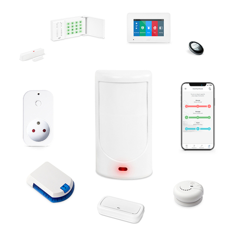
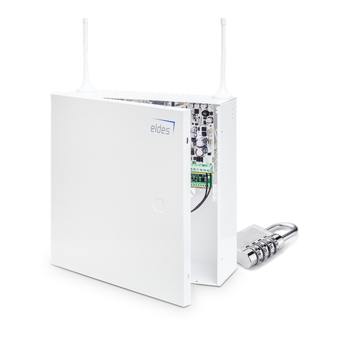
Eldes EPIR2 Instruction sheet

GSM ALARM SYSTEM
EPIR2
CONFIGURATION MANUAL

2
Contents
1. General Information ..............................................................................................................................................................................5
1.1 Protecting your home and property with the EPIR2 alarm system..............................................................................................................................5
1.2 Compatible Device Overview ...................................................................................................................................................................................................5
1.3 Default Parameters & Ways of Parameter Conguration.................................................................................................................................................5
2. Technical Specications .........................................................................................................................................................7
2.1 Electrical & Mechanical Characteristics .................................................................................................................................................................................7
2.2 Main Unit Functionality ..............................................................................................................................................................................................................8
3. Installation ..............................................................................................................................................................................8
4. Conguration & Control .........................................................................................................................................................9
4.1 Primary System Conguration .................................................................................................................................................................................................9
4.2 Ways of System Conguration...................................................................................................................................................................................................9
4.3 Remote System Conguration via GPRS Connection ....................................................................................................................................................10
4.3.1 Establishing Remote Connection Between EPIR2 System and Conguration Server ...........................................................................10
4.3.2 Connecting to ELDES Conguration Server using ELDES Conguration Tool Software .......................................................................11
4.3.3 Ending the Conguration Process ............................................................................................................................................................................11
4.4 Parameter Conguration Set (SMS, EKB3W).......................................................................................................................................................................12
4.4.1 SMS Language .................................................................................................................................................................................................................12
4.4.2 Passwords...........................................................................................................................................................................................................................13
4.4.3 User & Security Guard Phone Numbers...................................................................................................................................................................14
4.4.4 Date & Time .......................................................................................................................................................................................................................15
4.4.5 Zones ...................................................................................................................................................................................................................................16
4.4.6 Wireless PGM Outputs ..................................................................................................................................................................................................21
4.4.7 Alarm & Siren.....................................................................................................................................................................................................................23
4.4.8 Info SMS ..............................................................................................................................................................................................................................25
4.4.9 Alarm Notications .........................................................................................................................................................................................................26
4.4.10 Arm/Disarm Notications ...........................................................................................................................................................................................29
4.4.11 Main Power Supply & Backup Battery Status Notications .............................................................................................................................31
4.4.12 SMS Message Delivery Report....................................................................................................................................................................................32
4.4.13 Remote Listening ............................................................................................................................................................................................................32
4.4.14 System Control from Any Phone Number..............................................................................................................................................................33
4.4.15 Additional Parameters...................................................................................................................................................................................................33
5. ELDES Wireless Devices ....................................................................................................................................................... 36
6. Technical Support ................................................................................................................................................................ 39
6.1 Fault Messages..............................................................................................................................................................................................................................39
6.2 Frequently Asked Questions ...................................................................................................................................................................................................40
6.3 Troubleshooting...........................................................................................................................................................................................................................41
6.4 Restoring Conguration to Default.......................................................................................................................................................................................41
6.5 Upgrading the Firmware using USB Cable .........................................................................................................................................................................41
6.6 Upgrading the Firmware via GPRS Connection (FOTA) ................................................................................................................................................41
7. Monitoring Station............................................................................................................................................................... 42
7.1 Data Messages – Events.............................................................................................................................................................................................................43
7.2 Communication............................................................................................................................................................................................................................45
7.3 GPRS Network ...............................................................................................................................................................................................................................48
7.4 Voice Calls and SMS.....................................................................................................................................................................................................................51

MANUAL ELDES EPIR2 INSTALLATION MANUAL V1.3
3
Conguration Manual v1.3
SAFETY INSTRUCTIONS
for the EPIR22 alarm system
(later referred to as‘the EPIR2’, ‘the system’, ‘the device’‘the unit’ or ‘the detector’)
Please read and follow these safety guidelines to safeguard yourself and others:
• DO NOT use the system where it can interfere with other devices - such as medical devices
• The alarm system radio transceiver operates in the GSM850, GSM900, GSM1800 and GSM1900 bands
• DO NOT use the system in hazardous environments
• DO NOT expose the system to high humidity, chemical environments or mechanical impact
• DO NOT attempt to repair the system yourself - any repairs must be carried out by fully qualied personnel only
The EPIR2 comes with its own power supply unit so you can plug it in straight away. The unit is not meant for outdoor
use, i.e. you should use it inside a building and the power supply must be plugged into a standard Euro 2-pin socket or
UK 3-pin socket (depending on the version you have bought). The main circuit should be protected by short circuit or
over-current protection.
Please use the power supply unit which comes with your EPIR2, as it meets the EN 60950-1 standard. Any additional de-
vice you connect to the system, such as a computer, must also be powered by an EN 60950-1 approved supply.
Any additional devices linked to the system EPIR2 (computer, sensors, relays etc.) must be approved by LST EN 60950-1
standard.
Disconnect the mains power before installing. Never install or carry out maintenance during stormy weather. The electric socket
that powers the system must be easily accessible. In case of power cut, the system is powered by a back-up battery.
WARNING: Only use the approved back-up battery with the system to avoid re or explosion. Take care when connect-
ing positive and negative battery terminals.
To switch the system o, unplug the external electric power supply and disconnect the battery by rst removing the front
cover of the device. A blown fuse cannot be replaced by the user. The replacement fuse has to be of the kind indicated by
the manufacturer (fuse F1 type – C1S 2.5A).
If you use a computer to select your ideal settings, it must be earthed.
The WEEE (Waste Electrical and Electronic Equipment) symbol on this product (see left) means it must not be disposed
of in household waste. To prevent possible harm to human health and/or the environment, you must dispose of this
product in an approved and environmentally safe recycling facility. For further information contact your system sup-
plier, or your local waste authority.

4
Limited Liability
The buyer agrees that the system will reduce the risk of re, theft, burglary or other danger but that it does not guarantee against the
occurrence of such events.
ELDES UAB will not take any responsibility for the loss of personal eects, property or revenue whilst using the system. The liability of
ELDES UAB is limited to the value of the system purchased.
ELDES UAB is not aliated with any mobile/wireless/cellular provider and is therefore not responsible for the quality of such services.
Manufacturer Warranty
The system carries a 24-month manufacturer warranty from ELDES UAB.
The warranty begins the day the system is purchased by the user and the receipt must be retained as proof of purchase date. The
warranty remains valid only if the system is used as intended, following all guidelines outlined in this manual and in accordance with
the operating conditions specied.
The warranty is void if the system has been exposed to mechanical impact, chemicals, high humidity, uids, corrosive and hazardous
environments or force majeure factors.
Package Content
EPIR2 alarm system .................................................. 1
Power supply ................................................................1
User manual ..................................................................1
MiniUSB cable ..............................................................1
Back-up battery ...........................................................1
Screws .............................................................................1
5,6kΩ resistor.................................................................1
Not included: You will need to supply your own SIM card – we recommend you get a contract SIM, not Pay As You Go.
Dear Customer,
Thank you for choosing to purchase the EPIR2 alarm system to protect your property.Your thoughtful decision will ensure reliable
protection for many years as all ELDES products are manufactured to meet the highest standards.
We are condent that you will be completely satised with your product. However, in the unlikely event that you do experience a
problem, please contact the dealer from whom you made your purchase.
Copyright ©“ELDES UAB”, 2012. All rights reserved.
It is forbidden to copy and distribute information in this document without advance written authorisation from ELDES UAB. We reserve
the right to update or modify this document and/ or related products without warning. The EPIR2 GSM Alarm System complies with the
essential requirements and relevant provisions of Directive 1999/5/EC. The declaration of conformity may be viewed at www.eldes.lt

MANUAL ELDES EPIR2 INSTALLATION MANUAL V1.3
5
1. General Information
1.1 Protecting your home and property with the EPIR2 alarm system
Where and how to use the alarm system
The EPIR2 is a convenient, easy to use, remote control security system for houses, cottages, country homes, garages and other buildings.
It uses an internal SIM card (not supplied by ELDES) and an infra red sensor, and communicates with your mobile phone so you can:
• Protectyourpropertywhileyouareawayfromhome
• Listentowhatishappeninginyourpropertyfollowingasecurityalert
• Switchthesystemonorofromanywhereintheworldatnocost
• ReceiveSMS/textmessagesupdatingyouonthesystemstatus
• Includeuptoveuserstoreceivesystemstatusmessagesand/orsecurityalerts
1.2 Compatible Device Overview
Wireless Devices
Device Description Max. Connectable Devices
EW1* Wireless 2 zone and 2 PGM output expansion module 16*
EWP1* Wireless PIR motion detector 16*
EWD1* Wireless magnetic door contact 16*
EWK1* Wireless key-fob with 4 buttons 5*
EWS1* Wireless indoor siren 16*
EWS2* Wireless outdoor siren 16*
EKB3W* Wireless LED keyboard 4*
* - A mixed combination of wireless devices is supported. The combination can consist of up to 16 wireless devices in total.
1.3 Default Parameters & Ways of Parameter Conguration
Main Parameters
Parameter Default Value
Congurable by:
SMS EKB3W Conguration
Tool
SMS Language Depends on rmware version according to user‘s location
SMS Password 0000
User Password 1 1111
User Password 2... 10 N/A
Admin Password 1470
User 1... 10 Phone Number N/A
Security Guard Phone Number N/A
Allow Only Preset Users Enabled
Date & Time N/A
Zones
Parameter Default Value
Congurable by:
SMS EKB3W Conguration
Tool
Zone Alarm Text Z1 - Alarm Zone1, Z2 - Alarm Zone2, Z3 - Alarm Zone3 etc.
Entry Delay 15 seconds
On-board Z1 Zone Type Follow
Exit Delay 15 seconds
EKB3W Zone Type Instant
Wireless Zone Type Depends on the connected wireless device
Virtual Zone Type Follow
On-board Z1 Zone Status Enabled

6
Zones
Parameter Default Value
Congurable by:
SMS EKB3W Conguration
Tool
EKB3W Zone Status Disabled
Wireless Zone Status Enabled
Virtual Zone Status Disabled
Stay Mode for a Specied Zone Disabled
Tamper Name Box Tamper; Tamper 2, Tamper 3 etc.
Wireless PGM Outputs
Parameter Default Value
Congurable by:
SMS EKB3W Conguration
Tool
Wireless PGM Output Name C1 – Controll1, C2 – Controll2, C3 – Controll3 etc.
Wireless PGM Output Status Enabled
Wireless PGM Output Type Depends on the connected wireless device
Alarm & Siren
Parameter Default Value
Congurable by:
SMS EKB3W Conguration
Tool
Alarm Duration 1 minute
Bell Squawk Disabled
Activate Siren if Wireless Device is Lost Disabled
EWS2 LED Enabled
Periodic Info SMS, SMS Delivery Report, Alarm & Arm/Disarm Notications
Parameter Default Value
Congurable by:
SMS EKB3W Conguration
Tool
Periodic Info SMS Period – 1; Time - 11
SMS Delivery Report Enabled
Call in Case of Alarm Enabled
Send SMS in Case of Alarm Enabled
Send Alarm SMS to User 1... 5 Enabled
Send Alarm SMS to All Users Simultaneously Disabled
Send Alarm SMS to Security Guard Enabled
Send Arm/Disarm SMS to User 1... 5 Enabled
Send Arm/Disarm SMS to
All Users Simultaneously
Disabled
Send Arm/Disarm SMS to Security Guard Enabled
Main Power & Battery Status Notications
Parameter Default Value
Congurable by:
SMS EKB3W Conguration
Tool
Send SMS in Case of Main Power Loss/Restore Enabled
Send SMS in Case of Battery Trouble Enabled
Monitoring Station
Parameter Default Value
Congurable by:
SMS EKB3W Conguration
Tool
MS Mode Disabled
Data Messages All Enabled
Account (Alarm System ID) 9999
Monitoring Station Phone Number 1... 3 (Voice
Calls/SMS)
N/A
Call Attempts 3
Server IP Address (GPRS) 0.0.0.0
DNS1 Server IP Address (GPRS) N/A

MANUAL ELDES EPIR2 INSTALLATION MANUAL V1.3
7
Monitoring Station
Parameter Default Value
Congurable by:
SMS EKB3W Conguration
Tool
DNS2 Server IP Address (GPRS) N/A
Protocol (GPRS) TCP
Server Port (GPRS) 20000
Local Port (GPRS) N/A
APN (GPRS) N/A
User (GPRS) N/A
Password (GPRS) N/A
Prole Prole1
Primary Connection GPRS Network
Backup Connection 1... 2 N/A
GPRS Attempts 3
Delay after last communication attempt 600 seconds
Device ID (Monitoring Station ID) 0000
Test Period (GPRS) 180 seconds
Additional Parameters
Parameter Default Value
Congurable by:
SMS EKB3W Conguration
Tool
LED Indication for Movement Detection Disabled
PIR Detector (Motion Detector) Level 40
Microphone Gain 12
Speaker Level 85
Keyboard Back-light Timeout 10 seconds
2. Technical Specications
2.1 Electrical & Mechanical Characteristics
Supply voltage 11-15V 500mA max
Back-up battery voltage, capacity 8.4V; 250mAh
Back-up battery type Ni-Mh
GSM modem frequency 850/900/1800/1900 Mhz
Dimensions 104x60x33mm
Operating temperature range -10…+40 °C
Humidity 0-90% RH @ 0... +40 °C (non-condensing)
Back-up battery operating time up to 24 hours*
Detection angle 90°
Maximum motion detection range 10 metres
Wireless transmitter-receiver frequency 868 Mhz
Wireless communication range up to 30m in premises; up to 150m in open areas
Maximum number of wireless devices 16
Communications SMS, Voice Calls, GPRS Network
Supported protocols Ademco Contact ID, EGR100, Kronos, Cortex SMS
BELL+: siren output commuted values Current - 150mA max.; voltage - 15V (EPIR2 on external power supply) / 7V (EPIR2
on backup battery)
* - with Smart Security disabled; with wireless transmitter-receiver module disabled

8
2.2 Main Unit Functionality
3. Installation
The system should be installed indoors, in stationary environment. Choose the installation location where unauthorized
access is most probable:
To avoid false alarms, do not install the system in the following locations:
• locatinglenstowardsdirectsunshine,e.g.facingwindows;
• neardeviceswithhightemperatureuctuations,e.g.replaceorheatingboiler;
• areasofincreaseddustorairowtrac;
• metalorshieldedwallwhichmaycauseGSMconnection(andwirelessifany)interference.
Fig. No. 4
BACK SIDE INSIDE VIEW
1
8
4
2
7
8
9
12
BELL- / COM
BELL+
Z2
13
3
5
16 6 315
10
11
14
SIM
GSM
BATTERY
1. EPIR2 holder for xing on the wall
2. Lens for movement detector and LED
3. Power supply socket to connect to mains electricity
4. Power supply transformer
5. Power supply connection lead
6. Reset button to restore default parameters
7. Holder to x the unit in place
8. Mini-USB connector to allow programming via your PC
9. Holder for SIM card
10. GSM module
11. Back-up battery in case of mains power supply failure
12. Motion detector to sense possible intruders
13. TAMPER button to alert you if anyone interferes with the
unit
14. Microphone to allow you to listen in to an incident using
your mobile phone
15. Wired zone & output for siren or electrical appliance con-
nection
16. Built-in GSM antenna
Connector Description
BELL- / COM Siren output negative terminal / output
terminal / common return terminal
Z2 Security zone terminal
BELL+ Siren output positive terminal
Fig. No. 1
Fig. No. 2 Fig. No. 3

MANUAL ELDES EPIR2 INSTALLATION MANUAL V1.3
9
4. Conguration & Control
ATTENTION! In this user manual the underscore symbol ”_” represents one space character. Every underscore symbol must be
replaced by a single space character. There must be no space or other unnecesary characters at the beginning and at the end of
the message. XXXX – 4-digit SMS password (the default SMS password is 0000 – four zeros).
The system conguration and control can be performed by sending SMS messages to EPIR2 phone number, using EKB3W wireless
keyboard, via USB connection locally or GPRS connection remotely using ELDES Conguration Tool software, which is recommended
for quick and more convenient system conguration.
4.1 Primary System Conguration
1. Set the language. See chapter 4.4.1 SMS Language for more details.
2. Change the default SMS password. See chapter 4.4.2 Passwords for more details.
3. Set the phone number for User 1. See chapter 4.4.3 User Phone Numbers for more details.
After completing these steps the system is ready for further conguration.
If you fail to receive an SMS reply from the system, please, check the SMS centre phone number.
4.2 Ways of System Conguration
In order to congure and control the system using SMS message, send the text command to EPIR2 system phone
number from one of the preset user phone numbers. The structure of SMS message consists of 4 digit SMS password
(the default SMS password is 0000 – four zeros), the parameter and value. For some parameters the value does not
apply, i.e. STATUS.
The system conguration and control by EKB3W wireless keyboard is performed by activating the Conguration Mode
using the administrator password (the default administrator password is 1470) and entering a valid conguration com-
mand using the number keys (0... 9) and [#] key for conrmation. The indication of each pressed key is provided by zone
red LEDs when entering a conguration command. The structure of standard conguration command is a combination
of digits. EKB3W conguration command and valid parameter value range are indicated in brackets.
NOTE: Due to battery power saving reasons the keyboard LEDs and back-light are turned o in 10 seconds (by default) after the last
key-stroke. To invoke EKB3W, press any key once. However, this key-stroke will be considered as the rst character of the command.
SMS centre phone number is stored in a SIM card by the GSM operator, therefore if the SIM card has
already been successfully used to send SMS messages from a mobile phone, then it is not necessary
to change the SMS centre number.
This command activates and deactivates the Conguration Mode.
Set SMS Centre
Phone Number
Conguration
Mode
SMS text:
0000_SMS_+4411111111111
Example: 0000_SMS_+446545417732
Enter administrator password:
[*aaaa#]
Value: aaaa – 4-digit adiministrator password.
SMS
EKB3W
SMS
EKB3W

10
EKB3 indications which are relevant during Conguration Mode are described in the table below.
Indication Description
Red LED ARMED ashing Conguration mode activated successfully.
Yellow LED SYSTEM ashing Valid parameter is entered and waiting for value.
1 Long Beep Non-existing command or parameter value entered.
3 Short Beeps Command entered successfully.
NOTE: The system can be congured using one keyboard at a time only. Other connected keyboards become inactive in Con-
guration Mode.
Software ELDES Conguration Tool is intended to work directly with EPIR2 alarm system, which can be connected to the
computer via USB port or via GPRS connection remotely. This software simplies system conguration process by allow-
ing to use a personal computer in the process. Before starting to use ELDES Conguration Tool, please, read user guide
available in the software’s HELP section. ELDES Conguration Tool is freeware and can be downloaded from ELDES website
at: www.eldes.lt
4.3 Remote System Conguration via GPRS Connection
Before conguring EPIR2 remotely via GPRS connection, make sure that:
• SIMcardisinsertedintoEPIR2device.
• MobileinternetserviceisenabledontheSIMcard.
• PowersupplyisconnectedtoEPIR2.
• DefaultSMSpasswordischangedtoanew4-digitpassword;
• AtleastUser1 phone number is set up.
4.3.1 Establishing Remote Connection Between EPIR2 System and Conguration Server
CONFIGU
RATION
TOOL
In order to activate a remote GPRS connection between EPIR2 system and ELDES congu-
ration server, please, send the following SMS message from user phone number.
Upon the successful SMS message delivery, the system establishes a connection session for
20 minutes. An SMS reply, containing device IMEI number and conrming a successful con-
nection establishment, is sent shortly.
In case it is necessary to establish a connection between EPIR2 system and a third-party con-
guration server, send the following SMS message.
SMS text:
XXXX_stcong
Example: 1111_stcong
SMS text:
XXXX_stcong:IPaddress:Port
Value: Ipaddress – public IP address of third-party conguration server; Port –
port number of third-party conguration server, HostName - public host-name of
third-party conguration server.
Example: 1111_stcong:62.80.115.102:4522
Initiate the
Connection to
ELDES Server
Initiate the
Connection to
Third-Party Server
SMS
SMS or XXXX_stcong:HostName:Port
NOTE: Public IP address (host-name) and port number are necessary when connecting to a third-party-server for the rst time
only. When connecting to the server next time, XXXX_stcong is enough as the IP address (host-name) and port number are
saved in the device memory after the rst successful connection.

MANUAL ELDES EPIR2 INSTALLATION MANUAL V1.3
11
4.3.2 Connecting to ELDES Conguration
Server using ELDES Conguration Tool Software
4.3.2.1 Run ELDES Conguration Tool software.
4.3.2.2 Press Remote Conguration button.
4.3.2.3 In the next window, select Connect to Remote Serv-
er (recommended) and press Next button.
4.3.2.4 Enter the received IMEI number in Device IMEI entry.
4.3.2.5 Press Continue button.
4.3.2.6 Upon the successfully established connection, the sys-
tem prompts for an administrator password.
4.3.2.7 By entering a valid administrator password, the sys-
tem grants access to full conguration remotely.
4.3.2.8 Remote Conguration Management window dis-
plays all performed conguration actions.
4.3.3 Ending the Conguration Process
After the system conguration is complete, use one of the following methods to end the con-
guration process:
• Press Disconnect button and close ELDES Conguration Tool software;
• Wait for the system to reply with an SMS message conrming the end of the session;
• Shut down the connection with the server at any time by sending an SMS message.
Shut down the
Connection with
the Server
SMS text:
XXXX_endcong
Example: 1111_endcong
SMS

12
4.4 Parameter Conguration Set (SMS, EKB3W)
4.4.1 SMS Language
This command sets the language for SMS message replies. The user is allowed to switch
between all available languages at any time.
Set SMS Language
SMS
SMS text:
LL
Value: LL – system language, possible values – LT, RU, EN, EE, LV, IS, GR, DE, FI,
FR, SP, SK, CZ
Example: EN
EKB3W
Enter parameter 35 and language index number:
[350#] - Lithuanian
[351#] - Russian
[352#] - English
[353#] - Estonian
[354#] - Latvian
[355#] - Icelandic
[356#] - Greek
[357#] - German
[358#] - Finnish
[359#] - French
[3510#] - Spansih
[3511#] - Slovak
[3512#] - Czech
NOTE: In order to change the SMS language in a congured system (after changing the SMS password), please, use ELDES Con-
guration Tool software.

MANUAL ELDES EPIR2 INSTALLATION MANUAL V1.3
13
4.4.2 Passwords
The 4-digit SMS password intended for system conguration and control by SMS messages.
Default value is 0000 (four zeros) which is NECESSARY to change.
4-digit password intended for arming and disarming the alarm system using a keyboard. Up
to 10 dierent user passwords can be set. Newly added user password is automatically as-
signed to the same partition as the keyboard. Default User Password 1 value is 1111 and it is
pre-assigned to partition 0.
This command replaces an existing user password with a new one.
Set SMS Password
Set User Password
Replace User
Password
SMS
SMS text:
YYYY_PSW_XXXX
Value: YYYY – old 4-digit password, range - [0000... 9999]; XXXX – new 4-digit
password, range - [0000... 9999]
Example: 0000_PSW_1111
EKB3W
Enter parameter 14 and SMS password:
[14xxxx#]
Value: xxxx – 4-digit SMS password, range - [0000... 9999]
SMS
N/A
EKB3W
Enter parameter 15, user password number & new user password:
[15yyxxxx#]
Value: yy – user password number, range – [01... 10]; xxxx – new user password,
range – [0000... 9999]
SMS
N/A
EKB3W
Enter parameter 63, old user password & new user password:
[63yyyyxxxx#]
Value: yyyy – old user password, range – [0000... 9999]; xxxx – new user pass-
word, range – [0000... 9999].

14
4.4.3 User & Security Guard Phone Numbers
This command erases a particular user password. It is possible to delete the password assi-
gned to the same partition as the keyboard only.
The 4-digit administrator password providing access to system conguration. It is recommen-
ded to change the default admin password which is 1470.
The system supports up to 10 authorized phone number entries allowing system congu-
ration and control by SMS. User 1 phone number is mandatory while other phone number
entries are not necessary. The supported phone number formats are the following:
• International (with plus) – The phone numbers must be entered starting with plus and
an international country code in the following format: +[international code][area code]
[local number], example for UK: +4417091111111.
• International (with 00) – The phone numbers must be entered starting with 00 and an
international country code in the following format: 00[international code][area code][lo-
cal number], example for UK: 004417091111111.
• Local – The phone numbers must be entered be entered starting with an area code in the
following format: [area code][local number], example for UK: 017091111111.
Delete User
Password
Set Administrator
Password
Set User Phone
Number
SMS
N/A
EKB3W
Enter parameter 65 & user password:
[65xxxx#]
Value: xxxx – 4-digit user password, range - [0000... 9999]
SMS
N/A
EKB3W
Enter parameter 16 & administrator password:
[16aaaa#]
Value: aaaa– 4-digit administrator password, range - [0000... 9999]
SMS
SMS text:
XXXX_NR1:YYYYYYYYYYYYYYY _NR2:VVVVVVVVVVVVVVV_ NR3:ZZZZZZZZZZZZZZZ_
NR4:UUUUUUUUUUUUUUU_NR5:NNNNNNNNNNNNNNN_NR10:GGGGGGGGGGGGGGG
Value: YYYYYYYYYYYYYYY – up to 15 digits user phone number
Example: 1111_NR1:+4411111111111
EKB3W
Enter parameter 17, user number & phone number:
[17xxyyyyyyyyyyyyyyy#]
Value: xx – user number, range – [01... 10]; yyyyyyyyyyyyyyy – up to 15 digits
user phone number

MANUAL ELDES EPIR2 INSTALLATION MANUAL V1.3
15
This phone number is intended for receiving Arm/Disarm SMS messages and SMS text mes-
sages in case of alarm. This number is NOT allowed to perform system arming/ disarming or
make any congurations. The supported phone number formats are the following:
• International (with plus) – The phone numbers must be entered starting with plus
and an international country code in the following format: +[international code][area
code] [local number], example for UK: +4417091111111.
• International (with 00) –The phone numbers must be entered starting with 00 and an
international country code in the following format: 00[international code][area code]
[local number], example for UK: 004417091111111.
• Local – The phone numbers must be entered be entered starting with an area code in
the following format: [area code][local number], example for UK: 017091111111.
This feature allows to check the list of added user phone numbers to the system.
In order to receive SMS messages containing correct date and time, please, set date and time
of the system.
Set Security Guard
Phone Number
List User Phone
Numbers
Set Date & Time
SMS
N/A
EKB3W
Enter parameter 55, user number & phone number:
[55yyyyyyyyyyyyyyy#]
Value: yyyyyyyyyyyyyyy – up to 15 digits Security Guard phone number
SMS
SMS text:
XXXX_HELPNR
Example: 1111_HELPNR
SMS
SMS text:
XXXX_YYYY.MM.DD_HH:MM
Value: YYYY– year; MM – month, range – [01... 12]; DD – day, range - [01... 31];
HH – hours, range – [00... 23], MM – minutes, range – [00... 59].
Example: 1111_2011.12.15_13:45
EKB3W
Enter parameter 66, date & time:
[66yyyymmddhhmm#]
Value: yyyy– year; mm – month, range – [01... 12]; dd – day, range - [01... 31];
hh – hours, range – [00... 23], mm – minutes, range – [00... 59].
4.4.4 Date & Time
NOTE: When the alarm system is connected to a monitoring station the date and time are set automatically. The system re-
trieves this information from the monitoring station.

16
Each secured zone has an alarm text which is sent by SMS message in case of alarm. Default
values: Z1 - Alarm Zone1, Z2 - Alarm Zone2 etc. Alarm text can be edited by SMS or ELDES
Conguration Tool software only. The length of zone alarm text for each zone can be up to 24
characters including space characters.
This command provides the list of violated zones.
This command provides the list of violated tampers.
Set Zone Alarm Text
View Violated Zones
View Violated
Tampers
SMS
SMS text:
XXXX_Z1:NewAlarmText;Z2:NewAlarmText;Z3:NewAlarmText;
Z4:NewAlarmText;Z5:NewAlarmText;Z6:NewAlarmText;Zn:NewAlarmText
Example: 1111_Z1:SensorTriggered
EKB3W
N/A
SMS
Please, refer to chapter 4.4.8 Info SMS.
EKB3W
For violated zone Z1 - Z12 indication, please, check the zone LED indicators on
EKB3W device. For violated high-numbered zone Z13 - Z34 indication, please,
refer to chapter 6.1 Fault messages.
SMS
The system noties by SMS containing violated tamper number (unless tam-
per name is erased using ELDES Conguration Tool software).
EKB3W
[CODE2]
For violated tamper 13 - 34 indication, please, refer to chapter 6.1 Fault mes-
sages
4.4.5 Zones
NOTE: Colons, semi-colon characters, parameter names and/or values are not allowed in zone alarm texts, eg. PSW, STATUS,
ON, OFF etc.
NOTE: Due to security reasons it is recommended to restore the violated zone before arming the alarm system. In order to arm
the alarm system despite violated zone presence, you can bypass it.

MANUAL ELDES EPIR2 INSTALLATION MANUAL V1.3
17
Entry delay is a period of time intended to disarm the alarm system after the user enters the
secured area (after Delay zone is violated). The alarm will be caused in case the system is not
disarmed during this period of time. Default value is 15 seconds and Delay zone is Z1.
Exit delay is a period of time intended for user to leave the secured area. The system begins
the countdown after the ar ming process initiation. Default value is 15 seconds.
This command disables a particular zone. By default, on-board zone and wireless zones
(except EKB3W zones) are enabled.
Set Entry Delay
Set Exit Delay
Disable Zone
SMS
SMS text:
XXXX_ENTRYDELAY:Zn,YY
Value: Zn - zone number, range - [Z1... Z34]; YY - entry delay duration in seconds,
range - [0... 65535];
Example: 1111_ENTRYDELAY:25,14
EKB3W
Enter parameter 54, zone number & entry delay duration:
[54xxyyyyy#]
Value: xx - zone number; yyyyy – entry delay duration in seconds, range - [0...
65535]
SMS
SMS text:
XXXX_EXITDELAY:YY
Value: YY - exit delay duration in seconds, range - [0... 600]
Example: 1111_EXITDELAY:25
EKB3W
Enter parameter 72 & exit delay duration:
[72xxx#]
Value: xxx– exit delay duration in seconds, range – [0... 600]
SMS
SMS text:
XXXX_Zn:OFF
Value: Zn – zone number, range – [Z1... Z34]
Example: 1111_Z4:OFF
EKB3W
Enter parameter 52 & parameter status value:
[52xx0#]
Value: xx – zone number, range – [01... 34]
NOTE: EKB3W mini-buzzer provides short beeps during entry delay countdown only if the Delay zone violated within the
countdown is a built-in EKB3W zone.

18
This command enables a particular zone. By default, all keyboard zones and virtual zones are
disabled. Virtual zones can be enabled using ELDES Conguration Tool only.
Zone bypassing allows to temporally disable a particular violated zone before arming the
system.
This command activates a particular bypassed zone.
Alternative way: Bypassed zones become active again after arming & disarming the alarm
system.
Enable Zone
Bypass Zone
Activate a
Bypassed Zone
SMS
SMS text:
XXXX_Zn:ON
Value: Zn – zone number, range – [Z1... Z34]
Example: 1111_Z3:ON
EKB3W
Enter parameter 52 & parameter status value:
[52xx1#]
Value: xx – zone number, range – [01... 34]
SMS
N/A
EKB3W
Enter zone number & user password:
[BYPSxxyyyy#]
Value: xx – zone number, range – [01... 34]; yyyy – 4-digit user password
SMS
N/A
EKB3W
Enter zone number & user password:
[BYPSxxyyyy#]
Value: xx – bypassed zone number, range – [01... 34]; yyyy – 4-digit user pass-
word
ATTENTION: Zone bypassing and activation is performed without Conguration Mode being enabled.

MANUAL ELDES EPIR2 INSTALLATION MANUAL V1.3
19
Each zone can be set to operate under one of these types:
• Interior Follower – The zone can be violated during exit and entry delay without causing an
alarm. If the zone is violated before the entry delay has begun, it will cause an instant alarm.
The zone is used where violating a zone during exit/entry delay is unavoidable. Typically, this
zone is used for indoor protection devices, such as motion detectors, installed close to the
exit/entry doors.
• Instant – The alarm is instantly caused if this zone is violated when the system is armed or du-
ring entry delay. This zone type is usually used for doors, windows or other zones, and shock
detectors.
• 24-Hour – When the system is either armed or disarmed, the zone will cause instant alarm
if violated. Normally, this type of zone is used for securing the areas that require constant
supervisory.
• Delay –This zone type can be violated during exit and entry delay without causing an alarm. If
the zone is violated when the system is armed, it will initiate entry delay countdown intended
for the user to disarm the system. If the zone is left violated after the exit delay expires, it will
cause an instant alarm. If the zone is not violated and restored during exit delay, the system
will be armed in Stay mode. Typically, this zone type is used for door contacts installed at
designated exit/entry doors.
• Fire – If this zone type is violated when the system is either armed or disarmed, the alarm will
be instantly caused and the siren/bell will emit pulsating sound. Typically, this zone type is
used for ame and smoke detectors.
• Panic/Silent – This zone operates the same as 24-Hour zone type, but the system will not
activate the siren/bell and keypad buzzer if violated. Normally, this zone type used for panic
alarm buttons.
Stay mode enables the users to arm and disarm the alarm system while staying inside the se-
cured premises. The system goes into Stay mode in case the Delay zone is not violated during
the Exit Delay countdown (the user does not leave the secured area) and the zones which are
congured as Stay will not be secured. Stay mode is not activated if the user leaves the secu-
red premises during Exit Delay countdown or if none of the zones are congured to operate
under Stay mode. By default, this feature is disabled for all zones.
Set Zone Type
Enable Stay Mode
Attribute for a
Specied Zone
SMS
N/A
EKB3W
Enter parameter 53, zone number & zone type index:
53xx1#] - Interior Follow
[53xx2#] - Instant
[53xx3#] - 24-Hour
[53xx4#] - Delay
[53xx5#] - Fire
[53xx6#] - Panic/Silent
Value: xx – zone number, range – [01... 34]
SMS
N/A
EKB3W
Enter parameter 56, zone number & parameter status value:
56xx1#
Value: xx – zone number, range – [01... 34].

20
Stay mode enables the users to arm and disarm the alarm system while staying inside the se-
cured premises. The system goes into Stay mode in case the Delay zone is not violated during
the Exit Delay countdown (the user does not leave the secured area) and the zones which are
congured as Stay will not be secured. Stay mode is not activated if the user leaves the secu-
red premises during Exit Delay countdown or if none of the zones are congured to operate
under Stay mode. By default, this feature is disabled for all zones.
This feature provides the list of zone and wireless PGM output statuses (enabled/disabled,
turned on/o). In addition, the SMS message contains zone alarm texts, wireless PGM output
names and alarm system status (armed/disarmed).
Disable Stay Mode
Attribute for a
Specied Zone
View Zone &
Wireless PGM
Output Status
Activate Stay
Mode Manually
SMS
N/A
EKB3W
Enter parameter 56, zone number & parameter status value:
[56xx0#]
Value: xx – zone number, range – [01... 34]
SMS
SMS text:
XXXX_STATUS
Example: 1111_STATUS
EKB3W
N/A
Press [STAY] key & enter user password:
[STAYxxxx]
Value: xxxx – 4-digit user password
ATTENTION: To arm the system in Stay mode, there must be at least 1 zone with Stay mode attribute enabled.
EKB3W
Other manuals for EPIR2
2
Table of contents
Other Eldes Security System manuals
Eldes
Eldes EPIR2 User manual
Eldes
Eldes EPIR User manual

Eldes
Eldes ESIM264 User manual

Eldes
Eldes ESIM264 User manual

Eldes
Eldes ESIM264 User manual

Eldes
Eldes EWS4 User manual

Eldes
Eldes EPIR2 Installation instructions
Eldes
Eldes ESIM364 User manual

Eldes
Eldes ESIM364 User manual

Eldes
Eldes ESIM264 User manual
