AquaSAFE™quick reference guide
for residential re safety systems
This guide is meant for reference only and does not intend to
cover all applications or specic construction features. Always
follow the requirements of NFPA 13D, sprinkler listings and
local codes and ordinances. If in doubt about any requirements,
contact the Authority Having Jurisdiction (AHJ).
Jobsite review
Always review the design prints and walk the job to verify before
starting the installation.
Sprinkler locations
Mark sprinkler mounting locations—indicate sprinkler node
(e.g., H13) from the design print.
Sprinkler mounting details
Correct placement of ProPEX® re sprinkler adapters depend
on the type of sprinkler heads and the thickness of the ceiling
material being used. Refer to the design prints for proper
mounting dimensions. Always eld verify with escutcheons
or cover plates to ensure proper t (measure and/or test with
ceiling material).
Tubing supports
Only use Uponor tube talons (F7050750 or F7051000) or
other supports intended for plastic tubing. Refer to Table 1
for tubing supports.
AquaSAFE™ systems
Use ProPEX engineered polymer (EP) or lead-free (LF) brass
tees or EP multiport tees between sprinkler adapters to connect
cold-water plumbing xtures.
Pendent sprinklers
Typically mount 1" from the face of the ceiling. Refer to the
sprinkler manufacturer’s guideline installation bulletin(s) for
specic sprinkler listings and mounting requirements.
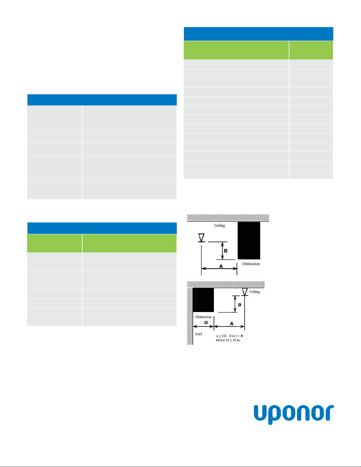
Sidewall sprinklers
Typically mount 4" to 6" from the ceiling; may be located up to
12" from the ceiling to avoid obstructions. Design prints and
hydraulic calculations must reect mounting positions 6" to 12".
Sprinkler deectors
Always mount parallel to the plane of the ceiling.
Sloped ceilings
Refer to the sprinkler manufacturer’s guideline installation
bulletin(s) for specic ow, pressure, coverage and listing
information when installing sprinklers in sloped ceiling
applications. At least one sprinkler must be installed within 3'
vertically from the ridgeline.
Heat sources
Maintain 12" spacing between Uponor AquaPEX® tubing and
heating ducts or recessed lighting xtures. Refer to Table 4 on
the back of this page for minimum sprinkler spacing from heating
ducts, diffusers and other heat sources.
Attic spaces (insulation)
Ensure adequate insulation when running tubing in attic
spaces. Refer to NFPA 13D, Annex A or the Uponor AquaSAFE
Attic Insulation Guidelines on uponorpro.com for additional
information.
Field modications
Submit marked-up design prints to Uponor Design Services
at design.services@uponor.com. Some changes may require
additional hydraulic calculations.
Flow test verication
Uponor recommends submission of a Flow Test Verication
Form for every installation. Refer to the AquaSAFE Flow Test
Instruction Sheet available on uponorpro.com. Be sure to use
the proper test orice.
Warning sign
Afx adjacent to the main shutoff valve.
Sprinkler spacing
Refer to Table 2 on the back of this page for sprinkler spacing
requirements. Always refer to the NFPA 13D Standard, the
sprinkler manufacturer’s guideline installation bulletin(s) or
contact Uponor Design Services at design.services@uponor.com
for special requirements.
Tubing support table
Horizontal runs,
unsupported
Horizontal runs,
supported Vertical runs
Every 32" Every 72"
Every 4' to 5';
at each floor with a
mid-story guide
When installed in exposed (unfinished) areas, metal hangers designed
for use with non-metallic tubing are required every 24".
Table 1: Tubing support table